
4300 - Tuner NAD - Kostenlose Bedienungsanleitung
Finden Sie kostenlos die Bedienungsanleitung des Geräts 4300 NAD als PDF.


| Produkttyp | Stereo Tuner (Monitor-Serie) |
| Marke | NAD |
| Modell | 4300 |
| Frequenzbereiche | FM (UKW): 87,5–108 MHz AM (MW): 530–1710 kHz (10 kHz Schritt) / 531–1602 kHz (9 kHz Schritt) |
| Senderspeicher | 16 (8 FM, 8 AM) mit Speichererhaltung >2 Wochen ohne Netz |
| Antennenanschlüsse | AM: integrierte Ferritstabantenne und Klemmen für Außenantenne FM: 75-Ohm-Koaxialbuchse (mit Balun-Adapter für 300-Ohm-Bandleitung) |
| Ausgänge | Cinch (links/rechts) mit regelbarem Ausgangspegel |
| Besondere Funktionen | IF-Narrow-Filter (schmalbandig), FM-Rauschunterdrückung (FM NR) mit Ausschaltmöglichkeit, Mono-Umschaltung |
| Anzeigen | Digitalfrequenzanzeige, Signalstärkeanzeige (5 Balken), FM-Stereo-LED, IF-Narrow-LED, Mittenabstimmungsanzeige (FM) |
| Abstimmung | Digital mit Drehknopf, Schrittweite FM 0,05 MHz, AM 10 kHz (USA) / 9 kHz (Europa) |
| Stromversorgung | Wechselspannung (über Netzkabel), ungeschaltete Steckdose auf der Rückseite |
Häufig gestellte Fragen - 4300 NAD
Benutzerfragen zu 4300 NAD
0 Frage zu diesem Gerät. Beantworten Sie die, die Sie kennen, oder stellen Sie Ihre eigene.
Eine neue Frage zu diesem Gerät stellen
Laden Sie die Anleitung für Ihr Tuner kostenlos im PDF-Format! Finden Sie Ihr Handbuch 4300 - NAD und nehmen Sie Ihr elektronisches Gerät wieder in die Hand. Auf dieser Seite sind alle Dokumente veröffentlicht, die für die Verwendung Ihres Geräts notwendig sind. 4300 von der Marke NAD.
BEDIENUNGSANLEITUNG 4300 NAD

4300 STEREO TUNER
MONITOR SERIES
Spares
Dept
INSTRUCTIONS FOR INSTALLATION AND OPERATION
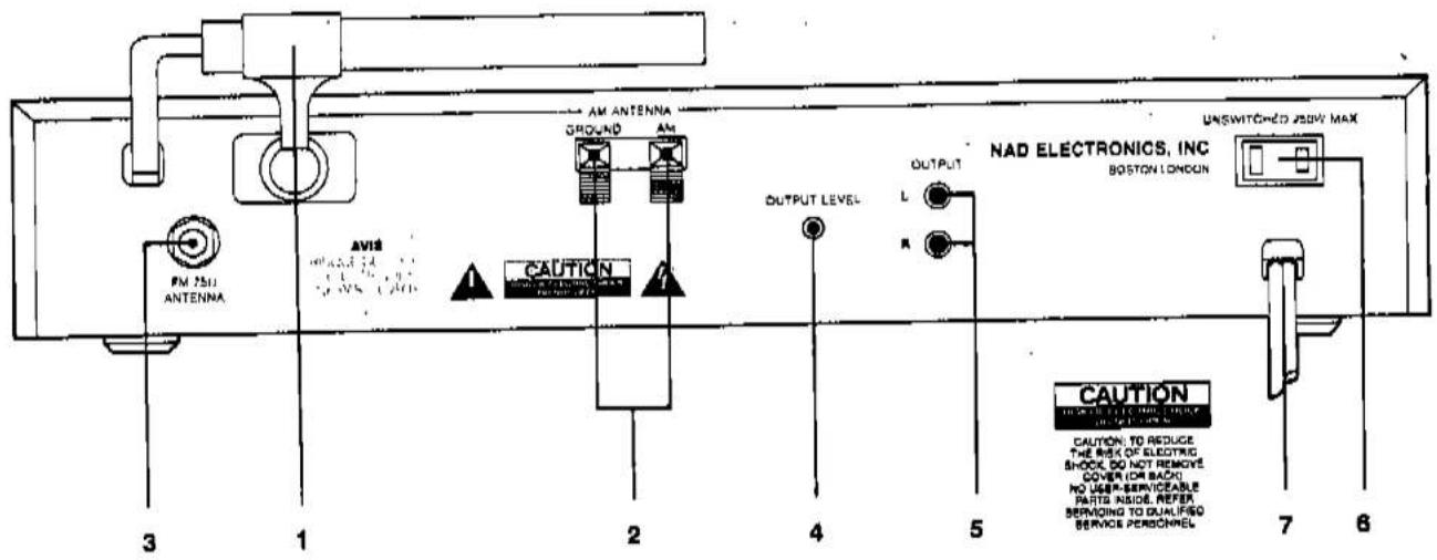
REAR PANEL
- AM Rod Antenna.
- AM Antenna Terminals.
- FM Antenna Input.
-
Output Level Control.
-
Output Jacks.
- AC Convenience Outlet (not in U.K. model).
- AC Line Cord
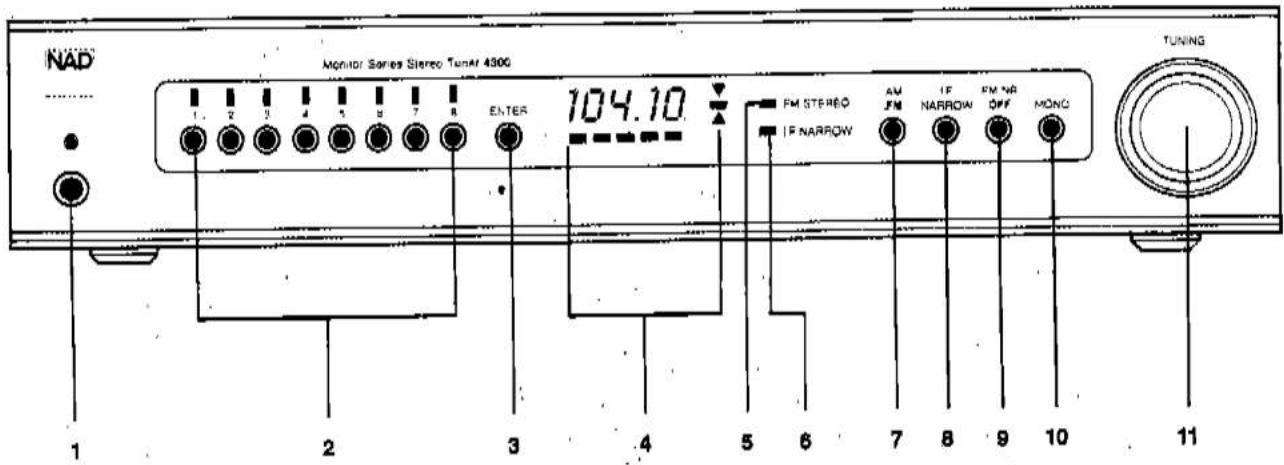
FRONT PANEL
- Power.
- AM/FM.
- Station Pre-sets.
- IF Narrow.
- Memory Enter. B. FM NR Off.
- Tuning Display. 10. Mono.
- FM Stereo Indicator. 11. Tuning.
- IF Narrow Indicator.
REAR PANEL CONNECTIONS
1. AM ROD ANTENNA
The ferrite rod antenna provides effective reception of local medium-wavelength AM radio stations. The rod is mounted on a pivot. For best reception, swing it away from the metal chassis of the receiver.
2. AM ANTENNA TERMINALS
Since the tuner is equipped with a ferrite rod antenna, no external antenna will be needed for satisfactory reception of most local broadcasting stations. But if you wish to improve reception of distant AM stations, attach a long-wire outdoor antenna to the AM terminal. As its name implies, a "long-wire" antenna is a simple, straight wire whose length may be anything from a few feet up to about 100 feet (30 meters), mounted parallel to the earth and as high as is convenient.
In some cases the effectiveness of a long-wire antenna will be improved by connecting a second wire from the Ground (G) terminal to a true earth-ground, i.e. a copper-plated rod driven several feet into the earth. A substitute electrical ground may also prove effective: a cold-water pipe, a steam radiator, or the third hole of a modern electrical wall socket.
3. FM ANTENNA INPUT
The FM antenna input socket is designed to accept a 75-ohm "co-axial" cable. This type of shielded cable is employed with community cable systems, apartment building master antenna systems, and most roof-mounted antennas.
If you want to connect an antenna with a 300-ohm twin-lead wire, use a "balun" (an adapter containing a 300-to-75-ohm transformer).
An antenna must be connected to the tuner for effective reception of stereo FM broadcasts. A ribbon-wire "folded dipole" antenna and a balun adapter are included to get you started. When you stretch out the ribbon-wire antenna you will note that it is in the form of a T. The "crossbar" portion of the T should be stretched out horizontally and tacked in place (on a wall, on the back of a cabinet, or on the floor). The "vertical" section of the T goes to the tuner's antenna input. Connect its two wires to the screw terminals on the balun adapter; then plug the balun into the tuner's FM input socket.
In view of the exceptional sensitivity of this tuner, you may find that the ribbon-wire dipole antenna is all you need for reception of strong local stations. But this simple antenna is not very efficient at rejecting "multipath" and other forms of FM Interference, and it cannot easily be rotated to optimize its pickup pattern for best reception of stations in different directions. Therefore, in most cases you should use a better antenna. The recommended options, in order of increasing cost, are as follows:
(1) A basic "rabbit-ears" indoor TV antenna without auxiliary coils or tuning switches. Electrically, such an antenna is just another dipole (similar to the ribbon-wire antenna). But since its tuned elements are made of solid metal, it can easily be rotated. Stretch out each of its two arms to a length of 30 inches (75 cm), and orient them horizontally or at a shallow angle (less than 45 degrees upward). The ribbon wire emerging from the antenna's base should be connected to the balun adapter's screw terminals In place of the simple ribbon-wire antenna. Now, for each station in turn, after you tune the station you can rotate the antenna for best reception.
(2) A more elaborate rabbit-ears indoor TV antenna with a tuning switch. This type of antenna does NOT have greater sensitivity than the simpler rabbit-ears unit, so if your problem is that the signals you want to receive are weak (as shown on the signal-strength meter), then an outdoor antenna is the only effective solution. But in cities and in large buildings where signals are strong but are contaminated by reflected "multipath" interference, the tuning switch on an elaborate indoor antenna may improve reception by reducing the interference.
(3) An electrically tuned Indoor antenna. Again, such antennas usually do not provide any advantage over the simplest type of "rabbit-ears" unit for receiving weak signals. But where strong signals are contaminated with interference, the antenna's aiming and tuning controls can reject the interference and yield cleaner reception.
(4) An outdoor antenna. Even the finest indoor antenna, no matter how elaborate, cannot fully exploit the capabilities of a good FM tuner. For the lowest noise, minimum distortion, and largest choice of well-received broadcasts, an outdoor antenna is the best complement to a fine tuner.
A roof-mounted antenna has three fundamental advantages. First, its large size yields better sensitivity (pulling in a stronger signal from the desired station) and a narrower directional pattern for more effective rejection of multipath reflections arriving from other directions. Second, its location on a roof or tall mast places it above many sources of interference—passing cars and buses, other buildings, etc. Third, the strength of received FM signals is directly proportional to the height of any antenna above the ground.
If you already have an outdoor television antenna, using a splitter to extract FM signals from it may produce excellent results. However, many TV antennas are deliberately designed to be relatively weak at FM frequencies in order to minimize potential interference with TV signals at nearby frequencies (Channel 6 in the U.S.). You may be able to use a splitter to extract FM signals from an apartment building's master TV antenna system, but usually this yields poor results because many master antenna systems have "traps" to stop FM signals.
The best choice is a directional FM-only antenna, mounted as high above ground as is practical, and separated by at least two meters (7 feet) from other antennas, vertically and horizontally. If desired stations are located in different directions (more than 80 degrees apart), the antenna should be mounted on a rotor for aiming. Brand names of good FM antennas in the U.S. include Jerrold, Finco, Wineguard, Antennacraft, and Archer (Radio Shack).
Use shielded lead-in cable rather than plain "twin-lead" wire, both to minimize interference and to preserve strong signals during years of weathering. The cable may be either 75-ohm coaxial or a shielded 300-ohm type. Disconnect any indoor antenna from the tuner before connecting the outdoor antenna.
If you install an outdoor antenna yourself, observe these important CAUTIONS:
- Do not mount the antenna close to electric power lines. Plan the installation so that the antenna mast cannot
The lightning flash with arrowhead, within an equilateral
triangle, is intended to alert the user of the presence of uninsulated "dangerous voltage" within the product's enclosure; that may be of sufficient magnitude to constitute a risk of electric shock to persons
The exclamation point within an equilateral triangle is intended to alert the user of the presence of important operating and maintenance (servicing) instructions in the literature accompanying the appliance.
accidentally touch power lines, either while you are installing it or later.
- Include a lightning arrestor in the installation, to protect both yourself and the tuner circuit from potential danger during electrical storms.
4. OUTPUT LEVEL CONTROL
This control varies the volume level of the tuner's output. You may leave it set at maximum, or you may use this control to adjust the tuner's output so as to minimize any change in volume level when you switch your amplifier from PHONO to TUNER.
5. OUTPUT JACKS
Connect a stereo patch cord from the Left and Right output jacks to the corresponding Tuner Input jacks on your amplifier.
6. AC CONVENIENCE OUTLET (not in U.K. model)
The AC power line cord of another stereo component may be plugged Into this accessory outlet. It is an "un-switched" outlet, unaffected by the Power button.
7. AC LINE CORD
Plug the AC line cord into a Switched outlet on your amplifier, or into any AC wall outlet that provides the correct power-line voltage.
FRONT PANEL CONTROLS
1. POWER
Depress this button to switch on the power. The frequency display will illuminate when the power is on. To switch the power off, press the button again and release it.
In many installations it may be more convenient to leave the tuner's POWER switch permanently engaged, letting the tuner be turned on and off by a "switched" convenience outlet on your amplifier.
If you prefer, you may plug the tuner's AC line cord into an Unswitched outlet or directly into a wall socket, and leave it permanently turned on. The tuner's power consumption is very low, so the cost of leaving it always on would be only a few dollars per year; and the useful life of the tuner would not be shortened by leaving it on.
2. STATION PRE-SETS
You can store the frequencies of sixteen favorite stations (eight FM and eight AM) in these pre-sets, using the ENTER button. Then, to tune those stations from day to day, just press the appropriate pre-set button.
The pre-sets preserve their frequency assignments when the power is switched off, or when the AC line cord is unplugged, for a period of at least two weeks. Thus you can re-arrange your stereo system, or move the equipment from room to room, without losing the pre-set frequencies. But if you leave the power off for a month or more, you may have to re-program the tuning pre-sets.
3. MEMORY ENTER
This button engages the Memory Enter mode. Use this mode to enter the frequencies of your favorite stations in the sixteen pre-sets (eight pre-sets on the FM band and another group of eight pre-sets on AM). The procedure is as follows.
(1) Decide which station you want to assign to each pre-set. On each band you may arrange the stations in any order that you find convenient to use or easy to remember: alphabetical (1=WABC, 2=WCBS, 3=WNYC...), numerical (1=BBC1, 2=BBC2...), or in order of increasing frequency (1=89.7, 2=90.9, 3=95.3, etc). If you are not certain of the frequencies of the stations, check the station/frequency directory in a local newspaper or broadcasting guide.
(2) Select the FM or AM band, as appropriate. Using the Tuning control, manually tune to the first station on your list. Check the signal-strength display (AM) or center-tune indicator (FM) to be sure that you have tuned precisely to the center of the station's broadcast channel. Press the ENTER button, then press Pre-set #1 to store the first station in the tuner's memory. (NOTE: After you press ENTER, you will have approximately ten seconds to store a station in one of the pre-sets. After that interval, the ENTER mode will automatically de-activate.)
(3) Tune to the second station on your list. Press the ENTER button and, within ten seconds, press Pre-set #2 to store the second station.
(4) Tune to the third station on your list, press ENTER, and press Pre-set #3 to store the station. Continue in this manner with any other stations that you want to store in the remaining pre-sets. Then switch to the other tuning band (FM or AM) and repeat the process for the second set of five pre-sets.
Incidentally, If you make a mistake or change your mind, it is not necessary to re-program all eight pre-sets in sequence. You can re-program any pre-set simply by tuning to the desired frequency, pressing ENTER, and pressing the pre-set that you want to re-program.
After you finish programming the pre-sets, you may wish
to post your list of stations and associated pre-set numbers nearby for reference.
CAUTION: In day-to-day operation, be careful not to press the ENTER button by accident. Doing so will activate the ENTER mode, and if you then press any of the pre-set buttons you will unintentionally re-program that pre-set. You would then have to manually re-tune to the station you wanted, and re-ENTER it into the pre-set.
If you press ENTER accidentally, you may wait ten seconds for the ENTER mode to disengage. Or you can immediately force the tuner out of the ENTER mode, in either of two ways: switch to the other tuning band (e.g., from FM to AM and back), or turn the Tuning knob to change the frequency.
4. TUNING DISPLAY
This display is in three parts: frequency, signal strength, and tuning.
FREQUENCY. The numerical display shows the tuned frequency.
SIGNAL STRENGTH. The signal strength meter is a series of five bars. The number of illuminated bars increases with the strength of the received signal. If only one or two bars illuminate, the signal is too weak for noise-free reception in stereop, but reception may be satisfactory in mono. Strong signals are indicated by four or five illuminated bars. The greatest benefit of FMX noise-reduction occurs at signal strengths from two to four bars.
TUNING. The center-tuning indicator (FM only) consists of an illuminated rectangular bar and two triangular pointers. The pointers glow when the tuning is within an FM station's channel but not at the center of that channel. The orientation of the illuminated pointer shows whether the tuning frequency should be increased or decreased. If the indicator points upward, rotate the Tuning knob clockwise to increase the frequency. If the indicator points down, turn the knob counter-clockwise to decrease the frequency. When the broadcast is accurately centered, the triangular pointers fade out and only the middle bar is illuminated.
On the AM band, tune for maximum signal strength.
6. FM STEREO INDICATOR
This LED illuminates when a stereo FM broadcast is being received and decoded by the tuner's multiplex decoder circuit. Note that if the MONO button is engaged, all broadcasts will be received in mono.
6. IF NARROW INDICATOR
This LED illuminates when IF NARROW button has been pushed in.
7. AM/FM
This button switches between the two tuning bands: FM or medium-wave AM. The digital tuning display shows the tuned frequency in MHz (for FM) or kHz (for AM).
The tuning circuit has a "last station selected" memory. When you switch between tuning bands, the circuit automatically re-tunes the last station that you were tuned to when you previously used that band.
8. IF NARROW
This button should normally be OUT. The OUT position provides a moderately wide bandwidth for the I.F. circuit, in order to obtain maximum stereo separation and minimum distortion.
When this button is pressed, it provides a narrow I.F. bandwidth with sharper selectivity. Use the Narrow setting when you need to separate stations that are very closely spaced in frequency—especially to improve the reception of a weak signal that is adjacent to the frequency of a strong signal.
9. FM NR OFF
The tuner contains an FM Noise Reduction circuit that automatically reduces noise in weak FM stereo signals by reducing the stereo separation. As the received signal becomes weaker and the stereo subcarrier becomes noisler, the circuit automatically reduces the contribution of the stereo subcarrier to the final sound, obtaining the best practical compromise between queting and subjective image breadth. Even with maximum noise reduction, the circuit maintains enough channel separation to produce a stereo image that is appreciably wider and more spacious than mono.
For normal operation of the circuit, leave the button OUT. The FM noise-reduction circuit operates only on those weak stereo FM signals that would be noisy without it. It does not affect the reception of strong signals.
If you want to turn off the noise-reduction and restore full stereo separation, press the FM NR OFF button. You may not hear an obvious difference when this button is pressed, since most broadcast signals are strong enough to disengage the circuit automatically.
10. MONO
The MONO button disables the stereo FM circuits in the tuner.
Normally the tuner receives monophonic FM transmissions in mono and automatically switches on its multiplex decoding circuits when a stereo FM broadcast is received (as shown by the FM STEREO indicator). But when a very weak FM stereo signal is received, it may be excessively noisy because of the multiplex encoding technique used for stereo broadcasting. In that case, depress the MONO button to lock the tuner in the mono mode, in order to obtain consistently quieter and cleaner sound.
Remember to disengage the MONO button when you re-tune to a stronger signal. As long as the MONO button is engaged, no broadcasts can be received in stereo.
11. TUNING
Rotation of the tuning knob generates digital pulses that increase or decrease the tuned frequency in small steps. The minimum tuning increment is 0.05 MHz for FM. For the AM band the tuning step is 10 kHz in North America (9 kHz in Europe and elsewhere).
To increase the tuned frequency, turn the knob to the right (clockwise). To decrease the tuned frequency, turn the knob to the left (counter-clockwise).


- STEREO TUNER
- MONITOR SERIES
- REAR PANEL
- FRONT PANEL
- REAR PANEL CONNECTIONS
- AM ROD ANTENNA
- AM ANTENNA TERMINALS
- FM ANTENNA INPUT
- OUTPUT LEVEL CONTROL
- OUTPUT JACKS
- AC CONVENIENCE OUTLET (not in U.K. model)
- AC LINE CORD
- FRONT PANEL CONTROLS
- POWER
- STATION PRE-SETS
- MEMORY ENTER
- TUNING DISPLAY
- FM STEREO INDICATOR
- IF NARROW INDICATOR
- AM/FM
- IF NARROW
- FM NR OFF
- MONO
- TUNING
Marke : NAD
Modell : 4300
Kategorie : Tuner