
PDUMV20HVNETLX - Rack-Steckdosenleiste Tripp Lite - Kostenlose Bedienungsanleitung
Finden Sie kostenlos die Bedienungsanleitung des Geräts PDUMV20HVNETLX Tripp Lite als PDF.

| Produkttyp | Intelligente Rack-Steckdosenleiste (geschaltete PDU) |
| Marke und Modell | Tripp Lite PDUMV20HVNETLX |
| Stromversorgung | 208-230 V AC, 16 A (einphasig) |
| Formfaktor | Vertikal 0U für Rackmontage |
| Steckdosen | IEC C13 und C19 (Anzahl variiert je nach Modell) |
| Überwachungsfunktionen | Fernüberwachung über Netzwerkschnittstelle, lokales digitales Amperemeter |
| Steuerungsfunktionen | Individuelle Fernsteuerung der Steckdosen (Schalten) |
| Netzwerkkonnektivität | Ethernet RJ45-Anschluss, integrierte Web-Management-Karte (WEBCARDLX) |
| Anzeige | Digitales Amperemeter mit Anzeige der Gesamtlast (und pro Bank bei einigen Modellen) |
| Sicherheit | Schutzschalter pro Lastbank (ausgewählte Modelle) |
| Montage | Werkzeuglose Montage mit Knöpfen (SmartRack® und kompatible Racks) oder mit mitgelieferten Halterungen |
| Mitgeliefertes Zubehör | Montagehalterungen, Kabelrückhalteschlaufen, Plug-Lock C14/C20-Einsätze, Eingangssteckeradapter (je nach Modell), RJ45-DB9-Kabel |
| Umgebung | Nur für den Innenbereich, Umgebungstemperatur 0 bis 50 °C, ohne Überspannungsschutz |
| Garantie | 2 Jahre |
Häufig gestellte Fragen - PDUMV20HVNETLX Tripp Lite
Benutzerfragen zu PDUMV20HVNETLX Tripp Lite
0 Frage zu diesem Gerät. Beantworten Sie die, die Sie kennen, oder stellen Sie Ihre eigene.
Eine neue Frage zu diesem Gerät stellen
Laden Sie die Anleitung für Ihr Rack-Steckdosenleiste kostenlos im PDF-Format! Finden Sie Ihr Handbuch PDUMV20HVNETLX - Tripp Lite und nehmen Sie Ihr elektronisches Gerät wieder in die Hand. Auf dieser Seite sind alle Dokumente veröffentlicht, die für die Verwendung Ihres Geräts notwendig sind. PDUMV20HVNETLX von der Marke Tripp Lite.
BEDIENUNGSANLEITUNG PDUMV20HVNETLX Tripp Lite
Owner's Manual
Monitored Rack PDU Switched Rack PDU
0U (Vertical) Format
PDUMNV20HVLX
(208/230V 16 Amp Monitored Model)
Series Number: AGPD7897
PDUMV20HVNET2LX
(208/230V 16 Amp
Switched Model)
Series Number: AGPD7897
PDUMNV30HVLX
(208/240V 24 Amp Monitored Model)
Series Number: AGPD7898
PDUMV30HVNETLX
(208/230V 24 Amp Switched Model)
Series Number: AGPD7898
PDUMNV32HV2LX
(200-240V 32A Monitored Model)
Series Number: AG-00CA
Important Safety Instructions 2
Monitored Rack PDU Features 2
Switched Rack PDU Features 3
Installation 3
Features 8
Configuration and Operation 11
Service 11
Warranty and Product Registration 12
Español 13
Français 25
Русский 37
Deutsch 49
PROTECT YOUR INVESTMENT!
Register your product for quicker service and ultimate peace of mind. You could also win an ISOBAR6ULTRA surge protector—a \$100 value!
www.tripplite.com/warranty


Manufacturing Excellence.
1111 W. 35th Street, Chicago, IL 60609 USA • www.tripplite.com/support
Copyright © 2019 Tripp Lite. All rights reserved.
Important Safety Instructions
SAVE THESE INSTRUCTIONS
This manual contains instructions and warnings that should be followed during the installation, operation, and storage of this product. Failure to heed these instructions and warnings will void the product warranty.

PRECAUCION Este aparato no se destina para utilizarse por personas (incluyendo niños), cuyas capacidades físicas, sensoriales o mentales sean diferentes o estén reducidas, o carezcan de experiencia o conocimiento, a menos que dichas personas reciban una supervisión o capacitación para el funcionamiento del aparato por una persona responsable de su seguridad.
Los ninos deben de supervisarse para asegurar que no empleen el aparato como juguete.
Nunca utilize el aparato si el cable y la clavija están dañados; si no funciona correctamente o si se ha caido o dañado, llévelo a un centro de servicio autorizado para que lo examinen y lo reparen.
Si el cordon de alimentación es dañado, éste debe sustituirse por el fabricante, por su agente de servicio autorizado o por personal calificado con el fin de evitar un peligro.
- The PDU provides the convenience of multiple outlets, but DOES NOT provide surge or line noise protection for connected equipment.
- The PDU is designed for indoor use only, in a controlled environment, away from excess moisture, temperature extremes, conductive contaminants, dust or direct sunlight.
- Keep indoor ambient temperature between 0^ and 50^ (32°F and 122°F).
- The PDU must be installed by a qualified technician only.
- Do not attempt to mount the PDU to an insecure or unstable surface.
• Install in accordance with National Electrical Code standards. Be sure to use the proper overcurrent protection for the installation, in accordance with the plug/equipment rating. - Connect the PDU to an outlet that is in accordance with your local building codes and that is adequately protected against excess currents, short circuits and earth faults.
- The electrical outlets supplying power to the equipment should be installed near the equipment and easily accessible.
- Do not connect the PDU to an ungrounded outlet or to extension cords or adapters that eliminate the connection to ground.
- Be sure to provide a local disconnect device on any models that are permanently installed without a plug that is easily accessible.
- Never attempt to install electrical equipment during a thunderstorm.
- Individual equipment connected to the PDU should not draw more current than the individual PDU's outlet's rating.
- The total load connected to the PDU must not exceed the maximum load rating for the PDU.
- Do not attempt to modify the PDU, input plugs or power cables.
- Do not drill into or attempt to open any part of the PDU housing. There are no user-serviceable parts inside.
- Do not attempt to use the PDU if any part of it becomes damaged.
- Use of this equipment in life support applications where failure of this equipment can reasonably be expected to cause the failure of the life support equipment or to significantly affect its safety or effectiveness is not recommended.
Monitored Rack PDU Features
• Network interface enables remote power monitoring and event notification.
• Digital amp meter for on-site load monitoring.
- Optional EnviroSense2 modules (E2MT, E2MTDO, E2MTDI, E2MTHDI) allow for a variety of environmental monitoring and control options.
- Toolless button-mount installation in Tripp Lite SmartRack® and many third-party enclosures.
Switched Rack PDU Features
• Network interface enables remote power monitoring and individual outlet control.
- Individually controllable outlets allow remote rebooting of locked-up network devices.
• Digital amp meter for on-site load monitoring.
- Optional EnviroSense2 modules (E2MT, E2MTDO, E2MTDI, E2MTHDI) allow for a variety of environmental monitoring and control options.
- Toolless button-mount installation in Tripp Lite SmartRack and many third-party enclosures.
Installation
Mounting the PDU
Note: The illustrations may differ somewhat from your PDU model. Regardless of configuration, the user must determine the fitness of hardware and procedures before mounting. The PDU and included hardware are designed for common rack and rack enclosure types and may not be appropriate for all applications. Exact mounting configurations may vary. Screws for attaching the mounting brackets and cord retention shelf to the PDU are included. Use only the screws supplied by the manufacturer, or their exact equivalent (#6-32, 14 " flat head).
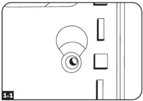
If installing the PDU in a rack that has button-mount slots, you only need to perform step 1-1. If your rack enclosure does not have button-mount slots, proceed to step 1-2.
1-1 To install the PDU in a rack equipped with button-mount slots, insert the mounting buttons on the rear of the PDU into the button-mount slots on the rack and slide the PDU down until the mounting buttons engage the narrow section of the button-mount slots.
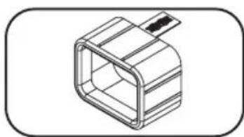
Note: To install the PDU with its outlets facing the rear of the rack, use the included PDUMVROTATEBRKT accessory. This V-shaped bracket provides a mounting button on one leg of the V and a button-mount slot on the other, effectively repositioning the mounting buttons. See Features section for image.
natural_image
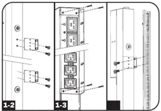
Pure technical diagram of a device casing with no text, numbers, or symbols1-2 Attach the mounting brackets to the PDU.
1-3 (Optional) Attach the cord retention bracket(s) to the PDU.
1-4 Attach the PDU to a vertical rail in your rack or rack enclosure. Use the included mounting hardware to attach the mounting brackets to the rail.
Installation
Connecting the PDU
2-1
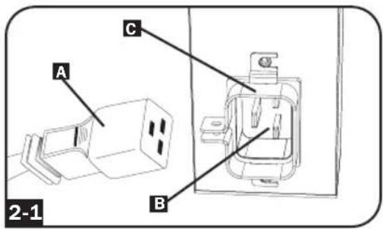
(Models with IEC power inlet or 3-pole IEC 309 plug only) Select models have a detachable power cord. Attach the included power cord to the PDU by inserting the IEC connector A of the power cord into the IEC power inlet B located near the end of the PDU. Use the included bracket C to secure the power cord connection.
Note: Optionally, a user-supplied power cord can be attached to the PDU by connecting it to the IEC inlet. Do not attempt to attach a user-supplied power cord unless it is certified to be compatible with the input power source that will be used by the PDU.
2-2
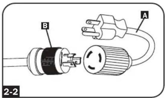
(Optional - models with input plug adapter only) Select models include an input plug adapter that converts the twist-lock input plug to a straight-blade input plug. Attach the input plug adapter A to the input plug B if you wish to plug the PDU into a compatible straight-blade outlet.
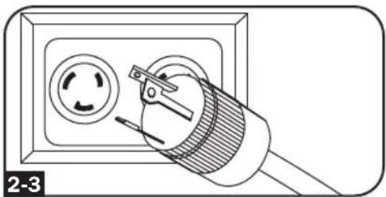
2-3
Connect the input plug to a compatible AC power outlet. If the PDU does not have a circuit breaker, it should be provided with a branch-rated over-current protection device that matches the rated amperage of the PDU.
Note: The AC power source should not share a circuit with a heavy electrical load.
2-4
(Option 1 - select models only) If you attached the cord retention bracket(s), tie each equipment power cord to the retention bracket. Attach each cord to the retention shelf by looping the cord and securing it with one of the included cable ties A. Make sure that each cord can be unplugged from the PDU without removing the cable tie.
(Option 2) Use the included C14 and C20 plug-lock inserts to secure plugs to receptacles. Attach the insert onto the plug, making sure that the pull tabs B remain outside the plug and that the fit is secure. To unplug equipment properly, use the pull tabs to remove the plug and insert from the receptacle.
natural_image
Line drawing of an electrical outlet with a cable and circular socket (no text or symbols)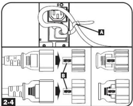
Installation

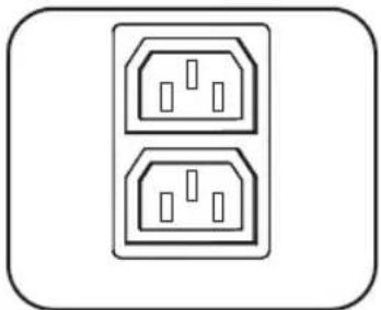
Connect your equipment's input plugs A to the outlets B of the PDU. The LED C near each outlet (Switched Models Only) illuminates when the outlet is ready to distribute live AC power. The digital load meter D displays the total connected equipment load in amps. (Select models provide additional load data. See the Features section for more information.)
Note: In order to minimize interference among connected devices, connect each device to the nearest PDU outlet and coil excess power cord length.
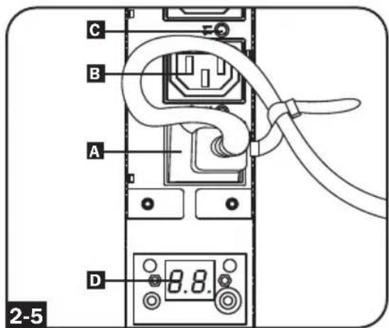
(Configuration may vary by model.)
Networking the PDU
Note: The MAC address of the PDU (a 12-digit string in this format: 00 06 67 XX XX XX) is printed on a label attached to the PDU enclosure.
If your network's DHCP server will assign a dynamic IP address to the PDU automatically, go to Step 3-1. If you will assign a static IP address to the PDU manually, go to Step 4-1. If you are uncertain which method to use, contact your network administrator for assistance before continuing the installation process.
Dynamic IP Address Assignment

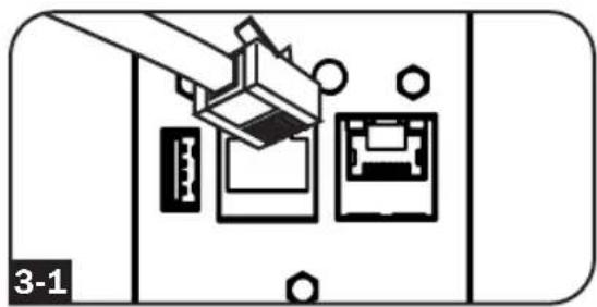
Connect Web Management Card to Network: Connect a standard Ethernet patch cable to your network using the RJ45 Ethernet port on your Web Management Card.
Note: This port does not support PoE (Power over Ethernet) applications.
The card will attempt to obtain an IP address via DHCP. This may take as long as several minutes, depending on your network environment.
natural_image
Diagram of a device with three ports and a cable, no text or symbols present
Determine IP Address: To identify the IP address assigned to the Web Management Card, contact your network administrator and provide the MAC address of the Web Management Card. You can also determine the IP address locally at the card.
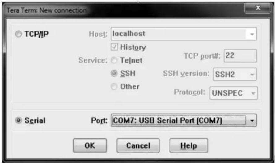
Start a terminal emulation program, such as Tera Term Pro. Configure the COM port intended for use by following these settings: 115.2 Kbps, 8, NONE, 1. Using the included RJ45 to DB9 cable (part number 73-1243), connect your PC to the PDU's CONFIG port. When the login prompt appears, login as localadmin / localadmin. When the Menu appears, navigate to "3- Network Configuration", then to "1- IP Configuration". The assigned IP address will be displayed. After you have determined the IP address, proceed to the Test Network
Connection section.
Note: You may wish to request a long-term lease period for the IP address, depending on your application.
Note: PowerAlert Device Manager and the Web Management Card support both IPv4 and IPv6. The card is set up by default to receive a DHCP address for IPv4, IPv6 or both. Receiving both addresses allows connection to the card via either the IPv4 or IPv6 address.
Installation
Static IP Address Assignment / Terminal Menu Configuration Settings

Determine IP Information: The Web management card can support a single static IPv4 address (requires setting the IP address, subnet mask and gateway) and/or a single static IPv6 address. In addition, the Web management card can support a single static IPv4 or an IPv6 DNS address that is required to be entered.

Configure Terminal Emulation Program: Set your terminal emulation program to use the COM port with its corresponding USB port.

Select Option 3: IPv4 setting, or Option 4: IPv6 settings. Select Option 1: Method. Select Option 2: Static.
Assign the address, subnet mask, gateway, etc. Save your settings by selecting "A" (apply). Choose "y" to restart PowerAlert now. Close your terminal session.

Remove Cable: Remove the cable and proceed to the Test Network Connection section.
Installation
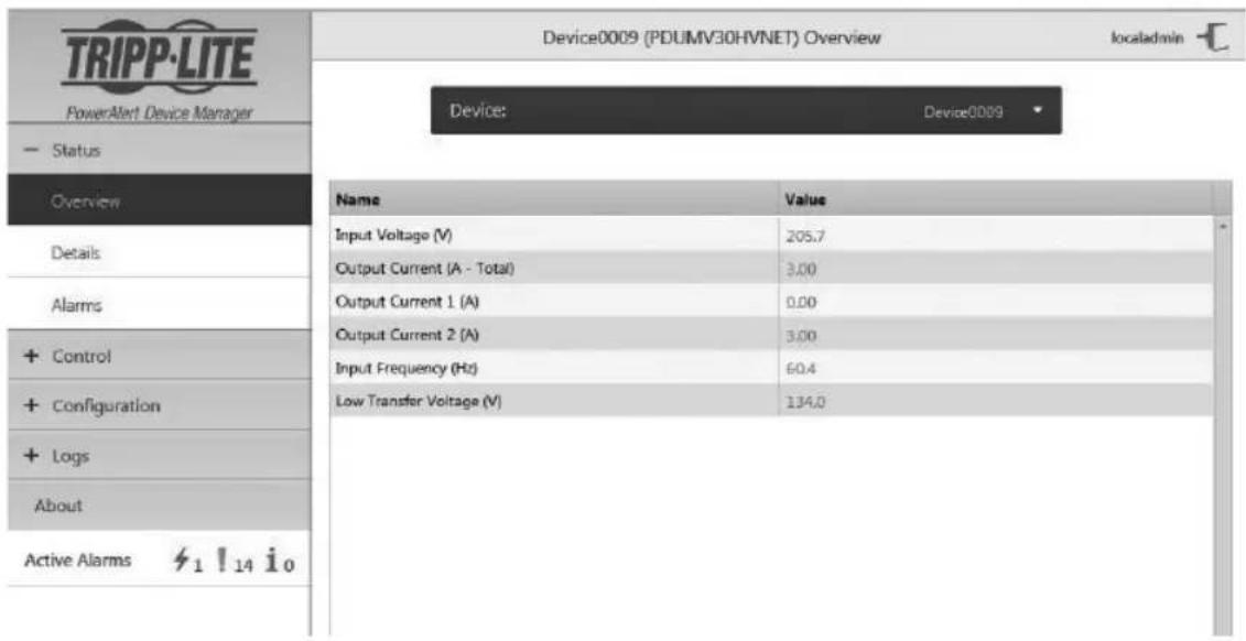
Testing Network Connection

Test Network Connection: After an IP address has been assigned to the card, try to access it with a Web browser. Open Firefox or Chrome on a computer connected to the network and enter http:// or https:// followed by the IP address. The login screen for PowerAlert Device Manager will display. The default user name is localadmin and the password is localadmin. After you enter the user name and password, the PowerAlert Device Manager Overview page will appear in the browser window. For more information about configuration and operation of the managed device, refer to the LX Platform User's Guide located in the support section of the product web page.
Features
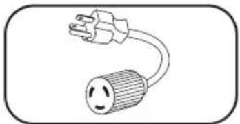
natural_image
Simple line drawing of an electrical plug with a smiling face and cord (no text or symbols)Input Plug Adapter (Select Models): Converts the PDU's twist-lock input plug to a straight-blade input plug.
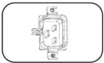
natural_image
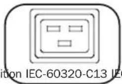
Line drawing of a wall-mounted electrical socket or socket with mounting holes (no text or symbols)Power Inlet (Select Models): The IEC power inlet connects to the included power cord or a compatible user-supplied power cord. The inlet includes a bracket to secure the cord connection.

natural_image
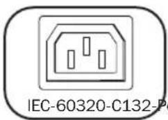
Simple line drawing of a circular connector or socket with three holes, enclosed in a rounded rectangle (no text or symbols)IEC 309 3-Pole Input Plug: Available on select models.
natural_image
Simple line drawing of two identical electrical socket sockets (no text or symbols)Outlets (Vary by Model): During normal operation, the outlets distribute AC power to connected equipment. Select models feature an LED that indicates outlet status.
natural_image
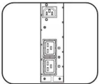
Diagram of a vertical rack-mounted device with multiple slots and mounting holes (no text or labels)Outlet LEDs: On switched models, each outlet LED illuminates when the associated outlet is ready to distribute live AC power.
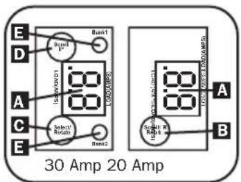
Digital Load Meter (Ammeter): The total connected equipment load in amperes is displayed by the digital meter A. 20-amp models feature a Scroll IP/Rotate Switch B. Press this switch for one second to display the PDU's IP address (two characters at a time). Press for two seconds to rotate the LED display for ease of reading in vertical installations with the input cord at the top or bottom of the PDU. 30-amp models feature a Select/Rotate Switch C and a dedicated Scroll IP Switch D. Press the Select/Rotate Switch once to display the total load (in amps) on the PDU. Press again to display the load on Bank 1 of the PDU and again to display the load on Bank 2. The Load Bank LEDs E will indicate display status as follows. Both outlet bank LEDs illuminated: total PDU load displayed. Bank 1 or Bank 2 LED illuminated: load on corresponding load bank displayed. Press the Select/Rotate Switch for two seconds to rotate the LED display for ease of reading in vertical installations with the input cord at the top or bottom of the PDU.
Features
natural_image
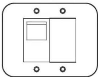
Simple diagram of a rectangular box with two side rectangles and four corner holes, enclosed in a rounded rectangle (no text or symbols)Circuit Breakers (Select Models): If the connected equipment load on a load bank exceeds the Maximum Load Rating of the load bank, the circuit breaker will trip. Disconnect excess equipment and switch breaker to the on position to reset the breaker. Models with multiple outlet banks have a circuit breaker for each bank. Circuit breakers are only used to protect output load banks.
natural_image
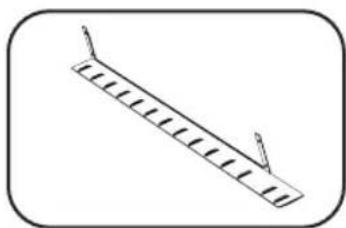
Simple line drawing of a ruler with measurement markings and a pointer (no text or symbols)Cord Retention Bracket (Select Models): Provides secure attachment points for connected equipment cords.
natural_image
Technical line drawing of a hexagonal mechanical component with a handle (no text or symbols)C14 Plug-Lock Inserts (Optional): Use the included C14 plug-lock inserts to secure plugs to C13 receptacles. Attach the sleeve to the plug making sure the pull tabs remain outside the plug and that the fit is secure. To unplug equipment properly, use the pull tabs to remove the plug and insert from the receptacle.
natural_image
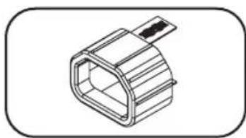
Isometric line drawing of a rectangular connector or housing (no text or symbols)C20 Plug-Lock Inserts (Optional): Use the included C20 plug-lock inserts to secure plugs to C19 receptacles. Attach the sleeve to the plug making sure the pull tabs remain outside the plug and that the fit is secure. To unplug equipment properly, use the pull tabs to remove the plug and insert from the receptacle.
natural_image
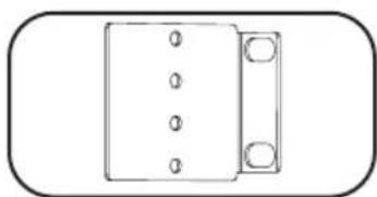
Simple line drawing of a rectangular object with four circular holes and two small circular holes on top, enclosed in a rounded rectangle (no text or symbols)Mounting Brackets: Use these brackets to mount the PDU.
natural_image
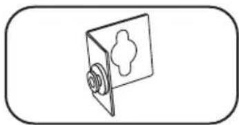
Simple line drawing of a door with a handle and screw, enclosed in a rounded rectangle (no text or symbols)PDUMVROTATEBRKT Mounting Accessory: Use these V-shaped brackets to mount the PDU with its outlets facing the rear of the rack.
Features
Web Management Card
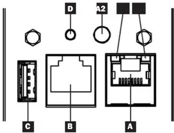
A Ethernet Port: RJ45 jack connects the WEBCARDLX to the network using a standard Ethernet patch cable. LEDs A1 and A2 indicate the operating conditions (shown in the table below).
B RJ45 Configuration Port: Use this port to provide a direct terminal connection to a computer with a terminal emulation program. An RJ45 to DB9 cable (part number 73-1243) is included with the PDU. To request a replacement cable, visit www.tripplite.com for ordering information.
USB Type-A Port: Use this port to connect a Tripp Lite EnviroSense2 module (E2MT, E2MTDO, E2MTDI, E2MTHDI) for a variety of environmental monitoring and control options. See www.tripplite.com for more information about these modules.
Note: Do not connect a keyboard or mouse to this port.
D Reset Button: Accessible through a small hole on the faceplate above the RJ45 Configuration Port. Press once to reset the Web Management Card. Press and hold for 15 seconds to reset the Web Management Card to factory default settings.
Note: PDU loads will not be affected.
E Status LED: Shows Web Management Card status (shown in the table below).
| Identifier | LED Function LED | Color Status | Description | |
| A1 | Ethernet Link/Activity Indicator | Green Flashing | There is network activity on the port | |
| Off | There is no network activity on the port | |||
| A2 | Ethernet Network Speed Indicator | Yellow On steady 100 Mbps network speed | ||
| E | Web Management Card Status | Green On steady Normal operation | ||
| Green Single flash | Power up indicator | |||
| Green/Orange | Off No power or card is initializing | |||
| Green/Orange | Alternating (~1/sec.) | Software update in progress | ||
| Green/Orange | Alternating (~2/sec.) | Restoring factory default configuration | ||
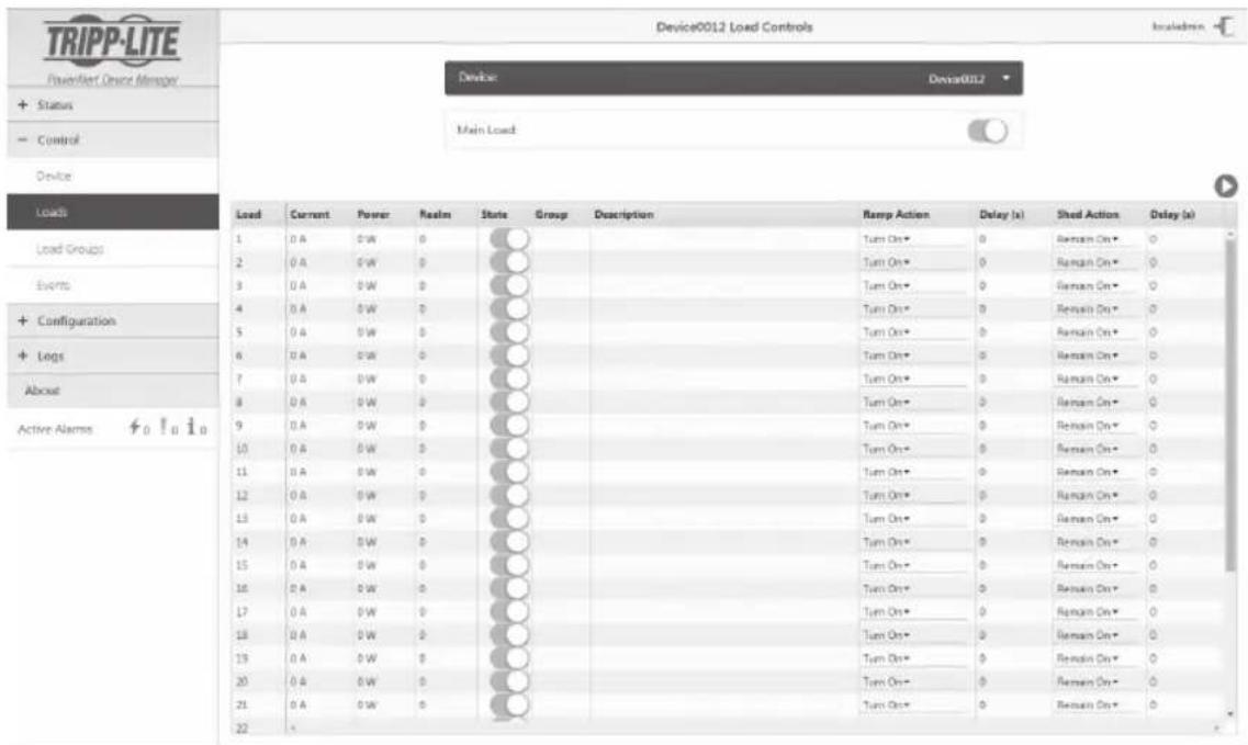
Configuration and Operation
Remote Monitoring and Control
The PDU provides remote monitoring, outlet control and more via Web browser, telnet and SNMP-based Network Management Systems. For more information about configuration and operation of the PDU via the PowerAlert Device Manger, refer to the LX Platform User's Guide User's Guide, which can be found by going to www.tripplite.com/support and typing LX Platform in the search field.
Service
Your Tripp Lite product is covered by the warranty described in this manual. A variety of Extended Warranty and On-Site Service Programs are also available from Tripp Lite. For more information on service, visit www.triplite.com/support. Before returning your product for service, follow these steps: 1. Review the installation and operation procedures in this manual to insure that the service problem does not originate from a misreading of the instructions. 2. If the problem continues, do not contact or return the product to the dealer. Instead, visit www.tripplite.com/support. 3. If the problem requires service, visit www.triplite.com/support and click the Product Returns link. From here you can request a Returned Material Authorization (RMA) number, which is required for service. This simple on-line form will ask for your unit's model and serial numbers, along with other general purchaser information. The RMA number, along with shipping instructions will be emailed to you. Any damages (direct, indirect, special or consequential) to the product incurred during shipment to Tripp Lite or an authorized Tripp Lite service center is not covered under warranty. Products shipped to Tripp Lite or an authorized Tripp Lite service center must have transportation charges prepaid. Mark the RMA number on the outside of the package. If the product is within its warranty period, enclose a copy of your sales receipt. Return the product for service using an insured carrier to the address given to you when you request the RMA.Warranty and Product Registration
LIMITED WARRANTY
Seller warrants this product, if used in accordance with all applicable instructions, to be free from original defects in material and workmanship for a period of 2 years (except internal UPS system batteries outside USA and Canada, 1 year) from the date of initial purchase. If the product should prove defective in material or workmanship within that period, Seller will repair or replace the product, in its sole discretion. Service under this Warranty can only be obtained by your delivering or shipping the product (with all shipping or delivery charges prepaid) to: Tripp Lite, 1111 W. 35th Street, Chicago, IL 60609 USA. Seller will pay return shipping charges. Visit www.tripplite.com/support before sending any equipment back for repair. THIS WARRANTY DOES NOT APPLY TO NORMAL WEAR OR TO DAMAGE RESULTING FROM ACCIDENT, MISUSE, ABUSE OR NEGLECT. SELLER MAKES NO EXPRESS WARRANTIES OTHER THAN THE WARRANTY EXPRESSLY SET FORTH HEREIN. EXCEPT TO THE EXTENT PROHIBITED BY APPLICABLE LAW, ALL IMPLIED WARRANTIES, INCLUDING ALL WARRANTIES OF MERCHANTABILITY OR FITNESS, ARE LIMITED IN DURATION TO THE WARRANTY PERIOD SET FORTH ABOVE; AND THIS WARRANTY EXPRESSLY EXCLUDES ALL INCIDENTAL AND CONSEQUENTIAL DAMAGES. (Some states do not allow limitations on how long an implied warranty lasts, and some states do not allow the exclusion or limitation of incidental or consequential damages, so the above limitations or exclusions may not apply to you. This Warranty gives you specific legal rights, and you may have other rights which vary from jurisdiction to jurisdiction). WARNING: The individual user should take care to determine prior to use whether this device is suitable, adequate or safe for the use intended. Since individual applications are subject to great variation, the manufacturer makes no representation or warranty as to the suitability or fitness of these devices for any specific application.PRODUCT REGISTRATION
Visit www.triplite.com/warranty today to register your new Tripp Lite product. You'll be automatically entered into a drawing for a chance to win a FREE Tripp Lite product!\* \* No purchase necessary. Void where prohibited. Some restrictions apply. See website for details.FCC Notice, Class A
This device complies with part 15 of the FCC Rules. Operation is subject to the following two conditions: (1) This device may not cause harmful interference, and (2) this device must accept any interference received, including interference that may cause undesired operation. Note: This equipment has been tested and found to comply with the limits for a Class A digital device, pursuant to part 15 of the FCC Rules. These limits are designed to provide reasonable protection against harmful interference when the equipment is operated in a commercial environment. This equipment generates, uses, and can radiate radio frequency energy and, if not installed and used in accordance with the instruction manual, may cause harmful interference to radio communications. Operation of this equipment in a residential area is likely to cause harmful interference in which case the user will be required to correct the interference at his own expense. The user must use shielded cables and connectors with this equipment. Any changes or modifications to this equipment not expressly approved by Tripp Lite could void the user's authority to operate this equipment.Regulatory Compliance Identification Numbers
For the purpose of regulatory compliance certifications and identification, your Tripp Lite product has been assigned a unique series number. The series number can be found on the product nameplate label, along with all required approval markings and information. When requesting compliance information for this product, always refer to the series number. The series number should not be confused with the marketing name or model number of the product. Tripp Lite has a policy of continuous improvement. Specifications are subject to change without notice.   1111 W. 35th Street, Chicago, IL 60609 USA • www.tripplite.com/support 21-03-417 93-3667\_RevDManual del propietario
PDUs Monitoreables para Rack PDUs Controlables para Rack
OU (Vertical) Formato en Barra
PDUMNV20HVLX
(Modelo 208/230V 16 Amp, Monitoreada) Numero de Serie: AGPD7897PDUMV20HVNET2LX
(Modelo 208/230V 16 Amp, Controllable) Numero de Serie: AGPD7897PDUMNV30HVLX
(Modelo 208/240V 24 Amp, Monitoreada) Numero de Serie: AGPD7898PDUMV30HVNETLX
(Modelo 208/230V 24 Amp, Controllable) Numero de Serie: AGPD7898PDUMNV32HV2LX
(Modelo 200-240V 32A, Monitoreada) Numero de Serie: AG-00CAInstrucciones de seguridad importantes 14
Características de la PDU monitoreada para Rack 14
Características de la PDU controllable para Rack 15
Instalación 15
Características 20Configuración y operación 23
Servicio técnico 23
Garantía 24 English 1 Français 25 Русский 37 Deutsch 49   Excelencia en Manufactura. 1111 W. 35th Street, Chicago, IL 60609 USA • www.tripplite.com/support © 2019 Tripp Lite. Todos los derechos reservados.Instrucciones de seguridad importantes
GUARDE ESTAS INSTRUCCIONES
Este manual contiene instrucciones y advertencias que deben seguirse durante la instalación, operación y almacenamiento de este producto. De no seguirlas, se anulará la garantía del producto.  PRECAUCION Este aparato no se destina para utilizarse por personas (incluyendo niños), cuyas capacidades físicas, sensoriales o mentales sean diferentes o estén reducidas, o carezcan de experiencia o conocimiento, a menos que dichas personas reciban una supervisión o capacitación para el funcionamiento del aparato por una persona responsable de su seguridad. Los ninos deben de supervisarse para asegurar que no empleen el aparato como juguete. Nunca utilize el aparato si el cable y la clavija están dañados; si no funciona correctamente o si se ha caido o dañado, llévelo a un centro de servicio autorizado para que lo examinen y lo reparen. Si el cordon de alimentación es dañado, éste debe sustituirse por el fabricante, por su agente de servicio autorizado o por personal calificado con el fin de evitar un peligro. \- El PDU proporciona la conveniencia de múltiples tomacorrientes, pero NO proporciona protección contra sobretensión o ruido en la línea para los equipos conectados. - El PDU está diseñada solo para uso en interiores en un entorno controlado lejos de humedad excesiva, temperaturas extremas, contaminantes conductivos, polvo o luz del sol directa. \- Mantiene la temperatura ambiente interior entre 0°C y 50°C. \- El PDU debe ser instalado solamente por un técnico calificado. \- No intente instalar el PDU en una superficie inestable o no segura. \- Instale de acuerdo con los reglamentos eléctricos locales. Asegúrese de usar para la instalación la protección adecuada contra sobrecorriente, de acuerdo con la especificación de la clavija o del equipo. \- Conecte el PDU a un tomacorriente que esté de acuerdo a los códigos locales de construcción y que esté correctamente protegido contra corrientes excesivas, cortocircuitos y fallas de conexión a tierra. \- Los tomacorrientes eléctricos que suministran energía al equipo deben instalarse próximos al equipo y ser fácilmente accesibles. \- No conecte El PDU a un toma corriente que no esté a tierra o cables de extensión o adaptadores que eliminen la conexión a tierra. \- Asegúrese de proporcionar un dispositivo local de desconexión, que sea fácilmente accesible, en cualquier modelo que esté instalado permanentemente sin una clavija. \- Nunca intente instalar equipos eléctricos durante una tormenta eléctrica. \- El equipo individual conectado al PDU no debe consumir más corriente que la de la especificación de cada tomacorriente individual del PDU. \- La carga total conectada al PDU no debe exceder la capacidad de carga máxima del PDU. \- No intente modificar el PDU, las clavijas de entrada o los cables de alimentación. \- No perfore ni intente abrir ninguna parte del gabinete del PDU. No tiene partes a las que el usuario pueda dar servicio. \- No intente usar el PDU si se daña cualquier parte. \- No se recomienda el uso de este equipo en aplicaciones de soporte de vida en donde la falla de este equipo pueda consecuentemente causar la falla del equipo de soporte de vida o afectar significativamente su seguridad o efectividad.Características de la PDU Monitoreada para Rack
\- La interfaz de red permite el monitoreo remoto de energía y la notificación del suceso. \- Medidor digital en amperios para el monitoreo de la carga en el sitio. \- Módulos opcionales de EnviroSense2 (E2MT, E2MTDO, E2MTDI, E2MTHDI) permiten una variedad de opciones de monitoreo y control ambientales. Para más información acerca de estos módulos, consulte www.tripplite.com. \- Instalación sin herramientas con montaje por botones en gabinetes Tripp Lite SmartRack® y muchos otros de terceros.Características alternas de la PDU para Rack
- La interfaz de red permite el monitoreo remoto de la energía y el control individual del tomacorriente. - Los tomacorrientes controlables individualmente permiten el reinicio remoto de los dispositivos de red bloqueados. - Medidor digital en amperios para monitoreo de la carga en el sitio. - Módulos opcionales de EnviroSense2 (E2MT, E2MTDO, E2MTDI, E2MTHDI) permiten una variedad de opciones de monitoreo y control ambientales. Para más información acerca de estos módulos, consulte www.tripplite.com. - Instalación sin herramientas con montaje por botones en gabinetes Tripp Lite SmartRack® y muchos otros de terceros.Instalación
Montaje del PDU
Nota: Las ilustraciones pueden ser un poco diferentes a las de su modelo de PDU. Independientemente de la configuración, el usuario debe determinar la idoneidad de los materiales y accesorios así como de los procedimientos antes del montaje. El PDU y el material incluido están diseñados para racks (bastidores) y cajas de rack (bastidor) comunes, y pueden no ser apropiados para todas las aplicaciones. Se incluyen los tornillos para fijar los soportes de montaje y la repisa para el retención de cables al PDU. Use únicamente los tornillos suministrados por el fabricante o su equivalente exacto (#6-32, ¼ pulg. de cabeza plana). Si instala la PDU en un rack que tiene ranuras de montaje de botón, solo necesita realizar el paso 1-1. Si su rack no tiene ranuras de montaje de botón, proceda con el paso 1-2.  Para instalar la PDU en un rack equipado con ranuras de montaje de botón, inserte los botones de montaje en la parte trasera de la PDU dentro de las ranuras de montaje de botón sobre el rack, y deslice la PDU hacia abajo hasta que los botones de montaje enganchen en la sección estrecha de las ranuras de montaje de botón. Nota: Para instalar la PDU en un rack equipado con ranuras de montaje de botón, inserte los botones de montaje en la parte trasera de la PDU dentro de las ranuras de montaje de botón sobre el rack, y deslice la PDU hacia abajo hasta que los botones de montaje enganchen en la sección estrecha de las ranuras de montaje de botón. Para una imagen, consulte la sección Características. natural_image
Simple line drawing of a device casing with a circular component and rectangular cutouts (no text or symbols)Instalación
Conexión del PDU
2-1
(Únicamente modelos con una entrada de corriente IEC o enchufe de entrada de 3 polos IEC 309) Modelos selectos tienen un cable de alimentación desprendible. Fije el cable de alimentación, incluido, al PDU insertando el conector IEC A del cable de alimentación en la entrada de corriente IEC B localizada cerca del extremo del PDU. Use las abrazaderas incluidas C para asegurar la conexión del cable de alimentación.  Nota: Opcionalmente, un cable de alimentación, suministrado por el usuario puede fijarse al PDU conectándolo a la entrada IEC. No intente conectar un cable suministrado por el usuario a menos que esté certificado como compatible con la fuente de energía de entrada que será usada con el PDU.2-2
(Opcional - únicamente modelos con adaptador de clavija) Modelos selectos incluyen un adaptador de clavija de entrada que convierte la clavija de entrada de media vuelta a una clavija de entrada de pala recta. Conecte el adaptador de la clavija de entrada A a la clavija de entrada B si desea enchufar el PDU a una toma de corriente de pala recta compatible.2-3
Conecte la clavija de entrada a una toma de corriente CA compatible. Si el PDU no tiene un interruptor de circuitos, debe colocársele un dispositivo de protección contra sobre corriente que tenga el mismo amperaje del PDU. Nota: La fuente de energía CA no debe compartir un circuito con una carga eléctrica grande.  natural_image
Line drawing of a plug inserted into an electrical socket (no text or symbols)2-4
(Opción 1 - Modelos selectos solamente) Si fijo las abrazaderas de retención del cable, sujete cada cable de alimentación de cada equipo a la abrazadera de retención. Sujete cada cable a la bandeja de retención enrollando el cable y asegurándolo con uno de los sujetadores de cable incluidos A. Asegúrese de que cada pueda ser desenchufado del PDU sin quitar el sujetador del cable. (Opción 2) Use los insertos de seguridad de clavija C14 y C20 incluidos  para asegurar las clavijas a los contactos. Instale el manguito a la clavija, asegurando que las lengüetas de tiro B permanezcan fuera de la clavija y que la sujeción esté segura. Para desenchufar correctamente el equipo, use las lengüetas de tiro para retirar la clavija e inserto del contacto.Instalación
 Conecte las clavijas de entrada de su equipo A a las tomas de corriente B del PDU. El LED C junto a cada toma de corriente se iluminará cuando la toma de corriente esté lista para distribuir energía CA viva (Únicamente Modelos Controlables). El lector digital de carga D muestra la carga total del equipo conectado en amperes. (Modelos selectos proporcionan información adicional. Vea la sección Características para mayor información.) Nota: A fin de minimizar la interferencia entre los dispositivos conectados, conecte cada dispositivo a la toma de corriente del PDU más cercana y enrolle el cable excedente.  (La configuración puede variar con el modelo.)Conectando Su PDU a la Red
Nota: La dirección MAC (Media Access Control / Control de Acceso de Medios) del PDU (una serie de 12-dígitos en este formato: 00 06 67 XX XX XX) está impresa en una etiqueta adherida al gabinete del PDU. Si el DHCP (Dynamic Host Configuration Protocol / Protocolo Dinámico de la Configuración del Anfitrión) de su servidor de red asignará una dirección dinámica al PDU automáticamente, vaya al Paso 3-1. Si Usted asignará manualmente una dirección estática al PDU vaya al Paso 4-1. Si no está seguro que método utilizar contacte a su administrador de red para obtener asistencia antes de continuar con el proceso de instalación.Dynamic IP Address Assignment
Conecte a la Red la Tarjeta para
Administración de Red: Conecte un cable patch estándar para Ethernet al puerto de Ethernet RJ45 en su Tarjeta para Administración de Red. Nota: Este puerto no admite aplicaciones de PoE (Energía sobre la Ethernet). La tarjeta intentará obtener una dirección IP mediante DHCP. Esto puede tomar unos minutos, dependiendo de su entorno de red. natural_image
Diagram of a device with three ports and a lever, no text or symbols presentInstalación
Asignación de una Dirección IP Estática / Parámetros de Configuración del Menú de Terminal
4-1 Determine la Información de IP: La Tarjeta para Administración de Web puede soportar una dirección IPv4 estática sencilla (requiere configurar la dirección IP, la máscara de subred y el portal) y/o una dirección estática IPv6 sencilla. Además la Tarjeta para Administración de Web puede soportar una dirección DNS IPv4 o IPv6 estática sencilla que se requiere ingresar. 4-2 Configure el Programa de Emulación de Terminal: Configure su programa de emulación de terminal para utilizar el puerto COM con su puerto USB correspondiente.  4-3 Seleccione Opción 3: Parámetro IPv4, o Opción 4: Parámetros IPv6. Seleccione Opción 1: Método. Seleccione Opción 2: Estática. Asigne la dirección, máscara de subred, portal, etc. Guarde sus parámetros seleccionando "A" (aplicar). Elija "y" para reiniciar ahora PowerAlert. Elija su sesión de terminal. 4-4 Retire el Cable: Retire el cable y proceda a la sección de Probar Conexión de Red.Instalación
Conectando Su PDU a la Red
 Pruebe la Conexión de Red: Después que se ha asignado una dirección IP a la tarjeta, intente acceder a ella usando un navegador de Web. Abra Firefox o Chrome en una computadora conectada a la red e ingrese a http:// o https:// seguido por la dirección IP. Se mostrará la pantalla de inicio de sesión para el Administrador de Dispositivo PowerAlert. El nombre de usuario Predeterminado es localadmin y la contraseña es localadmin. Después de introducir el nombre de usuario y la contraseña, la página Visión General del Administrador de dispositivos de PowerAlert aparecerá en la ventana del navegador. Para obtener más información sobre la configuración y operación del dispositivo administrado, consulte la Guía del Usuario de la Plataforma LX, ubicada en la sección soporte de la página web del producto. Características
natural_image
Simple line drawing of an electrical plug with a smiling face and cord (no text or symbols)Adaptador de Clavija de Entrada (Modelos Selectos):
Convierte la clavija de entrada de media vuelta a una clavija de entrada de pala recta. natural_image
Line drawing of a wall-mounted electrical socket or socket with mounting holes (no text or symbols)natural_image
Simple line drawing of a circular connector or socket with three holes, enclosed in a rounded rectangle (no text or symbols)natural_image
Simple line drawing of two identical electrical socket sockets (no text or symbols)natural_image
Diagram of a vertical rack-mounted device with multiple slots and mounting holes (no text or labels)Características
natural_image
Simple diagram of a rectangular box with two side rectangles and four corner holes, enclosed in a rounded rectangle (no text or symbols)Interruptores de Circuitos de Salida (Modelos Selectos):
Si la carga de los equipos conectados en un banco de carga excede la Carga nominal máxima del banco de carga, se disparará el interruptor de circuitos. Desconecte el equipo en exceso y coloque el interruptor del interruptor de circuitos en la posición "ON" para reestablecerlo. Los modelos con bancos con múltiples tomacorrientes tienen un interruptor de circuito para cada banco. Los interruptores de circuito se usan solamente para proteger los bancos de carga de salida. natural_image
Simple line drawing of a ruler with tick marks and a small protrusion at the end (no text or symbols)Soportes para Retención de Cable (Modelos Selectos):
Proporciona puntos de sujeción seguros para los cables del equipo conectado. natural_image
Technical line drawing of a hexagonal mechanical component with a protruding rod (no text or symbols)natural_image
Isometric line drawing of a mechanical component with no text or symbolsnatural_image
Simple line drawing of a rectangular object with four circular holes and two small square holes, enclosed in a rounded rectangle (no text or symbols)natural_image
Simple line drawing of a 3D box with a circular element on top, enclosed in a rounded rectangle (no text or symbols)Características
Tarjeta para Administración de Red
 A Puerto Ethernet: El conector RJ45 conecta la tarjeta WEBCARDLX a la red usando un cable patch estándar de Ethernet. Los LEDs A1 y A2 indican las condiciones de operación (se muestra en la siguiente tabla). B Puerto de Configuración RJ45: Use este puerto para proporcionar una conexión directa de terminal a una computadora con un programa de emulación de terminal. Se incluye con el PDU un cable RJ45 a DB9 (número de parte 73-1243). Para solicitar un cable de reemplazo, visite www.triplite.com para obtener información acerca de pedidos. Puerto USB Tipo A: Use este puerto para conectar un módulo opcional EnviroSense2 (E2MT, E2MTDO, E2MTDI, E2MTHDI) de Tripp Lite para una gran variedad de opciones de monitoreo y control ambiental. Para más información acerca de estos módulos, consulte www.triplite.com. Nota: No conecte un teclado o mouse a este puerto. Botón de Restaurar: Accesible a través de un pequeño orificio en la placa frontal sobre el Puerto de Configuración RJ45. Oprima una vez para restaurar la Tarjeta para Administración de Red. Oprima y sostenga por 15 segundos para restaurar la Tarjeta para Administración de Red a la configuración predeterminada de fábrica. Nota: Las cargas del PDU no se afectarán. E LED de Estado: Muestra el estado de la Tarjeta para Administración de Red (se muestra en la tabla siguiente).| Identificador | Función del LED | Color del LED | Estado Descripción | |
| A1 | Indicador de Actividad / Enlace de Ethernet | Verde Destellando | do Hay actividad | de red en el puerto |
| Apagado No hay actividad de red en el puerto | ||||
| A2 | Indicador de Velocidad de Red Ethernet | Amarillo Encendido permanente | Velocidad de red de 100 Mbps | |
| Si A1 está destellando la velocidad es de 10 Mbps | ||||
| Si A1 está también apagado no hay actividad de red | ||||
| E | Estado de la Tarjeta para Administración de Red | Verde Encendido permanente | Operación normal | |
| Verde | Un solo Destello | Indicador de encendido | ||
| Verde / Anaranjado | Apagado Sin energía o la tarjeta está iniciando | |||
| Verde / Anaranjado | Alternando (~1/s) | Actualización de software en progreso | ||
| Verde / Anaranjado | Alternando (~2/s) | Restaurando la configuración predeterminada de fábrica | ||
Configuración y operación
Control y monitoreo remotol
El PDU proporciona monitoreo remoto, control de los tomacorrientes y más mediante un navegador de Internet, telnet y sistemas de administración de red basados en SNMP. Para obtener más información sobre la configuración y operación del PDU mediante la el Administrador de Dispositivo PowerAlert, consulte la Guía del Usuario de la Plataforma LX visitando www.triplite.com/support y escribiendo LX Platform en el campo de búsqueda. Servicio técnico
Su producto Tripp Lite está cubierto por la garantía descrita en este manual. Tripp Lite también pone a su disposición una variedad de Garantías extendidas y Programas de servicio técnico en el sitio. Si desea más información sobre el servicio técnico, visite www.triplite.com/support. Antes de devolver su producto para servicio técnico, siga estos pasos: 1. Revise la instalación y los procedimientos de operación que se encuentran en este manual para asegurarse de que el problema de servicio no se debe a una mala lectura de las instrucciones. 2. Si el problema persiste, no se comunique ni devuelva el producto al mayorista. En cambio, visite www.triplite.com/support. 3. Si el problema exige servicio técnico, visite www.triplite.com/support y haga clic en el enlace Devoluciones de productos. Desde aquí puede solicitar un número de Autorización de Material Devuelto (RMA), que se necesita para el servicio técnico. En este sencillo formulario en línea se le solicitarán los números de serie y modelo de la unidad, junto con otra información general del comprador. El número RMA y las instrucciones para el envío se le enviarán por correo electrónico. La presente garantía no cubre ningún daño (directo, indirecto, especial o consecuencial) del producto que ocurra durante el envío a Tripp Lite o a un centro de servicio técnico de Tripp Lite autorizado. Los productos enviados a Tripp Lite o a un centro de servicio técnico de Tripp Lite autorizado deben tener prepagos los cargos de transporte. Escriba el número RMA en el exterior del embalaje. Si el producto se encuentra dentro del período de garantía, adjunte una copia de su recibo de venta. Envíe el producto para servicio técnico mediante un transportador asegurado a la dirección que se le proporcionó cuando solicitó el número RMA.Garantía
LIMITED WARRANTY
El vendedor garantiza que este producto, si se emplea de acuerdo con todas las instrucciones aplicables, no tendrá defectos en materiales ni mano de obra por un período de 2 años (salvo para baterías internas del UPS fuera de EE.UU. y Canadá, 1 año) a partir de la fecha de compra. Si se verifica que el producto tiene defectos en los materiales o en la mano de obra dentro de dicho período, el vendedor reparará o reemplazará el producto, a su sola discreción. Sólo puede obtenerse servicio bajo esta garantía, entregando o despachando el producto (con todos los cargos de despacho o entrega pagados por adelantado) a: Tripp Lite, 1111 W. 35th Street, Chicago, IL 60609 USA. El vendedor pagará los cargos de despacho del retorno. Visite www.triplite.com/support antes de enviar algún equipo para reparación. ESTA GARANTÍA NO SE APLICA AL DESGASTE NORMAL O A DAÑOS RESULTANTES DE UN ACCIDENTE, USO INADECUADO, MALTRATO O NEGLIGENCIA. EL VENDEDOR NO EXPRESA NINGUNA OTRA GARANTÍA DISTINTA DE LA ESTABLECIDA EN ESTE DOCUMENTO EN FORMA EXPLÍCITA. EXCEPTO HASTA EL GRADO PROHIBIDO POR LAS LEYES APLICABLES, TODAS LAS GARANTÍAS IMPLÍCITAS, INCLUYENDO TODAS LAS GARANTÍAS DE COMERCIABILIDAD O IDONEIDAD, ESTÁN LIMITADAS EN DURACIÓN AL PERÍODO DE GARANTÍA ESTABLECIDO ANTERIORMENTE; ESTA GARANTÍA EXCLUYE EXPRESAMENTE TODOS LOS DAÑOS INCIDENTALES Y CONSECUENTES. (Algunos estados no permiten limitaciones sobre la duración de una garantía implícita, y algunos estados no permiten la exclusión o limitación de daños incidentales o consecuentes, de modo que las limitaciones o exclusiones mencionadas pueden no aplicarse a usted. Esta garantía le da derechos legales específicos, pero usted puede tener otros derechos que varían de jurisdicción a jurisdicción.) ADVERTENCIA: El usuario individual debe encargarse de determinar antes de usarlo, si este dispositivo es apropiado, adecuado o seguro para el uso proyectado. Ya que las aplicaciones individuales están sujetas a gran variación, el fabricante no declara ni garantiza la idoneidad o aptitud de estos dispositivos para ninguna aplicación específica.Cumplimiento de las normas de los números de identificación
Para fines de identificación y certificación del cumplimiento de las normas, su producto Tripp Lite tiene asignado un número de serie único. Puede encontrar el número de serie en la etiqueta de la placa de identificación del producto, junto con los símbolos de aprobación e información requeridos. Al solicitar información sobre el cumplimiento de las normas para este producto, siempre mencione el número de serie. El número de serie no debe ser confundido con el nombre de identificación ni con el número de modelo del producto. Tripp Lite tiene una política de mejora continua. Las especificaciones están sujetas a cambio sin previo aviso.   1111 W. 35th Street, Chicago, IL 60609 USA • www.tripplite.com/support 21-03-417 93-3667 RevDManuel du propriétaire
PDU en bâti surveillée
Unité de distribution
d'alimentation (PDU)
en baie commandée par interrupteur
Format barrette de connexion OU (Vertical)
PDUMNV20HVLX
(modèle de 208/230 V 16 ampères, surveillée) Numéro de série : AGPD7897PDUMV20HVNET2LX
(modèle de 208/230 V 16 ampères, liaison commutée) Numéro de série : AGPD7897PDUMNV30HVLX
(modèle de 208/240 V 24 ampères, surveillée) Numéro de série : AGPD7898PDUMV30HVNETLX
(modèle de 208/230 V 24 ampères, liaison commutée) Numéro de série : AGPD7898PDUMNV32HV2LX
(modèle de 208/240 V 32 ampères, surveillée) Numéro de série : AG-00CA Importantes consignes de sécurité 26 Caractéristiques de la PDU en bâti surveillée 26 Caractéristiques de la PDU en bâti à liaison commutée 27 Installation 27 Caractéristiques 31 Configuration et fonctionnement 35 Entretien 35 Garantie 36 English 1 Español 13 Русский 37 Deutsch 49   D'excellence Industrielle. 1111 W. 35th Street, Chicago, IL 60609 USA • www.tripplite.com/support Copyright © 2019 Tripp Lite. Tous droits réservés.Importantes consignes de sécurité
CONSERVER CES DIRECTIVES
Ce manuel contient des instructions et des mises en garde que vous devez respecter durant l'installation, l'utilisation et l'entreposage de ce produit. Le non-respect de ces instructions et mises en garde annulera la garantie du produit.  - La PDU fournit des prises multiples pratiques, mais elle ne FOURNIT PAS de protection contre les surtensions ou les bruits de ligne pour l'équipement connecté. - La PDU est conçue pour être utilisée à l'intérieur uniquement, dans un environnement contrôlé, à l'écart de l'excès d'humidité, des températures extrêmes, des contaminants conducteurs, de la poussière et de la lumière directe du soleil. - Maintenir la température intérieure ambiante entre 0 °C et 50 °C. - La PDU doit être installée par un technicien qualifié seulement. - Ne pas tenter de monter la PDU sur une surface précaire ou instable. - Installer conformément aux codes locaux de l'électricité. S'assurer d'utiliser la bonne protection contre les surintensités pour l'installation, conformément aux valeurs nominales de la fiche et de l'équipement. - Branchez la PDU à une prise de courant à une prise de courant qui est conforme aux codes de bâtiment locaux et qui est dûment protégée contre les courants excessifs, les courts-circuits et les défauts à la terre. - Les prises électriques qui alimentent l'équipement doivent être installées à proximité de l'équipement et être facilement accessibles. - Ne pas connecter la PDU dans une prise non mise à la masse ou des rallonges électriques ou des adaptateurs qui éliminent la connexion à la masse. - S'assurer de fournir un dispositif de déconnexion local pour tous les modèles qui sont installés en permanence sans fiche facilement accessible. - Ne jamais essayer d'installer un équipement électrique pendant un orage. - L'équipement individuel connecté à la PDU ne doit pas excéder la charge nominale des prises individuelles de la PDU. - La charge totale connectée à la PDU ne doit pas excéder la charge nominale maximum pour la PDU. - Ne pas tenter de modifier la PDU, y compris les fiches d'entrée et les câbles d'alimentation. - Ne pas percer ou tenter d'ouvrir une quelconque partie du boîtier de la PDU. Il n'existe aucune pièce réparable par l'utilisateur à l'intérieur. - Ne pas tenter d'utiliser la PDU si une de ses pièces est endommagée. - Il n'est pas recommandé d'utiliser cet équipement dans les applications de soutien vital où une panne de cet équipement serait susceptible de causer une panne de l'équipement de soutien vital ou d'affecter sérieusement sa sécurité ou son efficacité.Caractéristiques de la PDU en bâti surveillée
- L'interface réseau permet la surveillance à distance de l'alimentation et de la notification d'événements. - Ampèremètre numérique pour la surveillance de la charge sur le site. - Les modules EnviroSense2 en optionnels (E2MT, E2MTDO, E2MTDI, E2MTHDI) permettent une variété d'options de surveillance environnementale et de gestion. Visitez www.tripplite.com pour des informations supplémentaires sur ces modules. - Installation avec bouton de montage sans outil dans le SmartRack® de Tripp Lite et plusieurs boîtiers tiers.Caractéristiques de la PDU en bâti à liaison commutée
- L'interface réseau permet la surveillance à distance de l'alimentation et le contrôle individuel des prises. - Les prises contrôlables individuellement permettent le redémarrage à distance des périphériques de réseau verrouillés. - Ampèremètre numérique pour la surveillance de la charge sur le site. - Les modules EnviroSense2 en optionnels (E2MT, E2MTDO, E2MTDI, E2MTHDI) permettent une variété d'options de surveillance environnementale et de gestion. Visitez www.tripplite.com pour des informations supplémentaires sur ces modules. - Installation avec boutons de montage sans outil dans le SmartRack® de Tripp Lite et plusieurs boîtiers tiers.Installation
Montage de l'unité de distribution d'alimentation (PDU)
Remarque : Les illustrations peuvent être différentes de celles de votre modèle de PDU. Sans tenir compte de la configuration, l'utilisateur doit déterminer la compatibilité de la quincaillerie et les procédures avant d'effectuer l'installation. L'unité PDU et la quincaillerie incluse sont conçues pour des types de bâti et boîtier courants et peuvent ne pas convenir à toutes les applications. Les vis pour fixer les supports de fixation et la tablette de retenue des cordons à l'unité sont incluses. N'utilisez que les vis fournies par le fabricant ou leur équivalent exact (#6-32 de 1/4 po, à tête plate). Si la PDU est installée dans un bâti comportant des fentes pour boutons de montage, vous n'avez qu'à effectuer l'étape 1-1. Si votre armoire de bâti ne comporte pas de fentes pour boutons de montage, passez à l'étape 1-2.1-1
Pour installer la PDU dans un bâti équipé de fentes pour boutons de montage, insérez les boutons de montage à l'arrière de la PDU dans les fentes pour boutons de montage sur le bâti et glissez la PDU vers le bas jusqu'à ce que les boutons de montage soient engagés dans la section étroite des fentes pour boutons de montage. Remarque : Pour installer la PDU avec ses prises faisant face à l'arrière du bâti, utilisez l'accessoire PDUMVROTATEBRKT inclus. Ce support en forme de V offre un bouton de montage sur une patte du V et une fente pour boutons de montage sur l'autre, repositionnant efficacement les boutons de montage. Consulter la section Caractéristiques pour voir une image. natural_image
Technical line drawing of a device casing with internal components (no text or symbols)1-2
Fixer les brides de montage à l'unité de distribution.1-3
(Optionnel) fixer les brides de retenue du cordon à la PDU.1.4
Fixer la PDU à un rail vertical dans votre baie ou armoire pour baie. Utiliser le matériel de montage fourni pour fixer les supports de montage au rail. Installation
Connexion de l'unité de distribution d'alimentation (PDU)
2-1
(Modèles avec embase d'alimentation CEI ou Cordon d'entrée à 3 pôles IEC 309 uniquement) Certains modèles disposent d'un cordon d'alimentation amovible. Brancher le cordon d'alimentation fourni à la PDU en insérant le connecteur CEI A du cordon dans l'embase d'alimentation CEI B située près de l'extrémité de la PDU. Utiliser la bride fournie C pour assurer la connexion du cordon d'alimentation.  Remarque : À votre choix, un cordon d'alimentation fourni par l'utilisateur peut être branché à la PDU en le connectant à l'entrée CEI. Ne pas essayer de brancher un cordon d'alimentation fourni par l'utilisateur s'il n'est pas certifié compatible avec la source d'alimentation qui sera utilisée par la PDU.2-2
(Optionnel - modèles avec adaptateur de fiche d'entrée uniquement) Certains modèles disposent d'un adaptateur de fiche d'entrée qui convertit la fiche d'entrée à verrouillage rotatif en fiche d'entrée à lames droites. Brancher l'adaptateur de fiche d'entrée A à la fiche d'entrée B si vous désirez brancher la PDU dans une prise compatible pour lames droites.2-3
(Brancher la fiche d'entrée à une prise de courant CA compatible. Si la PDU ne dispose pas d'un disjoncteur, il faut lui fournir un dispositif de protection de surcharge qui corresponde à l'intensité nominale de la PDU. Remarque : La source d'alimentation ne doit pas partager de circuit avec une charge électrique lourde.2-4
(Option 1 - certains modèles seulement) Si vous fixez les brides de retenue de cordon, nouer chaque cordon d'alimentation de l'équipement aux brides. Attacher chaque cordon à l'étagère de retenue en faisant une boucle et en la fixant à l'aide d'une des attaches de câble fournies A. Vérifier que chaque cordon peut être débranché de la PDU sans enlever l'attache de câble. (Option 2) Utiliser les inserts enfichables-verrouillables C14 et C20 inclus pour retenir les fiches aux prises de courant. Fixer l'insert dans la fiche en s'assurant que les languettes de préhension B demeurent à l'extérieur de la fiche et qu'il repose solidement en place. Pour débrancher correctement l'équipement, utiliser les languettes de préhension pour retirer la fiche et l'insert de la prise de courant.  natural_image
Line drawing of a plug inserted into an electrical socket (no text or symbols)Installation
 (Connector les fiches d'entrée de votre équipement A aux prises B de la PDU. Le témoin DEL C près de chaque prise s'allume quand celle-ci est prête à distribuer du courant CA (Modèles commutés seulement). Le compteur numérique de charge D affiche la charge totale de l'équipement connecté en ampères. (Certains modèles offrent des données supplémentaires sur la charge. Voir la section Caractéristiques pour plus de renseignements. Remarque : Afin de minimiser les interférences parmi les appareils connectés, connecter chaque appareil à la sortie du PDU le plus proche et enrouler la longueur excessive de cordon d'alimentation.  (La configuration varie selon les modèles.)Mise en réseau de l'unité de distribution
Remarque : L'adresse MAC de la PDU (une chaîne de 12 chiffres de ce format : 00 06 67 XX XX XX) est imprimée sur l'étiquette fixée à l'enceinte de la PDU. Cette adresse est aussi imprimée sur l'étiquette fixée sur la carte réseau interne. Si votre serveur de réseau DHCP assigne automatiquement une adresse dynamique IP à la PDU, aller à l'étape 3-1. Si vous voulez assigner manuellement une adresse IP statique à la PDU, aller à l'étape 4-1. Si vous avez des doutes sur la méthode à utiliser, communiquez avec votre administrateur de réseau pour une assistance avant de continuer l'installation.Affectation d'une adresse IP dynamique
 Brancher la carte de gestion Web au réseau : connecter un cordon de raccordement Ethernet standard au réseau en utilisant le port Ethernet RJ-45 sur la carte de gestion Web. Remarque : Ce port ne prend pas en charge les applications d'alimentation par Ethernet (PoE). La carte va tenter d'obtenir une adresse IP via DHCP. Cela peut prendre plusieurs minutes en fonction de l'environnement natural_image
Diagram of a device with three ports and a lever, no text or symbols presentInstallation
Affectation d'une adresse IP statique / Paramètres de configuration du menu du terminal
4-1 Déterminer les informations IP : la carte de gestion Web peut prendre en charge une seule adresse IPv4 statique (exige la configuration de l'adresse IP, du masque de sous-réseau et passerelle) ou une seule adresse IPv6 statique. En plus, la carte de gestion Web peut prendre en charge une seule adresse IPv4 statique ou une adresse DNS IPv6 qui doit être saisie. 4-2 Configurer l'émulateur de terminal : configurer le programme d'émulation de terminal pour utiliser le port COM avec son port USB correspondant  4-3 Sélectionner l'option 3 : IPv4 setting (paramètre IPv4), ou l'option 4 : IPv6 settings (paramètres IPv6). Sélectionner l'option 1 : Method (méthode). Sélectionner l'option 2 : Static (statique). Attribuer l'adresse, le menu de sous-réseau, la passerelle, etc. Sauvegarder les paramètres en sélectionnant « A » (appliquer). Choisissez « y » pour redémarrer PowerAlert maintenant. Fermer la session du terminal. 4-4 Enlever le câble : enlever le câble, puis passer à la section Essai du raccordement au réseau.Installation
Test de la connexion réseau
 Essai du raccordement au réseau : une fois qu'une adresse IP a été attribuée à la carte, essayer d'y accéder avec un navigateur Web. Lancer Firefox ou Chrome sur un ordinateur connecté au réseau, puis saisir http:// ou https:// suivi de l'adresse IP. L'écran de connexion pour le gestionnaire de périphérique PowerAlert s'affichera. Le nom d'utilisateur par défaut est localadmin et le mot de passe est localadmin. Après avoir saisi le nom d'utilisateur et le mot de passe, la page d'état de Aperçu du gestionnaire de périphériques PowerAlert va s'afficher dans la fenêtre du navigateur. Pour plus d'information au sujet de la configuration et du fonctionnement du dispositif géré, consulter le guide d'utilisateur de la plateforme LX qui se trouve dans la section Soutien de la page Web des produits. Caractéristiques
natural_image
Three technical line drawings of electrical outlets: a simple bulb, a socket with three pins, and a circular socket (no text or symbols)Adaptateur de fiche d'entrée (certains modèles) :
Convertit la fiche d'entrée à verrouillage rotatif en une fiche à lames droites. Embase d'alimentation (certains modèles) : L'embase d'alimentation CEI se connecte au cordon d'alimentation fourni ou à un cordon d'alimentation compatible fourni par l'utilisateur. L'embase dispose d'une bride pour assurer la connexion du cordon. Cordon d'entrée à 3 pôles IEC 309 : Disponible uniquement sur certains modèles.Caractéristiques
 Prises (Varient selon les modèles) : Lors d'un fonctionnement normal, les prises distribuent du courant CA à l'équipement connecté. Certains modèles comportent un voyant DEL qui indique le statut de la prise.   natural_image
Diagram of a vertical panel with three internal socket switches (no text or labels)Caractéristiques
natural_image
Simple diagram of a rectangular box with two side rectangles and four corner holes, enclosed in a rounded rectangle (no text or symbols)natural_image
Simple line drawing of a ruler with measurement markings and a pointer (no text or symbols)natural_image
Technical line drawing of a hexagonal mechanical component with a clip (no text or symbols)natural_image
Isometric line drawing of a rectangular connector or housing (no text or symbols)natural_image
Simple line drawing of a rectangular object with four circular holes and two square ends, enclosed in a rounded rectangle (no text or symbols)natural_image
Simple line drawing of a door with a handle and circular button (no text or symbols)Caractéristiques
Carte de gestion Web  A Port Ethernet : Utiliser cette prise RJ45 pour connecter la WEBCARDLX au réseau avec un cordon de raccordement Ethernet standard. Voyants à DEL A1 et A2 indiquent les conditions de fonctionnement (affichées dans le tableau ci-dessous). B Port de configuration RJ45 : Utiliser ce port pour fournir un raccordement terminal direct à un ordinateur avec un émulateur de terminal. Un câble de RJ45 à DB9 (numéro de pièce 73-1243) est inclus avec la PDU. Pour commander un câble de remplacement, visitez www.triplite.com pour de plus amples informations sur la façon de commander. Port USB de type A : Utiliser ce port pour connecter un module EnviroSense2 de Tripp Lite (E2MT, E2MTDO, E2MTDI, E2MTHDI) pour une variété d'options de surveillance environnementale et de gestion. Visitez www.tripplite.com pour des informations supplémentaires sur ces modules. Remarque : Ne pas brancher un clavier ou une souris à ce port. D Bouton de réinitialisation : Accessible par un petit trou sur la plaque de recouvrement au-dessus du port de configuration RJ45. Appuyer une fois pour réinitialiser la carte de gestion Web. Appuyer sur le bouton et le maintenir enfoncé pendant 15 secondes pour rétablir la carte de gestion Web à sa configuration d'usine par défaut. Remarque : Il n'y aura pas d'effet sur les charges de la PDU. E Voyant à DEL Status (état) : Affiche l'état de la carte de gestion Web (indiqué dans le tableau ci-dessous).| Identifiant | Fonction du voyant à DEL | Couleur des voyants à DEL | État Description | |
| A1 | Lien Ethernet/indicateur d'activité | Vert Clignotant | Activité du réseau présente sur le port | |
| Off(hors tension) | Aucune activité du réseau présente sur le port | |||
| A2 | Indicateur de vitesse du réseau Ethernet | Jaune Allumé solide | Vitesse du réseau de 100 Mbps | |
| Off(hors tension) | Vitesse de 10 Mbps si A1 clignote | |||
| Off(hors tension) | Aucune activité du réseau si A1 est aussi hors tension | |||
| E | État de la carte de gestion Web | Vert Allumé solide | Fonctionnement normal | |
| Vert Clignotement unique | Indicateur de mise sous tension | |||
| vert/orange Off (hors tension) | Aucune alimentation ou carte en cours d'initialisation | |||
| vert/orange Alternatif(~1/sec.) | Mise à jour du logiciel en cours | |||
| vert/orange Alternatif(~2/sec.) | Rétablissement de la configuration d'usine par défaut | |||
Configuration et fonctionnement
Surveillance et commande à distance
La PDU fournit une surveillance à distance, une commande de sortie et bien davantage via un navigateur Web, telnet et des systèmes de gestion de réseau basés sur SNMP. Pour en savoir plus au sujet de la configuration et du fonctionnement de la PDU via le gestionnaire de périphérique PowerAlert, se reporter au Manuel de l'utilisateur de la plateforme LX en visitant www.tripplite.com/support et en tapant Platform LX (plateforme LX) dans le champ de recherche. Entretien
Votre produit Tripp Lite est couvert par la garantie décrite dans ce manuel. Une variété de garantie prolongées et de programmes de service sur place sont également disponibles chez Tripp Lite. Pour plus de renseignements sur le service, visitez www.triplite.com/support. Avant de retourner votre produit pour entretien ou réparation, suivez les étapes suivantes : 1. Relisez les directives d'installation et de fonctionnement de ce manuel afin de vous assurer que le problème n'a pas pour origine une mauvaise lecture des directives. 2. Si le problème persiste, ne pas communiquer ou renvoyer le produit au vendeur. À la place, visitez www.tripplite.com/support. 3. Si le problème nécessite une réparation, visitez www.triplite.com/support et cliquez sur le lien Product Returns (retour du produit). De cet endroit, vous pouvez demander un numéro d'autorisation de retour de matériel (RMA) qui est exigé pour une réparation. Ce formulaire en ligne simple vous demandera le numéro de modèle et le numéro de série de votre unité ainsi que d'autres renseignements généraux concernant l'acheteur. Le numéro RMA, ainsi que les instructions concernant le transport vous seront acheminées par courriel. Tout dommage (direct, indirect, spécial ou fortuit) survenu au produit pendant le transport à Tripp Lite ou à un centre de service autorisé Tripp Lite est exclu de la garanti. Les produits expédiés à Tripp Lite ou à un centre de service autorisé doivent être prépayés. Inscrire le numéro RMA sur le paquet. Si le produit est encore couvert par la garantie de deux ans, joindre une copie de votre facture d'achat. Retourner le produit pour réparation par un transporteur assuré à l'adresse qui vous a été donnée lorsque vous avez demandé le RMA.Garantie
GARANTIE LIMITÉE
Le vendeur garantit que ce produit, s'il est utilisé selon toutes les directives applicables, est exempt de défauts d'origine de matériel et de main-d'œuvre pour une période de 2 ans (à l'exception des batteries interne du système UPS hors des É. U. et du Canada, 1 an) à partir de la date initiale d'achat. Si le produit s'avère défectueux en matériel ou en main-d'œuvre durant cette période, le vendeur réparera ou remplacera le produit à sa discrétion. Vous pouvez obtenir un service selon cette garantie seulement en livrant ou en expédiant le produit (avec les frais d'expédition et de livraison prépayés) à : Tripp Lite, 1111 W. 35th Street, Chicago, IL 60609 USA. Le vendeur paierai les frais d'expédition de retour. Visitez www.tripplite.com/support avant d'envoyer un équipement pour réparations. CETTE GARANTIE NE S'APPLIQUE PAS À L'USURE NORMALE OU AUX DOMMAGES RÉSULTANT D'ACCIDENTS, DE MAUVAIS USAGE, D'ABUS OU DE NÉGLIGENCE. LE VENDEUR N'OFFRE AUCUNE GARANTIE EXPLICITE AUTRE QUE LA GARANTIE EXPRESSÉMENT SIGNIFIÉE À LA PRÉSENTE. EXCEPTÉ SELON LES LIMITES DE LA LOI APPLICABLE, TOUTES LES GARANTIES IMPLICITES, Y COMPRIS TOUTES LES GARANTIES DE QUALITÉ MARCHANDE OU DE CONFORMITÉ À UN BESOIN PARTICULIER, SONT LIMITÉES EN DURÉE À LA PÉRIODE DE GARANTIE ÉNONCÉE CI DESSUS ET CETTE GARANTIE EXCLUE EXPLICITEMENT TOURS LES DOMMAGES ACCESSOIRES OU CONSÉCUTIFS. Certains états ne permettent pas la limitation de la durée d'une garantie implicite et certains états ne permettent pas la limitation ou l'exclusion de dommages accessoires ou consécutifs, en conséquence, les limitations et les exclusions ci dessus pourraient ne pas s'appliquer à vous. Cette garantie vous donne des droits légaux spécifiques et vous pourriez avoir d'autres droits selon les juridictions. MISE EN GARDE : L'utilisateur devra prendre soin de déterminer avant de l'utiliser si cet appareil convient, est adéquat et sûr pour l'usage prévu. Puisque les applications individuelles sont sujettes à de grandes variations, le fabricant ne fait aucune représentation ni n'offre de garantie quand à l'applicabilité et à la conformité de ces appareils pour une application particulière.Numéros d'identification de conformité aux règlements
À des fins de certification et d'identification de conformité aux règlements, votre produit Tripp Lite a reçu un numéro de série unique. Ce numéro se retrouve sur la plaque signalétique du produit, avec les inscriptions et informations d'approbation requises. Lors d'une demande d'information de conformité pour ce produit, utilisez toujours le numéro de série. Il ne doit pas être confondu avec le nom de la marque ou le numéro de modèle du produit. La politique de Tripp Lite en est une d'amélioration continue. Les spécifications sont sujettes à changement sans préavis.   1111 W. 35th Street, Chicago, IL 60609 USA • www.tripplite.com/support 21-03-417 93-3667 RevDРуководство пользователя
Контролируемый стоечный PDU Управляемый стоечный PDU
Формат 0U (вертикальный монтаж)PDUMNV20HVLX
(Модель 208/230 В 16 А, Контролируемый) Серийный номер: AGPD7897PDUMV20HVNET2LX
(Модель 208/230 В 16 А, Управляемый) Серийный номер: AGPD7897PDUMNV30HVLX
(Модель 208/240 В 24 А, Контролируемый) Серийный номер: AGPD7898PDUMV30HVNETLX
(Модель 208/230 В 24 А, Управляемый) Серийный номер: AGPD7898PDUMNV32HV2LX
(Модель 208/240 В 32 А, Контролируемый) Серийный номер: AG-00CA Важные указания по технике безопасности 38 Возможности контролируемых стоечных PDU 38 Возможности управляемых стоечных PDU 39 Установка 39 Возможности 44 Порядок настройки и эксплуатации 47 Сервисное обслуживание 47 Гарантийные обязательства 48 English 1 Español 13 Français 25 Deutsch 49 EAC   Продукция высшего качества. 1111 W. 35th Street, Chicago, IL 60609 USA • www.tripplite.com/support Охраняется авторским правом © 2019 Tripp Lite. Перепечатка запрещается.Важные указания по технике безопасности
СОХРАНИТЕ НАСТОЯЩИЕ УКАЗАНИЯ
В настоящем руководстве содержатся указания и предупреждения, которые необходимо соблюдать в процессе установки, эксплуатации и хранения данного изделия. Игнорирование этих указаний и предупреждений может привести к потере гарантии на изделие.  - Блок распределения питания (PDU) удобно оснащен несколькими розетками, но HE обеспечивает защиту подключенного оборудования от выбросов напряжения и шумов в линии. - Блок распределения питания (PDU) предназначен только для использования в закрытых помещениях с регулируемым микроклиматом вдали от источников повышенной влажности, экстремальных температур, электропроводных загрязнителей, пыли и прямого солнечного света. - Поддерживайте температуру воздуха внутри помещения в диапазоне от 0°C до 50°C. - Установка блока распределения питания (PDU) должна производиться только квалифицированным техническим специалистом. - Не устанавливайте блок распределения питания (PDU) на незакрепленной или неустойчивой поверхности. - Установку следует производить в соответствии с местными электротехническими нормами и правилами. Обязательно используйте подходящие для устанавливаемой системы устройства защиты от перегрузок по току в соответствии с номиналами, указанными на разъемах/оборудовании. - Подключите блок распределения питания (PDU) к розетке, соответствующей принятым в вашей стране строительным нормам и надлежащим образом защищенной от избыточных токов, коротких замыканий и замыканий на землю. - Электрические розетки, через которые осуществляется электропитание оборудования, должны быть установлены в легкодоступном месте вблизи него. - Не подключайте блок распределения питания (PDU) к незаземленной розетке, а также к удлинителям или переходникам, не имеющим заземления. - Обязательно снабжайте любые модели, подключаемые неразъемным способом, легкодоступным локальным устройством защитного отключения. - Ни в коем случае не производите монтаж электрооборудования во время грозы. - Ток, потребляемый отдельными элементами оборудования, подключаемыми к блоку распределения питания (PDU), не должен превышать номинал соответствующих розеток блока распределения питания (PDU). - Суммарная нагрузка, создаваемая потребителями, подключенными к блоку распределения питания (PDU), не должна превышать его максимально допустимую нагрузку. - Не вносите изменений в конструкцию блока распределения питания (PDU), входных разъемов или кабелей питания. - Не высверливайте отверстий в корпусе блока распределения питания (PDU) и не пытайтесь вскрыть какую-либо его часть. Внутри него нет деталей, обслуживаемых пользователем. - Не используйте блока распределения питания (PDU) в случае повреждения любой из его частей. - Не рекомендуется использование данного оборудования в системах жизнеобеспечения, где его выход из строя предположительно может привести к перебоям в работе оборудования жизнеобеспечения или в значительной мере снизить его безопасность или эффективность.Возможности контролируемых стоечных PDU
- Сетевой интерфейс обеспечивает возможность дистанционного контроля режимов электропитания и уведомления о событиях. - Цифровой амперметр для контроля нагрузки на месте установки. - Опциональные модули EnviroSense2 (E2MT, E2MTDO, E2MTDI, E2MTHDI) обеспечивают возможность выполнения самых различных функций контроля параметров окружающей среды. - Возможность безынструментального монтажа на защелки в шкафах серии Tripp Lite SmartRack ^® и множестве шкафов других марок.Возможности управляемых стоечных PDU
- Сетевой интерфейс обеспечивает возможность дистанционного контроля режимов питания и управления отдельными розетками. - Индивидуально управляемые розетки позволяют производить дистанционную перезагрузку заблокированных сетевых устройств. - Цифровой амперметр для контроля нагрузки на месте установки. - Опциональные модули EnviroSense2 (E2MT, E2MTDO, E2MTDI, E2MTHDI) обеспечивают возможность выполнения самых различных функций контроля параметров окружающей среды. - Возможность безынструментального монтажа на защелки в шкафах серии Tripp Lite SmartRack® и множестве шкафов других марок.Установка
Монтаж PDU
Примечание. Устройство, изображенное на иллюстрациях, может несколько отличаться от вашей модели PDU. Независимо от конфигурации, пользователь должен установить пригодность оснастки и предполагаемых процедур до начала монтажа. Блок распределения питания (PDU) и входящая в его комплект оснастка предназначены для обычных типов стоек и шкафов-строек и могут не подходить для всех целей применения. Установочные конфигурации могут различаться в деталях. В комплект поставки входят винты для крепления монтажных кронштейнов и прикрепляемый к PDU кронштейн для фиксации шнура. Используйте только винты, поставляемые производителем, или их полный аналог (#6-32, ¼" с потайной головкой). При установке PDU в шкаф с пазами для монтажа на защелки вам необходимо выполнить только шаг 1-1. При отсутствии в вашем шкафу пазов для монтажа на защелки переходите к шагу 1-2.  Для установки PDU в шкаф, оснащенный пазами для монтажа на защелки, вставьте монтажные защелки, находящиеся на задней панели PDU, в соответствующие пазы шкафа и продвиньте PDU по направлению вниз до зацепления защелок с узкой частью пазов. Примечание. Для установки PDU таким образом, чтобы его розетки были обращены к задней стороне шкафа, используйте входящее в его комплект приспособление PDUMVROTATEBRKT. Этот клинообразный кронштейн обеспечивает расположение монтажной защелки на одной грани "клина", а монтажного паза – на другой его грани, что позволяет оперативно перемещать монтажные защелки. Схема такого монтажа приведена в разделе "Возможности".  Прикрепите монтажные кронштейны к PDU.  (Необязательно) Прикрепите к PDU кронштейн(ы) для фиксации шнура.  Прикрепите PDU к вертикальной направляющей вашего шкафа или стойки. Прикрепите монтажные кронштейны к направляющей с помощью монтажной остастки, поставляемой в комплекте. natural_image
Diagram of a device casing with circular components and rectangular cutouts (no text or symbols)Установка
Подключение PDU
2-1
(только для моделей с разъемом питания типа IEC или 3-полюсным разъемом IEC 309) Некоторые модели комплектуются отсоединяемым шнуром питания. Присоедините содержащийся в комплекте шнур питания к PDU, вставив разъем IEC типа A шнура питания в разъем питания IEC типа B расположенный у края панели PDU. Для фиксации подсоединенного шнура питания воспользуйтесь поставляемым в комплекте кронштейном C.  Примечание. При желании пользователь может подключить PDU при помощи своего собственного шнура питания, вставляемого во входной разъем типа IEC. Не следует производить подключение с помощью пользовательского шнура питания, не сертифицированного на совместимость с источником питания, используемым на входе PDU.2-2
(Опционально – только для моделей с входным разъемом, оснащенным переходной вилкой) Некоторые модели комплектуются переходной вилкой, преобразующей входной разъем с поворотным замком во входной разъем с плоскими контактами. Наденьте переходник входного разъема A на входной разъем B если желаете включить PDU в совместимую розетку с плоскими контактами. 2-3
Включите входной разъем в совместимую с ним розетку электропитания переменного тока. Если PDU не имеет автоматического выключателя, то его следует оснастить устройством защиты от перегрузок по току в соответствии с параметрами цепи питания, согласованным с номинальной амперной нагрузкой PDU. natural_image
Line drawing of a plug inserted into an electrical socket (no text or symbols)2-4
(Вариант 1 - только для некоторых моделей.)
Если вы прикрепили кронштейн(ы) для фиксации шнура, то зафиксируйте с его помощью шнура питания ото всех подключенных элементов оборудования. Закрепите каждый шнур на кронштейне для фиксации, собрав его в петлю и зафиксировав с помощью одной из кабельных стяжек, входящих в комплект A. Убедитесь в том, что каждый шнур может быть отсоединен от PDU без снятия кабельной стяжки.  (Вариант 2) Зафиксируйте вилки в розетках при помощи входящих в комплект вставок для фиксации разъемов C14 и C20. Наденьте вставку на вилку, убедившись в том, что язычки В остались снаружи, а также в плотном прилегании муфты. Для правильного отключения оборудования от источника питания вынимайте вилку со вставкой из розетки, держась за язычки.Установка
 Подключите входные разъемы вашего оборудования A к розеткам B PDU. Светодиодный индикатор C рядом с каждой розеткой (только для управляемых моделей) загорается в момент готовности розетки к распределению подаваемого на нее электропитания переменного тока. Цифровой измеритель нагрузки D отображает суммарную нагрузку (в амперах), создаваемую подключенным оборудованием. (В отдельных моделях отображаются и другие параметры нагрузки. Более подробную информацию см. в разделе Возможности). Примечание. В целях сведения к минимуму взаимного влияния между подключенными устройствами включайте каждое устройство в ближайшую к нему розетку PDU, сматывая при этом оставшуюся часть шнура питания.  (Взаиморасположение элементов может различаться в зависимости от модели).Подключение PDU к сети
Примечание. MAC-адрес PDU (12-значная строка в формате 00 06 67 XX XX XX) напечатан на наклейке, расположенной на корпусе PDU. Если DHCP-сервер вашей сети автоматически присваивает PDU динамический IP-адрес, переходите к шагу 3-1. Если вы присваиваете PDU статический IP-адрес вручную, переходите к шагу 4-1. Если вы не можете определиться с тем, какой из этих способов использовать, то прежде чем продолжить процесс установки, обратитесь за помощью к администратору своей сети.Присваивание динамического IP-адреса
 Подключение веб-карты управления сетью к сети: подключите стандартный соединительный кабель Ethernet к своей сети через Ethernet-порт RJ45 карты управления сетью. Примечание. Данный порт не поддерживает подключения по технологии PoE (питание по кабелю витой пары). Карта попытается получить IP-адрес по протоколу DHCP. В зависимости от вашей сетевой среды это может занять до нескольких минут. natural_image
Diagram of a device with two ports and a cable, no text or symbols presentУстановка
Присваивание статического IP-адреса / Настройки конфигурации терминального меню
4-1 Выяснение информации об IP-адресе: веб-карта управления сетью может поддерживать один статический адрес IPv4 (для чего требуется настройка IP-адреса, маски подсети и шлюза) и/или один статический адрес IPv6. Кроме того, веб-карта управления сетью может поддерживать один статический адрес IPv4 или DNS-адрес IPv6, который требуется ввести. 4-2 Настройка программы эмуляции терминала: настройте программу эмуляции терминала на использование последовательного порта, соответствующего порту USB.  4-3 Выберите опцию 3: IPv4 setting (Настройка IPv4) или опцию 4: IPv6 settings (Настройки IPv6). Выберите опцию 1: Method (Метод). Выберите опцию 2: Static (Статический). Присвойте адрес, маску подсети, шлюз и пр. Сохраните свои настройки, выбрав "А" ("Применить"). Выберите "у" ("Да") для неотложного перезапуска PowerAlert. Закройте сеанс диалога с терминалом. 4-4 Отсоединение кабеля: отсоедините кабель и переходите к разделу "Тестирование сетевого подключения".Установка
Проверка сетевого соединения
5-1
Тестирование сетевого подключения: после присвоения карте IP-адреса попробуйте обратиться к ней через веб-браузер. Откройте на компьютере браузер Firefox или Chrome на компьютере, подключенном к сети, и введите http:// или https://, а затем IP-адрес. На экране отображается окно входа в программу PowerAlert Device Manager. По умолчанию: имя пользователя – localadmin, пароль – localadmin. После ввода имени пользователя и пароля в окне браузера появится страница статусов программы PowerAlert Device Manager Overview. Дополнительные сведения о конфигурации и режимах работы управляемого устройства см. в Руководстве пользователя LX Platform, размещенном в разделе "Поддержка" на веб-странице изделия. Возможности
natural_image
Simple line drawing of an electrical plug with a smiley face (no text or symbols)natural_image
Line drawing of a wall-mounted electrical socket or socket with mounting holes (no text or symbols)natural_image
Simple line drawing of a three-pin electrical connector (no text or symbols)natural_image
Back panel diagram showing three connected power outlets with mounting holes (no text or labels)Возможности
natural_image
Simple diagram of a rectangular box with two side rectangles and four corner holes, enclosed in a rounded rectangle (no text or symbols)Автоматические выключатели (для отдельных моделей):
если создаваемая подключенным оборудованием нагрузка превышает максимальный номинал нагрузки на группу, то это приводит к срабатыванию автоматического выключателя. Отсоедините лишнее оборудование и переведите автоматический выключатель в положение "вкл." с целью его перезапуска. Модели с несколькими группами розеток имеют по одному автоматическому выключателю на каждую группу. Автоматические выключатели используются только для защиты групп выходных нагрузок. natural_image
Simple line drawing of a diagonal ruler with tick marks, no text or symbols presentnatural_image
Technical line drawing of a hexagonal mechanical component with a clip (no text or symbols)Вставки для фиксации разъемов С14 (необязательно):
зафиксируйте вилки в розетках С13 при помощи входящих в комплект вставок для фиксации разъемов С14. Наденьте муфту на вилку, убедившись в том, что язычки остались снаружи, а также в плотном прилегании муфты. Для правильного отключения оборудования от источника питания вынимайте вилку со вставкой из розетки, держась за язычки. natural_image
Isometric line drawing of a rectangular connector or socket (no text or symbols)natural_image
Simple line drawing of a rectangular object with four circular holes and two square holes, enclosed in a rounded rectangle (no text or symbols)natural_image
Simple line drawing of a 3D box with a cloud-like shape on its side, enclosed in a rounded rectangle (no text or symbols)Вспомогательное монтажное приспособление
PDUMVROTATEBRKT: эти V-образные кронштейны следует использовать для установки PDU таким образом, чтобы его розетки были обращены к задней стороне стойки.Возможности
Карта управления оборудованием через веб-интерфейс
 A Порт Ethernet: разъем RJ45 используется для подключения карты WEBCARDLX к сети через стандартный соединительный кабель Ethernet. Светодиодные индикаторы A1 и A2 используются для обозначения рабочих режимов (как показано в приведенной ниже таблице). В Конфигурационный порт RJ45: используйте этот порт для обеспечения прямого терминального подключения к компьютеру с помощью программы эмуляции терминала. PDU комплектуется кабелем с разъемами RJ45 и DB9 (кат. № 73-1243). Для заказа запасного кабеля посетите сайт www.triplite.com, на котором представлена информация по размещению заказов. C Порт USB Type-A: используйте этот порт для подключения модуля Tripp Lite EnviroSense2 (E2MT, E2MTDO, E2MTDI, E2MTHDI) в целях выполнения различных функций контроля и управления параметрами окружающей среды. Более подробная информация об этих моделях представлена на сайте www.triplite.com. Примечание. Не подключайте к этому порту клавиатуру или мышь. D Кнопка перезапуска: доступна через небольшое отверстие в лицевой панели, расположенное под конфигурационным портом RJ45. При однократном нажатии выполняется перезапуск карты управления оборудованием через веб-интерфейс. При нажатии с удержанием в течение 15 секунд производится сброс настроек карты управления оборудованием через веб-интерфейс до заводских значений. Примечание. Указанные действия не влияют на состояние потребителей, подключенных к PDU. СИД Status (Статус): отображает статус карты управления оборудованием через вебинтерфейс (как показано в приведенной ниже таблице).| Обозначение | Функция СИД Цвет СИД | Статус Описание | |
| A1 | Индикатор Ethernet Link/Activity(Локальная сеть:связь/активность) | Зеленый Мигание Наличие сетевой | активностина данном порте |
| Выкл Отсутствие сетевой | активности на данном порте | ||
| A2 | Индикатор скоростипередачи данных посети Ethernet | Желтый Постоянное горение Скорость передачи данных посети: 100 Мбит/с | |
| Выкл | При мигании индикатора A1скорость передачи данныхсоставляет 10 Мбит/с | ||
| Выкл | Если A1 также выкл., сетеваяактивность отсутствует | ||
| E | Статус картыуправленияоборудованием черезвеб-интерфейс | Зеленый Постоянное горение Нормальный режим работы | |
| Зеленый | Однократная вспышка | ||
| Зеленый/оранжевый | Выкл Отсутствие питания илиинициализация карты | ||
| Зеленый/оранжевый | Чередующийся(~1/сек.) | ||
| Зеленый/оранжевый | Чередующийся(~2/сек.) | ||
Порядок настройки и эксплуатации
Дистанционный контроль и управление
PDU обеспечивает дистанционный контроль, управление розетками и прочее через веб-браузер, протокол telnet и системы управления сетью на основе протокола SNMP. Дополнительные сведения о конфигурации и режимах работы PDU через PowerAlert Device Manager см. в Руководстве пользователя LX Platform, перейдя на страницу www.triplite.com/support и введя LX Platform в поле поиска. Сервисное обслуживание
На продукцию компании Tripp Lite распространяется гарантия, описанная в данном руководстве. Также доступны различные программы продлеваемой гарантии и обследования на объекте от компании Tripp Lite. Для получения более подробной информации о сервисном обслуживании посетите веб-сайт компании www.triplite.com/support. Перед возвратом продукции для обслуживания, выполните следующие шаги: 1. Просмотрите инструкции по установке и эксплуатации, изложенные в данном руководстве, чтобы убедиться, что проблемы происходят не из-за неправильного понимания инструкций. 2. Если проблема сохраняется, не обращайтесь и не возвращайте инвертор/зарядное устройство торговому посреднику. Вместо этого посетите веб-сайт www.triplite.com/support. 3. Если для решения проблемы требуется ремонт, посетите веб-сайт www.triplite.com/support и перейдите по ссылке Product Returns (возврат продукции). Здесь можно сделать запрос о номере разрешения на возврат (RMA), который необходим для ремонта. В этой простой интерактивной форме нужно будет заполнить номер модели устройства и его серийный номер, а также общую информацию о покупателе. Номер RMA вместе с инструкциями по отправке будет выслан по электронной почте. Любые повреждения (прямые, косвенные, умышленные или побочные) продукции, полученные в результате транспортировки в компанию Tripp Lite или в уполномоченный сервисный центр, гарантией не покрываются. Транспортировка продукции в компанию Tripp Lite или в авторизованный сервисный центр должна быть оплачена отправителем. На внешней стороне упаковки нанесите номер разрешения на возврат. Если продукт находится на гарантии, вложите копию чека или документа на приобретение. Доставку продукции для обслуживания осуществляйте через застрахованных перевозчиков по адресу, полученному вместе с разрешением на возврат.Гарантийные обязательства
ОГРАНИЧЕННАЯ ГАРАНТИЯ
Продавец гарантирует отсутствие изначальных дефектов материала или изготовления в течение 2 лет (за исключением внутренних батарей ИБП за пределами США и Канады – в этом случае гарантийный срок составляет 1 год) с момента первой покупки данного изделия при условии его использования в соответствии со всеми применимыми к нему указаниями. В случае проявления каких-либо дефектов материала или изготовления в течение указанного периода Продавец осуществляет ремонт или замену данного изделия исключительно по своему усмотрению. Обслуживание по настоящей Гарантии производится только при условии доставки или отправки вами бракованного изделия (с предварительной оплатой всех расходов по его транспортировке или доставке) по адресу: Tripp Lite, 1111 W. 35th Street, Chicago, IL 60609 USA. Расходы по обратной транспортировке изделия оплачиваются Продавцом. Перед возвратом любого оборудования для проведения ремонта ознакомьтесь с информацией на странице www.triplite.com/support. ДЕЙСТВИЕ НАСТОЯЩЕЙ ГАРАНТИИ НЕ РАСПРОСТРАНЯЕТСЯ НА СЛУЧАИ ЕСТЕСТВЕННОГО ИЗНОСА ИЛИ ПОВРЕЖДЕНИЯ В РЕЗУЛЬТАТЕ АВАРИИ, НЕНАДЛЕЖАЩЕГО ИСПОЛЬЗОВАНИЯ, НАРУШЕНИЯ ПРАВИЛ ЭКСПЛУАТАЦИИ ИЛИ ХАЛАТНОСТИ. ПРОДАВЕЦ НЕ ПРЕДОСТАВЛЯЕТ НИКАКИХ ЯВНО ВЫРАЖЕННЫХ ГАРАНТИЙ ЗА ИСКЛЮЧЕНИЕМ ПРЯМО ИЗЛОЖЕННОЙ В НАСТОЯЩЕМ ДОКУМЕНТЕ. ЗА ИСКЛЮЧЕНИЕМ СЛУЧАЕВ, ЗАПРЕЩЕННЫХ ДЕЙСТВУЮЩИМ ЗАКОНОДАТЕЛЬСТВОМ, ВСЕ ПОДРАЗУМЕВАЕМЫЕ ГАРАНТИИ, ВКЛЮЧАЯ ВСЕ ГАРАНТИИ ПРИГОДНОСТИ ДЛЯ ПРОДАЖИ ИЛИ ИСПОЛЬЗОВАНИЯ ПО НАЗНАЧЕНИЮ, ОГРАНИЧЕНЫ ПО ПРОДОЛЖИТЕЛЬНОСТИ ДЕЙСТВИЯ ВЫШЕУКАЗАННЫМ ГАРАНТИЙНЫМ СРОКОМ; КРОМЕ ТОГО, ИЗ НАСТОЯЩЕЙ ГАРАНТИИ ЯВНЫМ ОБРАЗОМ ИСКЛЮЧАЮТСЯ ВСЕ ПОБОЧНЫЕ, СЛУЧАЙНЫЕ И КОСВЕННЫЕ УБЫТКИ. (В некоторых штатах не допускается введение ограничений на продолжительность действия тех или иных подразумеваемых гарантий, а в некоторых - исключение или ограничение размера побочных или косвенных убытков. В этих случаях вышеизложенные ограничения или исключения могут на вас не распространяться. Настоящая Гарантия предоставляет вам конкретные юридические права, а набор других ваших прав может быть различным в зависимости от юрисдикции). ВНИМАНИЕ! До начала использования данного устройства пользователь должен убедиться в том, что оно является пригодным, соответствующим или безопасным для предполагаемого применения. В связи с большим разнообразием конкретных применений производитель не дает каких-либо заверений или гарантий относительно пригодности данных изделий для какого-либо конкретного применения или их соответствия каким-либо конкретным требованиям.Идентификационные номера, свидетельствующие о соответствии нормативным требованиям
С целью идентификации, а также сертификации соответствия нормативным требованиям, приобретенному Вами изделию компании Tripp Lite присвоен уникальный серийный номер. Серийный номер, вместе со всей необходимой информацией и маркировками об одобрении, указан на ярлыке изготовителя, прикрепленном к изделию. При запросе информации о соответствии нормативным требованиям всегда сообщайте серийный номер изделия. Не следует путать серийный номер с маркой или номером модели изделия. Компания Tripp Lite постоянно совершенствует свою продукцию. В связи с этим возможно изменение технических характеристик без предварительного уведомления.   Продукция высшего качества. 1111 W. 35th Street, Chicago, IL 60609 USA • www.tripplite.com/support 21-03-417 93-3667\_RevDBenutzerhandbuch
Überwachte Rack-PDU Geschaltete Rack-PDU
0-HE-(Vertikal)-FormatPDUMNV20HVLX
(208/230 V 16 Ampere Überwachtes Modell) Seriennummer: AGPD7897PDUMV20HVNET2LX
(208/230 V 16 Ampere Geschaltetes Modell) Seriennummer: AGPD7897PDUMNV30HVLX
(208/240 V 24 Ampere Überwachtes Modell) Seriennummer: AGPD7898PDUMV30HVNETLX
(208/230 V 24 Ampere Geschaltetes Modell) Seriennummer: AGPD7898PDUMNV32HV2LX
(200-240 V 32 A Überwachtes Model) Seriennummer: AG-00CA Wichtige Sicherheitshinweise 50 Überwachte Rack-PDU: Funktionen 50 Geschaltete Rack-PDU: Funktionen 51 Installation 51 Ausstattung 55 Konfiguration und Betrieb 59 Wartung 59 Garantie 60 English 1 Español 13 Français 25 Русский 37   Manufacturing Excellence. 1111 W. 35th Street, Chicago, IL 60609 USA • www.tripplite.com/support Copyright © 2019 Tripp Lite. Alle Rechte vorbehalten.Wichtige Sicherheitshinweise
BITTE BEWAHREN SIE DIESE ANLEITUNG AUF
Die vorliegende Betriebsanleitung enthält Anweisungen und Warnhinweise, die bei Installation, Betrieb und Lagerung des hierin beschriebenen Produkts befolgt werden sollten. Die Nichteinhaltung der Anweisungen und Warnungen führt zum Erlöschen der Garantie.  - Die PDU bietet den Komfort mehrerer Ausgänge, bietet jedoch KEINEN Schutz vor Überspannung oder Leitungsgeräuschen für angeschlossene Geräte. - Die PDU wurde ausschließlich für den Betrieb in Innenräumen konzipiert. Sie darf nur in einer kontrollierten Umgebung verwendet werden und muss vor übermäßiger Feuchtigkeit, extremen Temperaturen, leitfähigen Schmutzstoffen, Staub sowie direkter Sonneneinstrahlung geschützt werden. - Halten Sie die Innentemperatur zwischen 0 °C und 50 °C. • Die PDU darf nur von einem qualifizierten Techniker installiert werden. - Versuchen Sie nicht, die PDU auf einer unsicheren oder instabilen Oberfläche zu montieren. - Installieren Sie die PDU gemäß den Vorgaben der nationalen Elektrorichtlinien. Vergewissern Sie sich, dass Sie für die Installation einen geeigneten Überstromschutz gemäß der Stecker-/Geräteleistung verwenden. - Schließen Sie die PDU an eine Steckdose an, die den örtlichen Bauvorschriften entspricht und ausreichend gegen Überstrom, Kurzschluss und Erdschluss geschützt ist. - Die Netzsteckdosen, die das Gerät mit Energie versorgen, sollten in der Nähe des Geräts installiert werden und einfach zugänglich sein. - Schließen Sie die PDU nicht an eine ungeerdete Steckdose oder an Verlängerungskabel oder Adapter an, durch die der Masseanschluss unterbrochen wird. - Stellen Sie ein lokales Trenngerät für alle Modelle bereit, die dauerhaft ohne leicht zugänglichen Stecker installiert sind. - Versuchen Sie niemals, elektrische Geräte während eines Gewitters anzuschließen. - Einzelgeräte, die an die PDU angeschlossen sind, sollten nicht mehr Strom ziehen als den Nennwert der jeweiligen PDU-Steckdose. - Die an die PDU angeschlossene Gesamtladung darf die maximale Strombelastbarkeit der PDU nicht überschreiten. - Versuchen Sie nicht, die PDU, die Eingangsstecker oder die Stromkabel auszuwechseln. - Bohren Sie das Gehäuse der PDU nicht an und versuchen Sie nicht, es zu öffnen. Die PDU enthält keine Teile, die vom Benutzer gewartet werden können. - Versuchen Sie nicht, die PDU zu verwenden, wenn ein Teil davon beschädigt ist. - Die Verwendung dieses Geräts für Lebenserhaltungssysteme, in denen der Ausfall des Geräts den Ausfall des Lebenserhaltungssystems verursachen oder dessen Sicherheit beziehungsweise Wirksamkeit bedeutend beeinträchtigen kann, wird nicht empfohlen. - Die Netzwerkschnittstelle ermöglicht die externe Überwachung der Stromversorgung und die Ereignismeldung. - Digitaler Amperemesser zur Überwachung der Last vor Ort. - Optionale EnviroSense2-Module (E2MT, E2MTDO, E2MTDI, E2MTHDI) ermöglichen eine Vielzahl von Umgebungsüberwachungs- und Steuerungsoptionen. - Werkzeuglose Knopfmontage-Installation in Tripp Lite SmartRack® sowie in viele Gehäuse von Drittanbietern.Überwachte Rack-PDU: Funktionen
Geschaltete Rack-PDU: Funktionen
- Die Netzwerkschnittstelle ermöglicht die Fernüberwachung der Stromversorgung und die Steuerung der einzelnen Ausgänge. - Individuell steuerbare Ausgänge ermöglichen den externen Neustart von gesperrten Netzwerkgeräten. - Digitaler Amperemesser zur Überwachung der Last vor Ort. - Optionale EnviroSense2-Module (E2MT, E2MTDO, E2MTDI, E2MTHDI) ermöglichen eine Vielzahl von Umgebungsüberwachungs- und Steuerungsoptionen. - Werkzeuglose Knopfmontage-Installation in Tripp Lite SmartRack sowie in viele Gehäuse von Drittanbietern.Installation
Montage der PDU
Hinweis: Die Abbildungen können sich leicht von Ihrem PDU-Modell unterscheiden. Unabhängig von der Konfiguration muss der Benutzer vor der Installation sicherstellen, dass das verwendete Material und die Verfahren dafür geeignet sind. Die PDU und das beiliegende Material wurden für den Einsatz in Kombination mit üblichen Rack- und Rackgehäuse-Arten konzipiert und eignen sich möglicherweise nicht für alle Anwendungsbereiche. Die genauen Montagekonfigurationen können variieren. Die Schrauben zum Befestigen der Installationshalterungen und des Kabelhaltebodens an der PDU sind im Lieferumfang enthalten. Verwenden Sie ausschließlich die vom Hersteller mitgelieferten Schrauben oder deren exakte Entsprechung (US-Standard Flachkopfschraube, 6-32 x 1/4"). Wenn Sie die PDU in einem Gehäuse installieren, das über Knopfmontage-Steckplätze verfügt, brauchen Sie nur Schritt 1-1 auszuführen. Wenn Ihr Rack-Gehäuse keine Steckplätze für die Knopfmontage besitzt, fahren Sie mit Schritt 1-2 fort.  Um die PDU in einem Gehäuse zu installieren, das mit Steckplätzen für die Knopfmontage ausgestattet ist, stecken Sie die Montageknöpfe an der Rückseite der PDU in die Steckplätze für die Knopfmontage des Gehäuses und schieben Sie die PDU nach unten, bis die Montageknöpfe in den schmalen Bereich der Steckplätze für die Knopfmontage einrasten. Hinweis: Um die PDU so zu installieren, dass die Auslässe zur Rückseite des Rack-Gehäuses zeigen, verwenden Sie das im Lieferumfang enthaltene Zubehör PDUMVROTATEBRKT. Diese V-förmige Halterung bietet einen Montageknopf an einem Bein des V und einen Steckplatz für die Knopfbefestigung am anderen, wodurch die Montageknöpfe effektiv positioniert werden können. Die dazugehörige Abbildung finden Sie im Abschnitt Ausstattung. natural_image
Line drawing of a device casing with handle and buttons, no text or symbols presentInstallation
Anschließen der PDU
2-1 (Nur Modelle mit IEC-Stromeingang oder 3-poligem IEC 309-Stecker) Einige ausgewählte Modelle verfügen über ein abnehmbares Netzkabel. Schließen Sie das mitgelieferte Netzkabel an der PDU an, indem Sie den IEC-Anschluss A des Netzkabels in IEC-Stromeingang B am Ende der PDU einstecken. Verwenden Sie die mitgelieferte Halterung C, um die Netzkabelverbindung zu sichern. Hinweis: Optional kann ein benutzerseitig bereitgestelltes Netzkabel über den IEC-Eingang an die PDU angeschlossen werden. Versuchen Sie nicht, ein benutzerseitig bereitgestelltes Netzkabel anzuschließen, es sei denn, es ist mit der von der PDU verwendeten Eingangsstromquelle kompatibel. 2-2 (Optional: nur Modelle mit Eingangssteckeradapter) Ausgewählte Modelle enthalten einen Eingangssteckeradapter, der den Twist-Lock-Eingangsstecker in einen freien Eingangsstecker umwandelt. Schließen Sie den Eingangssteckeradapter A an den Eingangsstecker B an, wenn Sie die PDU an eine kompatible Steckdose für gerade Stecker anschließen möchten. 2-3 Schließen Sie den Eingangsstecker an eine kompatible Steckdose an. Wenn die PDU nicht mit einem Leistungsschalter ausgestattet ist, sollte sie mit einem Überspannungsschutz mit einer Abzweigschutzeinrichtung versehen werden, welcher der Nennstromstärke der PDU entspricht. Hinweis: Die Wechselstromquelle sollte nicht an einem Stromkreis mit einer hohen elektrischen Ladung angeschlossen sein. 2-4 (Option 1: nur ausgewählte Modelle) Wenn Sie die Kabelhalterung(en) angebracht haben, befestigen Sie jedes Netzkabel der Ausrüstung an der Halterungsklammer. Bringen Sie jedes Kabel an der Kabelhalterung an, indem Sie das Kabel in Schlaufen legen und mit einem der mitgelieferten Kabelbinder befestigen A. Achten Sie darauf, dass jedes Kabel von der PDU abgesteckt werden kann, ohne den Kabelbinder zu entfernen.   natural_image
Line drawing of a plug inserted into an electrical socket (no text or symbols)Installation
(Option 2) Verwenden Sie die mitgelieferten C14- und C20-Steckverriegelungseinsätze, um die Stecker an den Buchsen zu sichern. Bringen Sie den Einsatz am Stecker an und stellen Sie sicher, dass die Zuglaschen B außerhalb des Steckers bleiben und die Passung sicher ist. Um das Gerät ordnungsgemäß vom Netz zu trennen, entfernen Sie Stecker und Einsatz mithilfe der Zuglaschen aus der Steckdose. 2-5 Schließen Sie die Eingangsstecker A Ihres Geräts an die Ausgänge B der PDU an. Die LED-Leuchte C in der Nähe der jeweiligen Steckdose (nur bei geschalteten Modellen) leuchtet auf, wenn die Steckdose zur Verteilung von Netzstrom bereit ist. Das digitale Ladungsmessgerät D zeigt die Gesamtlast der angeschlossenen Geräte in Ampere an. (Bei ausgewählten Modellen werden zusätzliche Lastdaten bereitgestellt. Weitere Informationen dazu finden Sie im Abschnitt Ausstattung.) Hinweis: Schließen Sie jedes Gerät an die nächstgelegene PDU-Steckdose an und wickeln Sie das überschüssige Netzkabel auf, um die Interferenzen zwischen den angeschlossenen Geräten zu minimieren.  (Die Konfiguration kann je nach Modell variieren.)Vernetzung der PDU
Hinweis: Die MAC-Adresse der PDU (eine 12-stellige Zeichenfolge im Format 00 06 67 XX XX XX) befindet sich auf einem Etikett am PDU-Gehäuse. Wenn der DHCP-Server Ihres Netzwerks der PDU automatisch eine dynamische IP-Adresse zuweist, fahren Sie mit Schritt 3-1 fort. Wenn Sie der PDU manuell eine statische IP-Adresse zuweisen möchten, gehen Sie zu Schritt 4-1. Sollten Sie sich nicht sicher sein, welche Methode Sie verwenden sollen, wenden Sie sich an Ihren Netzwerkadministrator, bevor Sie mit der Installation fortfahren.Dynamische IP-Adresszuweisung
3-1 Verbindung der Web Management Card mit dem Netzwerk: Schließen Sie über den RJ45-Ethernet-Anschluss Ihrer Web Management Card ein Standard-Ethernet-Patchkabel an Ihr Netzwerk an. Hinweis: Dieser Port unterstützt keine PoE-Anwendungen (Stromversorgung über Ethernet). Die Karte versucht, eine IP-Adresse über DHCP zu erhalten. Dies kann je nach Netzwerkumgebung einige Minuten dauern. natural_image
Diagram of a device with three ports and a cable, no text or symbols presentInstallation
3-2 Festlegen der IP-Adresse: Wenden Sie sich an Ihren Netzwerkadministrator, um die der Web Management Card zugewiesene IP-Adresse zu erhalten. Geben Sie dabei die MAC-Adresse der Web Management Card an. Sie können die IP-Adresse auch lokal auf der Karte festlegen. Starten Sie einen Terminal-Emulator wie z. B. Tera Term Pro. Konfigurieren Sie den für die Verwendung bestimmten COM-Anschluss mit den folgenden Einstellungen: 115,2 kbps, 8, NONE, 1. Verbinden Sie Ihren PC über das mitgelieferte RJ45-zu-DB9-Kabel (Teilenummer 73-1243) mit dem CONFIG-Anschluss der PDU. Wenn die Anmeldeaufforderung erscheint, melden Sie sich als localadmin / localadmin an. Navigieren Sie im Menü zu „3- Network Configuration“, dann weiter zu „1- IP Configuration“. Die zugewiesene IP-Adresse wird angezeigt. Nachdem Sie die IP-Adresse ermittelt haben, fahren Sie mit dem Abschnitt Netzwerkverbindung testen fort. Hinweis: Je nach Ihrer Anwendung können Sie eine langfristige Reservierungsdauer für die IP-Adresse anfordern. Hinweis: Der PowerAlert-Gerätemanager und die Web Management Card unterstützen sowohl IPv4- als auch IPv6-Adressen. Die Karte ist standardmäßig so eingerichtet, dass sie eine DHCP-Adresse für IPv4, IPv6 oder für beide empfängt. Der Empfang beider Adressen ermöglicht die Verbindung zur Karte über die IPv4- oder IPv6-Adresse.Statische IP-Adresszuweisung / Konfigurationseinstellungen für das Terminalmenü
4-1 Festlegen der IP-Informationen: Die Web Management Card kann eine einzige statische IPv4-Adresse (hierfür ist das Einstellen von IP-Adresse, Subnet-Mask sowie Gateway erforderlich) und/oder eine einzelne statische IPv6-Adresse unterstützen. Darüber hinaus kann die Web Management Card eine einzige statische IPv4- oder IPv6-DNS-Adresse unterstützen, die eingegeben werden muss. 4-2 Konfigurieren des Terminal-Emulators: Richten Sie Ihren Terminal-Emulator so ein, dass der COM-Anschluss mit dem entsprechenden USB-Anschluss verwendet wird.  4-3 Wählen Sie Option 3: IPv4-Einstellungen, oder Option 4: IPv6-Einstellungen. Wählen Sie Option 1: Method. Wählen Sie Option 2: Static. Vergeben Sie Adresse, Subnet-Mask sowie Gateway usw. Speichern Sie Ihre Einstellungen über „A“ (Apply). Wählen Sie „y“, um PowerAlert neu zu starten. Schließen Sie Ihre Terminalsitzung. 4-4 Entfernen des Kabels: Entfernen Sie das Kabel und machen Sie mit Abschnitt Netzwerkverbindung testen weiter.Installation
Netzwerkverbindung testen
 Testen der Netzwerkverbindung: Nachdem Sie der Karte eine IP-Adresse zugewiesen haben, versuchen Sie, mit einem Webbrowser darauf zuzugreifen. Öffnen Sie Firefox oder Chrome auf einem Computer, der mit dem Netzwerk verbunden ist, und geben Sie http://oder https:// gefolgt von der IP-Adresse ein. Der Anmeldebildschirm für den PowerAlert-Gerätemanager wird angezeigt. Der Standardbenutzername ist localadmin und das Passwort lautet localadmin. Nach Eingabe des Benutzernamens und des Kennworts wird die Übersichtsseite des PowerAlert-Gerätemanagers im Browserfenster angezeigt. Weitere Informationen zur Konfiguration und zum Betrieb des verwalteten Geräts finden Sie im LX Platform-Benutzerhandbuch im Support-Bereich der Produkt-Website. Ausstattung
natural_image
Three technical line drawings of electrical outlets: a cylindrical fuse, a socket with internal components, and a circular socket (no text or symbols)Ausstattung
 Steckdosen (je nach Modell unterschiedlich): Während des normalen Betriebs verteilen die Steckdosen den Wechselstrom auf die angeschlossenen Geräte. Ausgewählte Modelle verfügen über eine LED-Leuchte, die den Ausgangsstatus anzeigt.  natural_image
Pure electrical outlet symbol without any text or labelsnatural_image
Diagram of a server rack with multiple socket units and mounting holes (no text or labels)Digitales Ladungsmessgerät (Amperemeter): Die
Gesamtlast der angeschlossenen Geräte in Ampere wird vom Digitalzähler A angezeigt. 20-Ampere-Modelle verfügen über einen Scroll-IP-/Drehschalter B. Drücken Sie diesen Schalter eine Sekunde lang, um die IP-Adresse der PDU anzuzeigen (jeweils zwei Zeichen gleichzeitig). Drücken Sie zwei Sekunden lang, um die LED-Anzeige zu drehen, um das Ablesen in vertikalen Installationen zu erleichtern, wobei das Eingangskabel oben oder unten an der PDU liegt. 30-Ampere-Modelle verfügen über einen Auswahl-/Drehschalter C und einen speziellen Scroll-IP-Schalter D. Drücken Sie einmal den Auswahl-/Drehschalter, um die Gesamtlast (in Ampere) der PDU anzuzeigen. Drücken Sie ihn erneut, um die Last auf Reihe 1 der PDU anzuzeigen, und ein weiteres Mal, um die Last auf Reihe 2 anzuzeigen. Die Lastbank-LEDs E zeigen den Anzeigestatus folgendermaßen an. Beide LEDs der Steckdosenreihe leuchten: Es wird die Gesamtlast der PDU angezeigt. LEDs in Reihe 1 oder Reihe 2 leuchten: Es wird die Last der entsprechenden Lastbank angezeigt. Halten Sie den Auswahl-/Drehschalter zwei Sekunden lang gedrückt, um die LED-Anzeige zu drehen und so das Lesen im Fall von vertikalen Installationen mit dem Eingangskabel am oberen oder unteren Rand der PDU zu erleichtern. natural_image
Simple diagram of a rectangular box with two side panels and four corner holes, enclosed in a rounded square frame (no text or symbols)Ausstattung
natural_image
Simple line drawing of a ladder with a fulcrum and a small object on the side (no text or symbols)natural_image
Technical line drawing of a hexagonal mechanical component (no text or symbols)natural_image
Isometric line drawing of a rectangular connector or housing (no text or symbols)natural_image
Simple line drawing of a rectangular object with four circular holes, enclosed in a rounded rectangle (no text or symbols)natural_image
Simple line drawing of a 3D box with a cloud-like shape on its side, enclosed in a rounded rectangle (no text or symbols)Ausstattung
Zubehörkarte für Webverwaltung (Web Management Card)  A Ethernet-Anschluss: Die RJ45-Buchse verbindet den WEBCARDLX über ein Standard-Ethernet-Patchkabel mit dem Netzwerk. Die LED-Leuchten A1 und A2 zeigen die Betriebsbedingungen an (siehe Tabelle unten). B RJ45-Konfigurationsport: Verwenden Sie diesen Port, um eine direkte Terminalverbindung zu einem Computer mit einem Terminal-Emulator herzustellen. Im Lieferumfang der PDU ist ein RJ45-zu-DB9-Kabel (Teilenummer 73-1243) enthalten. Besuchen Sie www.tripplite.com, um ein Ersatzkabel anzufordern. USB-Typ-A-Anschluss: Verwenden Sie diesen Anschluss zum Anschließen eines Tripp Lite EnviroSense2-Moduls (E2MT, E2MTDO, E2MTDI, E2MTHDI). Dies ermöglicht eine Vielzahl von Umgebungsüberwachungs- und Steuerungsoptionen. Weitere Informationen zu diesen Modulen finden Sie auf www.tripplite.com. Hinweis: Schließen Sie an diesen Port weder eine Tastatur noch eine Maus an. D Reset-Taste: Zugriff durch eine kleine Öffnung in der Frontblende über dem RJ45-Konfigurationsport. Drücken Sie einmal, um die Web Management Card zurückzusetzen. Halten Sie die Taste 15 Sekunden lang gedrückt, um die Web Management Card auf die werkseitigen Standardeinstellungen zurückzusetzen. Hinweis: Die PDU-Lasten werden dadurch nicht beeinflusst. E Status-LED-Leuchte: Zeigt den Status der Web Management Card an (siehe nachstehende Tabelle).| Kennung | LED-Funktion LED- | Farbe Status | Beschreibung | |
| A1 | Ethernet-Link/Aktivitätsanzeige | Grün Blinkt | Zeigt Netzwerkaktivität am Port an | |
| Aus Zeigt an, dass keine Netzwerkaktivität am Port besteht | ||||
| A2 | Ethernet-Netzwerk-geschwindigkeits-anzeige | Gelb Dauerhaft | eingeschaltet | 100 Mbps Netzwerkgeschwindigkeit |
| Aus | Wenn A1 blinkt: 10 Mbps Geschwindigkeit | |||
| Aus | Wenn A1 ebenfalls aus ist: keine Netzwerkaktivität | |||
| E | Status der Zubehörkarte für Webverwaltung (Web Management Card) | Grün Dauerhaft | eingeschaltet | Normaler Betrieb |
| Grün Einmaliges Blinken | Betriebsanzeige | |||
| Grün/Orange | Aus Es wird keine Stromversorgung oder Karte initialisiert | |||
| Grün/Orange | Abwechselnd (~1/Sek.) | Software-Update läuft | ||
| Grün/Orange | Abwechselnd (~2/Sek.) | Wiederherstellen der werkseitigen Standardkonfiguration | ||
Konfiguration und Betrieb
Überwachung und Steuerung aus der Ferne
Die PDU bietet Fernüberwachung, Ausgabekontrolle und mehr über Webbrowser, Telnet und SNMP-basierte Netzwerkverwaltungssysteme. Weitere Informationen zur Konfiguration und zum Betrieb der PDU über den PowerAlert-Gerätemanager finden Sie im Benutzerhandbuch für die LX Platform. Gehen Sie auf www.tripplite.com/support und geben Sie LX Platform in das Suchfeld ein. Wartung
Ihr Tripp Lite-Produkt wird von der Garantie abgedeckt, die in diesem Handbuch beschrieben wird. Tripp Lite bietet außerdem verschiedene Pläne für die Garantieverlängerung und Vor-Ort-Service an. Weitere Informationen zum Service finden Sie unter www.triplite.com/support. Bevor Sie Ihr Produkt zur Reparatur zurücksenden, führen Sie die folgenden Schritte aus: 1. Überprüfen Sie die Installations- und Betriebsverfahren, die in diesem Handbuch beschrieben sind, um sicherzustellen, dass das Problem nicht durch falsche Handhabung verursacht wurde. 2. Wenn das Problem erneut auftritt, wenden Sie sich nicht an den Händler und geben Sie das Produkt nicht an den Händler zurück. Besuchen Sie stattdessen www.triplite.com/support. 3. Wenn das Problem den Service erforderlich macht, besuchen Sie www.tripplite.com/support und klicken Sie auf den Link „Product Returns“. Hier können Sie eine RMA-Nummer (Returned Material Authorization) anfordern, die für den Service erforderlich ist. Geben Sie das Modell und die Seriennummer des Produkts sowie andere allgemeine Käuferinformationen im Online-Formular ein. Sie erhalten die RMA-Nummer und die Versandinformationen in einer E-Mail. Beschädigungen (direkt, indirekt, besonders oder Folgeschäden) des Produkts, die während des Transports an Tripp Lite oder ein autorisiertes Tripp Lite-Servicecenter verursacht werden, sind nicht von der Garantie abgedeckt. Die Transportkosten für Produkte, die an an Tripp Lite oder ein autorisiertes Tripp Lite-Servicecenter gesendet werden, müssen im Voraus bezahlt werden. Geben Sie die RMA-Nummer auf dem Paket an. Wenn die Produktgarantie nicht abgelaufen ist, legen Sie dem Paket eine Kopie des Kaufbelegs bei. Senden Sie das Produkt mit einem versicherten Transportunternehmen an die Adresse, die Sie zusammen mit der RMA-Nummer erhalten haben.Garantie
BESCHRÄNKTE GARANTIE
Der Verkäufer garantiert für einen Zeitraum von zwei Jahren ab Kaufdatum, dass das Produkt weder Materialnoch Herstellungsfehler aufweist, wenn es gemäß aller zutreffenden Anweisungen verwendet wird (mit Ausnahme von internen USV-Systembatterien außerhalb der USA und Kanada, 1 Jahr). Wenn das Produkt in diesem Zeitraum Material- oder Herstellungsfehler aufweist, kann der Verkäufer diese Fehler nach eigenem Ermessen beheben oder das Produkt ersetzen. Reparatur unter dieser Garantie wird nur geleistet, wenn das Produkt (mit Vorauszahlung aller Versand- oder Zustellgebühren) an folgende Adresse gesendet wird: Tripp Lite, 1111 W. 35th Street, Chicago, IL 60609 USA. Der Verkäufer zahlt die Rücksendungsgebühren. Besuchen Sie www.tripplite.com/support, bevor Sie Ausstattung zur Reparatur zurücksenden. DIE NORMALE ABNUTZUNG ODER BESCHÄDIGUNGEN AUFGRUND VON UNFÄLLEN, MISSBRAUCH ODER UNTERLASSUNG WERDEN VON DIESER GARANTIE NICHT GEDECKT. AUSSER DEN NACHSTEHEND AUSDRÜCKLICH DARGELEGTEN GARANTIEBEDINGUNGEN ÜBERNIMMT DER VERKÄUFER KEINERLEI GARANTIE. AUSSER WENN VON DEN GÜLTIGEN GESETZEN UNTERSAGT, SIND ALLE IMPLIZIERTEN GARANTIEN, EINSCHLIESSLICH ALLE GARANTIEN FÜR DIE GEBRAUCHSTAUGLICHKEIT ODER EIGNUNG AUF DIE OBEN FESTGELEGTE GARANTIEDAUER BESCHRÄNKT. DIESE GARANTIE SCHLIESST AUSDRÜCKLICH ALLE FOLGESCHÄDEN UND BEILÄUFIG ENTSTANDENEN SCHÄDEN AUS. (Da einige Länder den Ausschluss oder die Beschränkung von Folgeschäden oder beiläufig entstandenen Schäden sowie den Ausschluss von implizierten Garantien oder die zeitliche Beschränkung einer implizierten Garantie untersagen, sind die oben genannten Beschränkungen für Sie möglicherweise nicht zutreffend. Diese Garantie gibt Ihnen bestimmte Rechte. Sie haben jedoch möglicherweise andere Rechte, die abhängig von der Gerichtsbarkeit variieren können.) WARNUNG: Der Benutzer muss vor der Verwendung überprüfen, ob das Gerät für den beabsichtigten Zweck geeignet und angemessen ist und ob der Einsatz sicher ist. Da die Anwendungen variieren können, übernimmt der Hersteller keine Garantie bezüglich der Eignung dieser Geräte für einen bestimmten Verwendungszweck.Identifizierungsnummern für ordnungsrechtliche Compliance
Zum Zweck von Zertifizierungen und Identifizierung von gesetzlichen Bestimmungen wurde Ihrem Tripp Lite-Produkt eine eindeutige Seriennummer zugewiesen. Die Seriennummer ist auf dem Typenschild des Produkts zu sehen, zusammen mit allen erforderlichen Genehmigungskennzeichen und Informationen. Wenn Sie Compliance-Informationen für dieses Produkt anfordern, geben Sie immer diese Seriennummer an. Die Seriennummer sollte nicht mit dem Marketingnamen oder der Modellnummer des Produkts verwechselt werden. Tripp Lite hat den Grundsatz, sich kontinuierlich zu verbessern. Produktspezifikationen können ohne Ankündigung geändert werden.   1111 W. 35th Street, Chicago, IL 60609 USA • www.tripplite.com/support 21-03-417 93-3667 RevD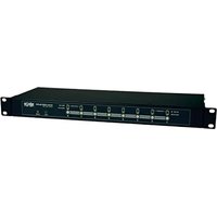


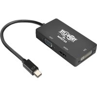
- Owner's Manual
- Monitored Rack PDU Switched Rack PDU
- PDUMNV20HVLX
- PDUMV20HVNET2LX
- PDUMNV30HVLX
- PDUMV30HVNETLX
- PDUMNV32HV2LX
- PROTECT YOUR INVESTMENT!
- Important Safety Instructions
- SAVE THESE INSTRUCTIONS
- Monitored Rack PDU Features
- Switched Rack PDU Features
- Installation
- Mounting the PDU
- Connecting the PDU
- 2-1
- 2-2
- 2-3
- 2-4
- Networking the PDU
- Dynamic IP Address Assignment
- Connection section.
- Static IP Address Assignment / Terminal Menu Configuration Settings
- Testing Network Connection
- Features
- Web Management Card
- Configuration and Operation
- Remote Monitoring and Control
- Service
- Warranty and Product Registration
- LIMITED WARRANTY
- PRODUCT REGISTRATION
- FCC Notice, Class A
- Regulatory Compliance Identification Numbers
- Manual del propietario
- PDUs Monitoreables para Rack PDUs Controlables para Rack
- OU (Vertical) Formato en Barra
- Instrucciones de seguridad importantes 14
- Características de la PDU monitoreada para Rack 14
- Características de la PDU controllable para Rack 15
- Instalación 15
- Configuración y operación 23
- Servicio técnico 23
- Instrucciones de seguridad importantes
- GUARDE ESTAS INSTRUCCIONES
- Características de la PDU Monitoreada para Rack
- Características alternas de la PDU para Rack
- Instalación
- Montaje del PDU
- Conexión del PDU
- Conectando Su PDU a la Red
- Conecte a la Red la Tarjeta para
- Asignación de una Dirección IP Estática / Parámetros de Configuración del Menú de Terminal
- Características
- Adaptador de Clavija de Entrada (Modelos Selectos):
- Interruptores de Circuitos de Salida (Modelos Selectos):
- Soportes para Retención de Cable (Modelos Selectos):
- Tarjeta para Administración de Red
- Configuración y operación
- Control y monitoreo remotol
- Servicio técnico
- Garantía
- Cumplimiento de las normas de los números de identificación
- Manuel du propriétaire
- PDU en bâti surveillée
- Unité de distribution
- d'alimentation (PDU)
- en baie commandée par interrupteur
- Format barrette de connexion OU (Vertical)
- Importantes consignes de sécurité
- CONSERVER CES DIRECTIVES
- Caractéristiques de la PDU en bâti surveillée
- Caractéristiques de la PDU en bâti à liaison commutée
- Montage de l'unité de distribution d'alimentation (PDU)
- 1-1
- 1-2
- 1-3
- 1.4
- Connexion de l'unité de distribution d'alimentation (PDU)
- Mise en réseau de l'unité de distribution
- Affectation d'une adresse IP dynamique
- Affectation d'une adresse IP statique / Paramètres de configuration du menu du terminal
- Test de la connexion réseau
- Caractéristiques
- Adaptateur de fiche d'entrée (certains modèles) :
- Configuration et fonctionnement
- Surveillance et commande à distance
- Entretien
- Garantie
- GARANTIE LIMITÉE
- Numéros d'identification de conformité aux règlements
- Руководство пользователя
- Контролируемый стоечный PDU Управляемый стоечный PDU
- Важные указания по технике безопасности
- СОХРАНИТЕ НАСТОЯЩИЕ УКАЗАНИЯ
- Возможности контролируемых стоечных PDU
- Возможности управляемых стоечных PDU
- Установка
- Монтаж PDU
- Подключение PDU
- (Вариант 1 - только для некоторых моделей.)
- Подключение PDU к сети
- Присваивание динамического IP-адреса
- Присваивание статического IP-адреса / Настройки конфигурации терминального меню
- Проверка сетевого соединения
- 5-1
- Возможности
- Автоматические выключатели (для отдельных моделей):
- Вставки для фиксации разъемов С14 (необязательно):
- Вспомогательное монтажное приспособление
- Карта управления оборудованием через веб-интерфейс
- Порядок настройки и эксплуатации
- Дистанционный контроль и управление
- Сервисное обслуживание
- Гарантийные обязательства
- ОГРАНИЧЕННАЯ ГАРАНТИЯ
- Идентификационные номера, свидетельствующие о соответствии нормативным требованиям
- Benutzerhandbuch
- Überwachte Rack-PDU Geschaltete Rack-PDU
- Wichtige Sicherheitshinweise
- BITTE BEWAHREN SIE DIESE ANLEITUNG AUF
- Überwachte Rack-PDU: Funktionen
- Geschaltete Rack-PDU: Funktionen
- Montage der PDU
- Anschließen der PDU
- Vernetzung der PDU
- Dynamische IP-Adresszuweisung
- Statische IP-Adresszuweisung / Konfigurationseinstellungen für das Terminalmenü
- Netzwerkverbindung testen
- Ausstattung
- Digitales Ladungsmessgerät (Amperemeter): Die
- Konfiguration und Betrieb
- Überwachung und Steuerung aus der Ferne
- Wartung
- BESCHRÄNKTE GARANTIE
- Identifizierungsnummern für ordnungsrechtliche Compliance
Marke : Tripp Lite
Modell : PDUMV20HVNETLX
Kategorie : Rack-Steckdosenleiste