LF611K100MG - Nähmaschine Union Special - Kostenlose Bedienungsanleitung
Finden Sie kostenlos die Bedienungsanleitung des Geräts LF611K100MG Union Special als PDF.

Benutzerfragen zu LF611K100MG Union Special
0 Frage zu diesem Gerät. Beantworten Sie die, die Sie kennen, oder stellen Sie Ihre eigene.
Eine neue Frage zu diesem Gerät stellen
Laden Sie die Anleitung für Ihr Nähmaschine kostenlos im PDF-Format! Finden Sie Ihr Handbuch LF611K100MG - Union Special und nehmen Sie Ihr elektronisches Gerät wieder in die Hand. Auf dieser Seite sind alle Dokumente veröffentlicht, die für die Verwendung Ihres Geräts notwendig sind. LF611K100MG von der Marke Union Special.
BEDIENUNGSANLEITUNG LF611K100MG Union Special
CATALOG NO.
143M
First Edition
STYLES
LF611K100HM
LF611K100MF
LF611K100MG
LF611K100MR
LF611K100MW
LF611K100MAW
LF611K112MF
LF611K112MG
Adjusting instructions and illustrated parts list
natural_image
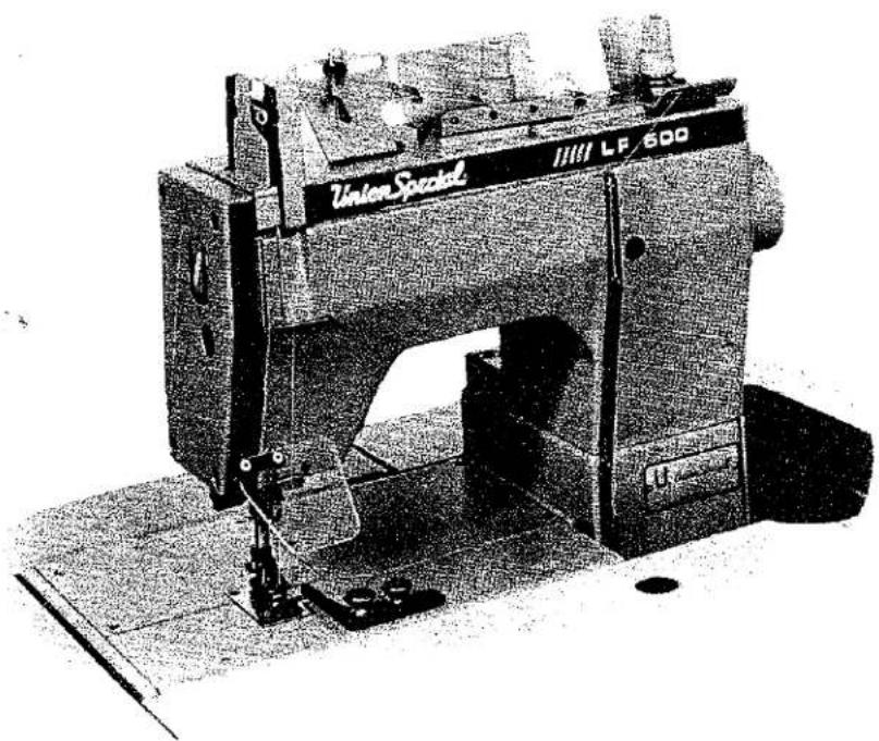
Black-and-white photo of a Union Special sewing machine (no visible text or symbols on the device body)Single-needle, LF600 "Standard Class" plain feed flatbed machines for seaming operations.

natural_image
Pure diagram of a U-shaped pipe or channel with no text, numbers, or symbolsFinest Quality
Union Special®
Industrial Sewing Equipment
FOREWORD
This technical manual has been prepared to guide you in the maintenance of your new UNION SPECIAL machine. Careful attention to the instructions for operating and adjusting these machines will enable you to maintain the superior performance and reliability designed and built into every UNION SPECIAL machine.
The Adjusting Instruction portion of this manual explains in detail the proper setting for each of the components related to forming the stitch and completing the functions of the machine. Figures are used to illustrate the adjustments using reference letters to point out specific items discussed.
Adjustments are presented in sequence so that a logical progression is accomplished. Some adjustments performed out of sequence may have an adverse effect on the function of other related parts.
Implementation of Preventive Maintenance Schedule can bring about significant improvements in operator productivity by avoiding costly equipment breakdowns. Whenever it becomes necessary to make repairs or replace parts on your machine, be sure to insist on genuine UNION SPECIAL Repair Parts. These parts are designed specifically for your machine and manufactured with utmost precision to assure long lasting service.
This Catalog has been made on the basis of available information. Changes in design and/or improvements may incorporate a slight modification of configuration in illustrations or part numbers.
CATALOG NO. 143M
For Styles
LF611K100HM LF611K100MW
LF611K100MF LF611K100MAW
LF611K100MG LF611K112MF
LF611K100MR LF611K112MG
First Edition
Copyright 1987
By
Union Special Corporation
Rights Reserved In All Countries
Printed in U.S.A.
September, 1987
Each UNION SPECIAL machine is identified by a Style number, which on this machine Class, is stamped into the Style plate affixed to the right front of machine. Serial number is stamped into bed casting at the left rear base of machine.
NOTE: Instructions stating direction or location, such as right, left, front or rear of machine, are given relative to the operator's position at the machine, unless otherwise noted. The handwheel rotates counterclockwise in operating direction when viewed from the right end of machine.
STYLES OF MACHINES
High speed, maximum performance, double locked stitch, plain feed flatbed machine. Totally enclosed feed and looper drive mechanism, fully automatic forced feed lubricating system with easily replaceable oil filter, quick stitch change, independently driven rear needle guard and quick adjustable looper avoid.
LF611K100HM Single needle, HIGH sewing capacity machine with sewing parts to accommodate Selvage Edge Binder - for binding mattress ticks made from medium heavy to heavy weight materials. Uses selvage edge binding 5/8, 3/4 and 7/8 inch (15.8, 19.0 and 22.2mm) wide to produce a 5/16, 3/8 and 7/16 inch (7.9, 9.5 and 11.1mm) finish. Standard recommended needle Type 128 GAS, Size 125/049. Stitch range 5-14 S.P.I. Maximum recommended speed 6500 R.P.M.
LF611K100MF Single needle, MEDIUM sewing capacity machine with low inertia presser foot, permitting light presser foot pressure for positive feeding and chaining at high speeds - for long seams on light to medium weight fabrics such as in trousers, skirts, coats, jackets, etc. Standard recommended needle Type 128 GBS, Size 90/036. Stitch range 7-10 S.P.I. Maximum recommended speed 6500 R.P.M., depending on operation.
LF611K100MG Single needle, MEDIUM sewing capacity machine used for side and inseaming men's work and dress pants made from medium weight material. Standard recommended needle Type 128 GBS, Size 90/036. Stitch range 10-14 S.P.I. Maximum recommended speed 6500 R.P.M., depending on operation.
LF611K100MR Same as Style LF611K100MF except - fitted with feeding presser foot with yielding section to left, allowing crossing of seams and pockets.
LF611K100MW Same as Style LF611K100MF except - used for seaming cotton, flannel and leather palm gloves. Standard recommended needle Type 128 GAS, Size 110/044. Stitch range 5-14 S.P.I.
LF611K100MAW Same as Style LF611K100MF except - equipped with narrow feeding presser foot and related sewing parts for 3/16 inch (4.8mm) margin.
LF611K112MF Same as Style LF611K100MF except - equipped with Power "AIR-KLIPP®" chain cutter.
LF611K112MG Same as Style LF611K100MG except - equipped with Power "AIR-KLIPP" chain cutter.
® "AIR-KLIPP" is a registered trademark of Union Special Corporation.
SAFETY RULES

CAUTION!
THIS SYMBOL INDICATES YOUR PERSONAL SAFETY IS INVOLVED
TO PREVENT PERSONAL INJURY:
- All power sources to the machine MUST be TURNED OFF before threading, oiling, adjusting or replacing parts.
- Wear safety glasses.
- All shields and guards MUST be in position before operating machine.
- DO NOT tamper with safety shields, guards, etc., while machine is in operation.
LUBRICATION
IMPORTANT: Machine must be in a leveled position.
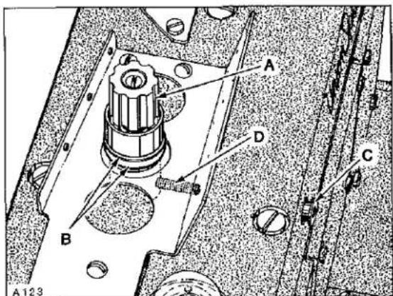
Oil has been drained from main reservoir before shipment. Use a straight mineral oil with a Saybolt viscosity of 90 to 125 seconds at 100 degrees Fahrenheit. This is equivalent to UNION SPECIAL Specification No. 175. Remove oil filler cap (A, Fig. 1) and fill to the TOP line of oil level gauge (B). Replace oil filler cap.
CAUTION! On new machines, machines that have been out of service for an extended period of time OR machines that have been drained of oil and refilled.....RUN MACHINE SLOWLY at 300 R.P.M. for approximately five minutes while paying strict attention to the oil flow indicator which should rise in the oil filler cap (A) and remain steady while machine is running. This must be noted to ensure that oil flow indicator is functioning and oil is circulating. Check oil level while machine is running which MUST be maintained between the red lines of oil level gauge.
To maintain maximum recommended speed and serviceability of these machines, refer to General Preventive Maintenance Schedule. Under no circumstances, should oil remain in the machine for more than one year. Oil drain plug is located in bottom of oil pan. ALWAYS change oil filter when oil is changed. At this time, evaluate the contaminated condition of the oil to determine if the oil filter should be changed more or less frequently. To replace filter, remove four screws (C, Fig. 1) and cover (D); lift out filter cartridge. REMOVE (brass) BY-PASS VALVE FROM TOP OF OLD FILTER AND INSTALL IN NEW FILTER. Reassemble in reverse manner.
LUBRICATION DIAGRAM

text_image
Technical schematic diagram of an electrical device with labeled components A, B, C, and D
PRESSURE OIL

SIPHON RETURN

INLET

FILTER BY-PASS
Fig. 1
text_image
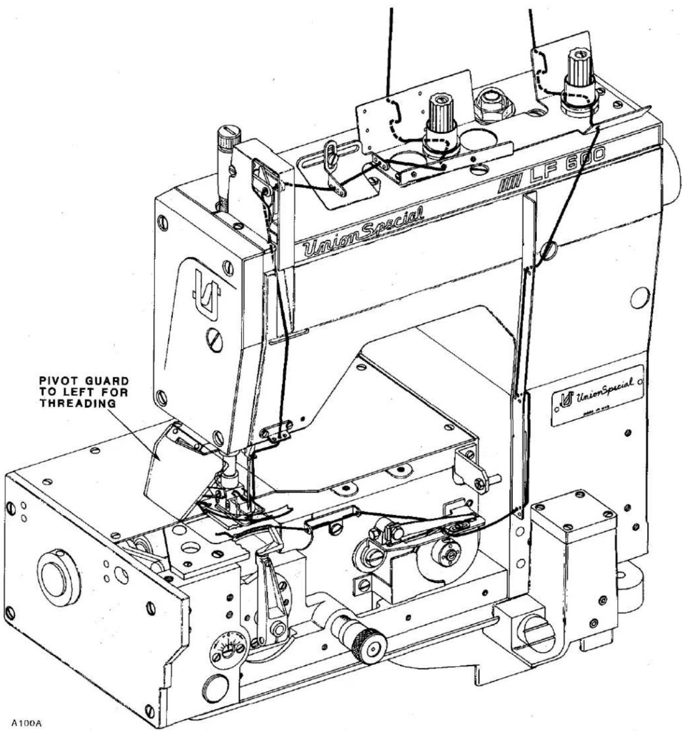
PIVOT GUARD TO LEFT FOR THREADING A100A UnionSpecial UnionSpecial LF600THREADING DIAGRAM
NEEDLES
Each needle has both a type and size number. Type number denotes the kind of shank, point, length, groove, finish and other details. Size number, stamped on the needle shank in metric, denotes largest diameter of blade, measured midway between shank and eye. Collectively, type and size number represent the complete symbol, which is given on the label of all needles packaged and sold by UNION SPECIAL CORPORATION.
The type numbers of the needles recommended for each Style of machine covered by this catalog are given in the machine style description. Other needles are available, but the ones indicated are those recommended to produce the most satisfactory results. The type numbers of the recommended needles together with their descriptions, and the sizes available are listed below:
| NEEDLE TYPE | DESCRIPTION | SIZES AVAILABLE |
| 128 GAS | Round shank, round point, short, double groove, struck groove, ball eye, spotted, chromium plated. | 80/032, 90/036, 100/040, 110/044, 125/049, 140/054, 150/060, 170/067. |
| 128 GBS | Round shank, round point, short, double groove, struck groove, ball eye, spotted, ball point, chromium plated. | 80/032, 90/036, 100/040, 110/044, 125/049, 140/054, 150/060. |
To have needle orders promptly and accurately filled, an empty package, a sample needle, or the type and size number should be forwarded. Use description on label. A complete order would read "1000 needles, Type 128 GBS, Size 90/036".
THREAD MACHINE AS ILLUSTRATED.

text_image
A101 A BFig. 2

text_image
A B A 102 AFig. 3
text_image
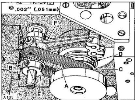
.002" (.051mm) F B A E A103 D CFig. 4
TIMING FEED TO NEEDLE
Adjustment would be required if the machine is feeding while the needle is in the work.
This can be accomplished by removing top cover, head cover, left cloth plate and top feed chamber cover. Rotate handwheel in operating direction to position needle bar at bottom of stroke. At this time, the first screw (A, Fig. 2) in the feed drive eccentric (B) must be on the flat of the feed drive shaft and in a vertical position. Adjustment can be made by loosening two screws (A, Fig. 3) in upper mainshaft sprocket (B). Hold the handwheel firmly with needle bar at bottom of stroke and rotate pulley as required to position screw (A, Fig. 2) so it is vertical. Tighten screws (A, Fig. 3) securely.
SYNCHRONIZING LOOPER AND NEEDLE MOTIONS
NOTE: End cover has been removed for clarity in Figure 4, but MUST BE IN POSITION WHILE MAKING THE FOLLOWING ADJUSTMENTS.
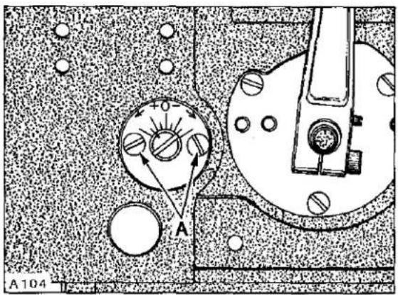
Looper drive belt, (A, Fig. 4) has proper tension if, when turning handwheel in operating direction to position looper in the center of its (right to left) travel...there is no noticeable (right to left) play in the looper mechanism. There should be approximately 1/8 inch (3.2mm) deflection in looper drive belt when pressing firmly with thumb, midway between sprockets (B and C). Adjustment can be made by loosening two screws (A, Fig. 5) and turn looper module (D, Fig. 4) counterclockwise to tighten belt or clockwise to loosen, as viewed in Figure 4. Retighten screws (A, Fig. 5).
To synchronize machine, remove needle bar eyelet guard, needle thread take-up cam, needle, presser foot, throat plate, looper and feed dog. Turn handwheel to position needle bar at BOTTOM of stroke and looper holder at EXTREME right end of travel.
SYCHRONIZING LOOPER AND NEEDLE MOTIONS (Continued)
Using gauge No. 21227 R, mount gauge plate with throat plate attaching screws. Insert pin (included with gauge) into looper holder. Mount indicator block to machine head with one of the screws removed from needle bar eyelet guard. Insert shank of indicator gauge into indicator block and tighten screw against shank. (See sketch A for reference).
Rotate handwheel in OPERATING direction until the pin in looper holder contacts gauge plate. Loosen screw (A, Fig. 6) in needle bar connection (B) and position needle bar (C) as required to set the pointer of indicator gauge at "0" and tighten screw (A) VERY LIGHTLY.
NOTE: This screw is specifically tightened to ONLY 10 in-lbs (11.5 cm/kg).
Rotate handwheel in REVERSE direction until pin in looper holder again makes contact with gauge plate and note the reading on the gauge. A variation of (1) graduation on the scale is permissible. If the reading is above "0", loosen screws (E, Fig. 4) and turn rear looper drive sprocket (B) towards the operator (clockwise as viewed in Figure 4). If the reading is below "0", turn sprocket away from operator (counterclockwise as viewed in Figure 4). Temporarily snug screws.
Rotate handwheel in OPERATING direction until pin in looper holder contacts gauge plate and note the reading on scale. If the reading is above "0", loosen screws (E) and turn sprocket (B) away from operator (counterclockwise as viewed in Figure 4). If the reading is below "0", turn sprocket towards the operator (clockwise as viewed in Figure 4). Temporarily snug screws.
Continue to check and adjust in both OPERATING and REVERSE directions until pointer of indicator gauge comes within (1) graduation on the scale when turning the handwheel in either direction. Before tightening screws (E) securely, be sure to have .002 inch (.051mm) clearance between sprocket (B) and needle guard drive connecting rod (F).
text_image
A A104Fig. 5

natural_image
Technical line drawing of a sewing machine with no visible text or symbolsSKETCH A
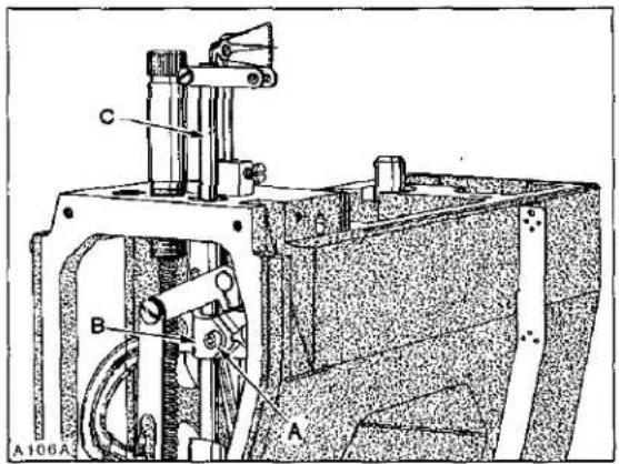
text_image
A106A B C AFig. 6
SYNCHRONIZING LOOPER AND NEEDLE MOTIONS (Continued)
text_image
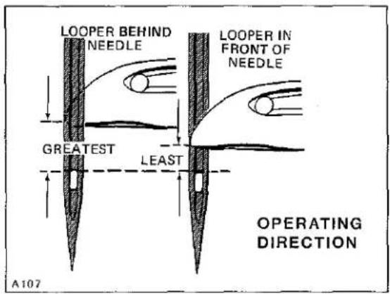
LOOPER BEHIND NEEDLE LOOPER IN FRONT OF NEEDLE GREATEST LEAST A107 OPERATING DIRECTIONSKETCH B
If a synchronizing gauge is not available....turn the handwheel in operating direction to position looper point even with the left side of needle and check the distance from the eye of needle to the bottom of looper blade. Turn handwheel in reverse direction to position looper point even with
the left side of needle and check the distance from the eye of needle to the bottom of looper blade. If the distance was greater when handwheel was turned in operating direction, (as viewed in sketch B) loosen screws (E, Fig. 4) and turn rear looper drive sprocket (B) away from operator (counterclockwise as viewed in Figure 4).
text_image
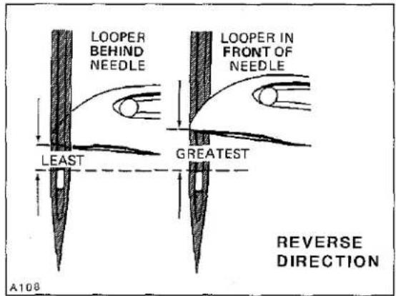
LOOPER BEHIND NEEDLE LEAST GREATEST LOOPER IN FRONT OF NEEDLE A108 REVERSE DIRECTIONSKETCH C
text_image
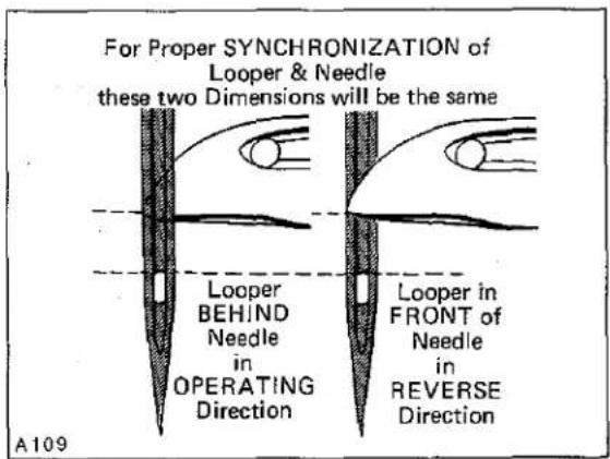
For Proper SYNCHRONIZATION of Looper & Needle these two Dimensions will be the same Looper BEHIND Needle in OPERATING Direction Looper in FRONT of Needle in REVERSE Direction A109SKETCH D
If the distance was greater when handwheel was turned in reverse direction, (as viewed in sketch C) turn sprocket towards the operator (clockwise as viewed in Figure 4). Temporarily snug screws. Continue to check and adjust in both OPERATING and REVERSE directions until the distance from the eye of
the needle to the bottom of looper blade is the same in either direction (as viewed in sketch D). Before tightening screws (E, Fig. 4) securely, be sure to have .002 inch (.051mm) clearance between sprocket (B) and needle guard drive connecting rod (F).

text_image
5/32 inch (4.0mm) A:10 D E C B AFig. 7
LOOPER SETTINGS
Insert a new needle, type and size specified. With looper positioned at EXTREME right end of travel, distance from centerline of needle to point of looper should be 5/32 inch (4.0mm). Adjustment can be made by loosening screw (A, Fig. 7) and turn screw (B) clockwise to increase looper gauge or counterclockwise to decrease. Apply pressure to the upper portion of looper holder (C) to the left while making this adjustment and locking with screw (A). Looper gauge No. 21225-5/32 can be used advantageously while making this adjustment. Looper must also be set so, as it travels to the left behind the needle, NOT to touch, but with a MAXIMUM clearance of .005 inch (.127mm). Adjustment can be made by loosening screw (A) and moving looper holder (C) forward or rearward on its shaft to obtain specified conditions; apply pressure to the upper portion of looper holder to the left while tightening screw (A).
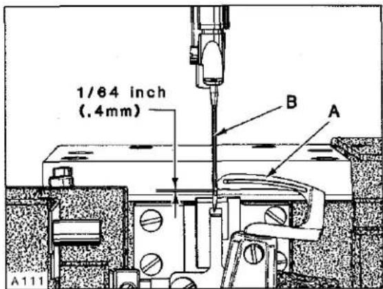
NEEDLE BAR HEIGHT
Turn handwheel in operating direction until POINT of looper (A, Fig. 8) is even with the LEFT side of the needle (B). TOP of needle eye should be 1/64 inch (.4mm) below the undersurface of looper blade, as shown in Figure 8. Adjustment can be made by loosening screw (A, Fig. 9) and move needle bar (B) up or down as required; TORQUE screw (A) to 10 in-lbs (11.5 cm/kg).
text_image
1/64 inch (.4mm) A B A A111Fig. 8
NOTE: Needle bar has a special coating. DO NOT wedge with any type of tool, as damage to same may result.
LOOPER AVOID
Machine is equipped with a quick adjustable looper avoid mechanism to accommodate extreme differences in needle sizes. If looper avoid requires re-setting, loosen two screws (D, Fig. 7) and turn eccentric stud (E) towards the plus side (counterclockwise) for MORE looper avoid or towards the minus side (clockwise) for LESS looper avoid. When desired setting is acquired, tighten screws (D).
NOTE: Whenever looper avoid is changed, always recheck "LOOPER SETTINGS".
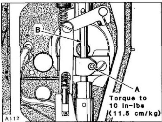
text_image
A B A Torque to 10 In-lbs l(11.5 cm/kg) A112Fig. 9
text_image
A B A119Fig. 10

text_image
A(2) C B E D A 120Fig. 11
text_image
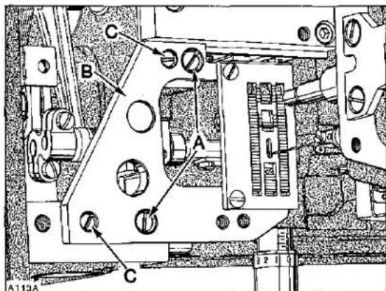
C B A C A113AFig. 12
REAR NEEDLE GUARD TIMING AND ADJUSTMENT
Rotate handwheel in operating direction to position looper point at the RIGHT hand side of needle. At this time the needle guard (A, Fig. 10) should be at its EXTREME END of FORWARD travel. Adjustment can be made by loosening two screws (A, Fig. 11) and turn needle guard eccentric (B) slightly as required until this condition exists. Ensure .002 inch (.051mm) clearance between needle guard eccentric (B) and looper drive sprocket (C) while tightening screws (A) securely. Needle guard should also be positioned (left to right) so the needle centers in the width of the guarding surface. Adjustment can be made by loosening collar screw (D) and pivot link screw (E) permitting guarding surface to be centered to needle. Position collar against needle guard shaft bushing and tighten screw (D) securely. Rotate guard as required to obtain .002-.004 inch (.051-.102mm) clearance between guarding surface and needle. Take up thrust by exerting pressure against collar to the left and pivot link to the right and tighten pivot link screw (E) securely. Guard should be set as low as possible yet have its vertical face approach approximately 3/64 inch (1.2mm) of needle point. Adjustment can be made by loosening two screws (B, Fig. 10) to position guard to proper height and retighten screws (B) securely being sure to keep the width of its guarding surface centered to needle.
NOTE: Change in stitch length WILL NOT require change in needle guard setting, but a change of needle SIZE may.
text_image
A 10 9 8 F D C B A114Fig. 13
FEED DOG SETTINGS
Feed dog should be centered in throat plate with equal clearance on both sides and ends. At highest point of travel, feed dog teeth should extend the depth of a full tooth, or approximately 3/64 inch (1.2mm) above throat plate. MINOR (right to left) adjustments can be made by loosening two screws (A, Fig. 12) in throat plate support (B). Loosen two screws (C) securing two locating ferrules which allow
movement to align throat plate support. Reposition slightly as required, considering both needle hole slot and feed dog slots. Tighten screws (C) first, then screws (A).
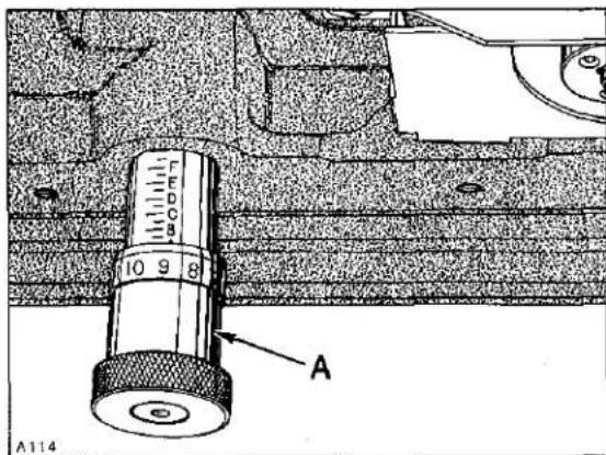
Front to rear adjustment can be made by turning stitch regulating knob (A, Fig. 13) counterclockwise to obtain LONGEST stitch length. Remove rear feed chamber cover which is secured with four screws.
Loosen Allen screw (A, Fig. 14) and turn eccentric (B) while rotating handwheel in operating direction to obtain equal clearance in throat plate, front and rear. Tighten screw (A) securely.
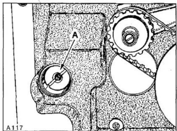
Feed dog can be leveled or tilted by loosening screw (A, Fig. 15) and rotate feed rocker tilting shaft (A, Fig. 16) slightly as required. Check parallelism of feed dog by placing throat plate in position. Before tightening screw (A, Fig. 15), make sure to have approximately .002 inch (.051mm) clearance between feed rocker (B) and spacer sleeve (C).
IMPORTANT: Recheck front to rear clearance of feed dog in throat plate slots whenever feed rocker tilting shaft has been repositioned. Replace rear feed chamber cover.
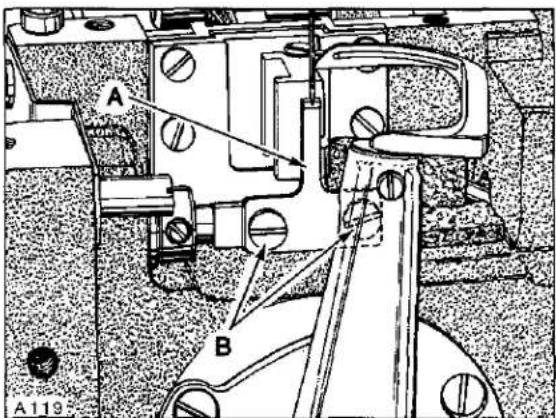
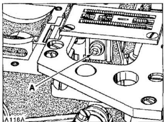
With feed travel set to desired stitch length, set feed dog height as specified by loosening mounting screw (A, Fig. 17) to position as required. Feed dog supporting screw is located in the feed dog holder, adjust as required to support feed dog before tightening screw (A).

text_image
A B A115Fig. 14

text_image
A116 B C AFig. 15
text_image
A A117Fig. 16
natural_image
Technical diagram of a mechanical assembly with labeled components (A, A118A), no readable text or symbols beyond labelsFig. 17

text_image
10 9 8 A A114Fig. 18

text_image
H C A F D 1/16 inch (1.6mm) B 1/32 inch (.8mm) G E A121AFig. 19
text_image
5/8 inch (15.9mm) A B C D Line A122Fig. 20
CHANGING STITCH LENGTH
Stitch length is changed by turning stitch regulating knob (A, Fig. 18) clockwise to shorten the stitch or counterclockwise to lengthen same. Recheck front to rear clearance under "FEED DOG SETTINGS" whenever stitch length is changed. Stop collar at rear of machine attached to stitch regulating knob shaft can be set to prevent stitch length regulating knob (A) from accidentally being turned beyond the desired stitch length.
PRESSER BAR AND PRESSER FOOT (For Styles LF611K100HM, 100MG, 100MW and 112MG)
With needle bar at bottom of stroke and presser foot resting squarely on throat plate, there should be minimum clearance of 1/64 inch (0.4mm) between the bottom of screw (A, Fig. 19) and bottom of slot in presser bar guide plate (B). There should also be 1/16 inch (1.6mm) clearance between bottom of slot in lifter lever link (C) and bottom of presser bar guide (D) when foot lifter lever is released. If adjustment is required, proceed as follows:
Back off presser bar spring regulator to release tension on spring. Loosen two screws (E) in presser bar guide (D). Loosen nut (F) and turn screw (A) down against guide plate (B) to obtain at least 5/64 inch (2.0mm) clearance between bottom of presser bar guide (D) and guide plate (B). Align presser foot with needle and press down FIRMLY while tightening two screws (E) in presser bar guide (D).
NOTE: This setting was necessary to prevent damage to the scraper edge of presser bar bushing, should presser foot be removed from machine. Turn presser bar spring regulator down. Back off screw (A) to obtain the 1/64 inch (0.4mm) dimension between bottom of screw and bottom of slot in presser bar guide plate (B), lock nut (F).
PRESSER BAR AND PRESSER FOOT (Continued) (For Styles LF611K100HM, 100MG, 100MW and 112MG)
Loosen screw (G) in lifter arm (H) and rotate arm slightly as required to obtain the 1/16 inch (1.6mm) dimension between link (C) and guide (D), retighten screw (G) ensuring no left to right shake in lifter arm (H).
Adjust presser bar spring regulator so it exerts only enough pressure on presser foot to feed the work uniformly. Turning it clockwise increases the pressure, counterclockwise acts the reverse.
PRESSER BAR AND PRESSER FOOT (For Styles LF611K100MFand LF611K112MF)
With needle bar at bottom of stroke and presser foot resting on throat plate, there should be 1/32 inch (.8mm) clearance between top of screw and top of slot in presser foot as shown in Figure 19. There should be 1/16 inch (1.6mm) clearance between bottom of slot in lifter lever link (C) and bottom of presser bar guide (D) when foot lifter lever is released. If adjustment is required, proceed as follows: Loosen nut (F) and turn screw (A) down approximately 1/8 inch (3.2mm) below bottom surface of presser bar guide (D). Back off presser spring regulating screw and loosen screws (E) in presser bar guide (D) so that presser foot is sitting squarely on throat plate and screw (A) is touching the bottom of the presser bar guide plate, then secure screws (E).
Turn presser spring regulating screw all the way down, then back off screw (A) counterclockwise to obtain the 1/32 inch (.8mm) dimension in presser foot, lock nut (F). Loosen screw (G) in lifter arm (H) and rotate arm slightly as required to obtain the 1/16 inch (1.6mm) dimension between link (C) and guide (D), retighten screw (G). Make sure that there is no shake, left to right, in lifter arm (H).
FEEDING PRESSER FOOT (For Styles LF611K100MR and LF611K100MAW)
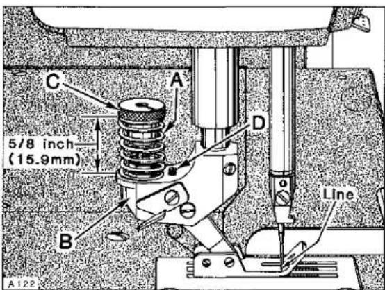
With presser foot resting on throat plate and the needle in its lowest position, the distance from top of spring (A, Fig. 20) to top of yoke (B) should be 5/8 inch (15.9mm) and the line stamped across the presser foot bottom should line up with centerline of needle.
As the presser foot is raised, its bottom should move VERY SLIGHTLY towards the rear...1/64 inch (.4mm) maximum. If adjustment is required, proceed as follows: Remove presser spring regulating screw, presser bar spring guide and presser bar spring. Loosen nut (F, Fig. 19) and turn screw (A) down approximately 1/8 inch (3.2mm) below bottom surface of presser bar guide (D). Loosen screws (E) in presser bar guide (D). Adjust spring regulator nut (C, Fig. 20) as required so its lower surface is 5/8 inch (15.9mm) from top of yoke (B) as viewed in Fig. 20. With presser foot resting on throat plate and feed dog down below throat plate, press down on spring regulator nut (C) until the marks in presser foot bottom align with centerline of needle and positioned to keep needle in center of needle slot. Tighten screws (E, Fig. 19) securing presser bar guide to presser bar, ensuring stop screw (A) in presser bar guide is resting on bottom of presser bar guide plate. Replace presser bar spring, presser bar spring guide and presser spring regulating screw. Turn regulating screw down until the top of its threaded portion is level with head casting. Rotate handwheel to position feed below throat plate with presser foot resting on throat plate. Depress presser foot lifter lever to see if presser foot bottom moves SLIGHTLY towards the rear before presser foot begins to lift.
FEEDING PRESSER FOOT (Continued) (For Styles LF611K100MR and LF611K100MAW)
Adjustment can be made by turning stop screw (D, Fig. 20) clockwise to shorten or counterclockwise to lengthen the distance of travel.
Loosen screw (G, Fig. 19) in lifter arm (H) and rotate arm slightly as required to obtain 1/16 inch (1.6mm) clearance between link (C) and guide (D); retighten screw (G), assuring all end play is removed from lifter arm (H).
Presser foot, at back of needle slot should cover most of throat plate land when resting directly on throat plate.
When the presser foot bottom is raised by material and the feeding foot spring bottoms, rear of needle slot should clear the needle. Main presser bar should not begin to lift before the spring of feeding foot bottoms.
Purpose of the feeding presser foot is to make top and bottom plies of material feed the same amount without pulling on the bottom ply. Final adjustment may be required to match plies; turning nut (C, Fig. 20) to increase pressure on spring (A) will tend to feed the bottom ply more...decreasing pressure will tend to feed the top ply more.
text_image
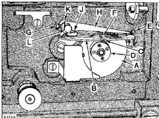
A124A B C D E F G H J K LFig. 21

text_image
A B C A125AFig. 22
LOOPER THREAD TAKE-UP AND CAST-OFF PLATE
Looper thread take-up (A, Fig. 21) must be centered, front to back in cast-off plate (B). It should also be positioned so as the needle bar is descending, the looper thread is "cast-off" the highest lobe of looper thread take-up when the point of the needle is even with the bottom of looper blade.
If adjustment is required, lift cast-off plate up. Loosen screw (A, Fig. 22) in positioning collar (B) and two screws (C) in looper thread take-up. Advance or retard take-up as required. Tighten two screws (C) securely in take-up making sure it is centered in cast-off plate. Positioning collar (B), which has a slot in its face, must be aligned with two screws which secure the discs of take-up together while THRUSTING positioning collar forward against take-up. Remove the play between screw heads in take-up and slot in positioning collar by applying pressure on the collar CLOCKWISE while tightening screw (A) securely. Cast-off plate (B, Fig. 21) should be positioned with .004 inch (0.1mm) clearance between cutting edge of looper thread anti-wrap-up knife (C) and hub (D) of looper thread take-up, which can be adjusted by repositioning latch (E). Set adjustable eyelets (F) in the center of their mounting screws. More or less, looper thread can be supplied in the stitch by moving adjustable eyelets to the right or left respectively.
LOOPER THREAD TAKE-UP AND CAST-OFF PLATE (Continued)
If retaining finger is rubbing take-up, loosen screw (G), center the finger (H) and retighten screw. If retaining finger is on an angle, loosen screw (J), turn retaining finger support (K) slightly as required and retighten screw. The height of retaining finger can be adjusted by loosening screw (L), set to required height and tighten screw securely.
THREAD TENSION RELEASE
Needle thread tension assembly (A, Fig. 23) is set correctly when the tension discs (B) start to release as the presser foot is raised to within 1/8 inch (3.2mm) of the end of its travel and completely released when presser foot has reached its highest position.
Adjustment can be made by removing plastic plug (C) and loosening screw (D) and lower the tension assembly (A) to advance the release action or raise tension assembly to retard the release action. Hold tension assembly in position while retightening screw (D). Reassemble plastic plug securely.
text_image
A B D C A 123Fig. 23
THREAD CONTROL (PRELIMINARY SETTINGS)
Needle bar eyelet (A, Fig. 24) should be set with its eyelets 1/16 inch (1.6mm) below strike-off (B) on needle thread cam (C), as shown in Figure 24, with needle bar at BOTTOM of stroke.
Adjustments can be made by bringing needle bar up, loosen screw (D) slightly, bring needle bar down to BOTTOM of stroke, reposition eyelet (A) as required and bring needle bar back up. Torque screw (D) to 10 in-lbs (11.5 cm/kg).

text_image
D C 1/16" (1.6mm) A B E A127Fig. 24
Needle thread cam (C) should be set to barely contact needle thread with needle bar at top of stroke. Adjustment can be made by loosening needle thread cam attaching screw (E), reposition cam forward or rearward as required and retighten screw (E).
THREAD CONTROL (PRELIMINARY SETTINGS) (Continued)

text_image
1 7/8 inch (47.6mm) 1 5/16 inch (33.3mm) STANDARD EYELET POSITION A126 EYELET POSITION FOR LOOSE STITCH Union Special.As a starting point, the needle thread (adjustable) eyelet should be set 1 7/8 inch (47.6mm) from its right side to the right side of the thread control plate eyelet and 1 5/16 inch (33.3mm) from centerline of its eyelet to the top of the top cover, as illustrated above.
Tension on needle thread should be just enough to pull up uniform stitches. Tension on looper thread should be just enough to steady thread.

text_image
H G K C B A J D E F 1/32" (.8mm) A128Fig. 25
POWER "AIR-KLIPP" CHAIN CUTTER ADJUSTMENTS
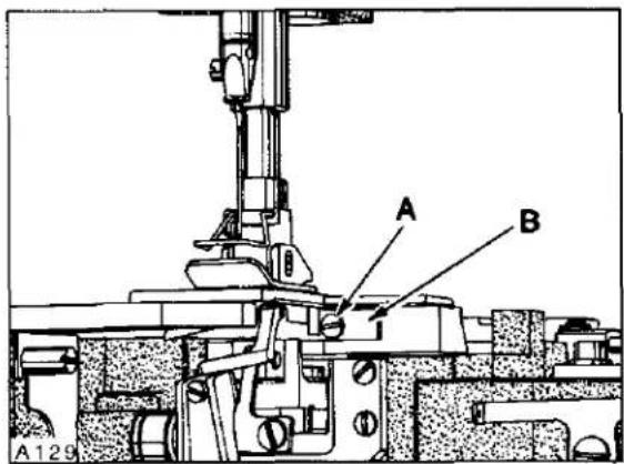
Upper knife (A, Fig. 25) can be replaced by removing two screws (B). To replace lower knife, the upper knife must be removed and rear suction tube cover. Loosen two screws (C) and slide housing (D) towards the rear. Remove screw (A, Fig. 26) and lift up thread inlet (B). Unhook knife spring (E, Fig. 25) and remove lower knife (F). Reassemble knives in reverse manner. Reassemble thread inlet (B, Fig. 26) and slide housing (D, Fig. 25) forward against rear of throat plate; tighten two screws (C).
SETTING KNIFE CROSS OVER
Adjustment may be necessary after replacing or repairing knives. With sewing motor switch in "OFF" position and air lines connected to air motor, depress treadle until air motor begins to operate, in and out.
POWER "AIR-KLIPP" CHAIN CUTTER ADJUSTMENTS (Continued)
IMPORTANT:
Be sure that lower knife does NOT strike against knife housing or feed chamber cover. Adjustment should be accomplished by loosening two screws (G, Fig. 25) and reposition air motor (H) left or right slightly, but under extreme circumstances it may become necessary to shorten the stroke of lower knife travel by repositioning coupling (J).
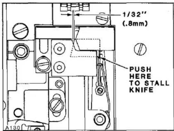
Carefully press against lower knife (F, Fig. 25) until air motor stalls. With treadle still depressed, check the knife cross over. Cross over of lower knife to upper knife is positioned correctly when the lower knife is 1/32 inch (.8mm) from the front of upper knife as shown in Figure 25. If adjustment is required, loosen screw (K) and reposition coupling (J) as required to obtain specified dimension.
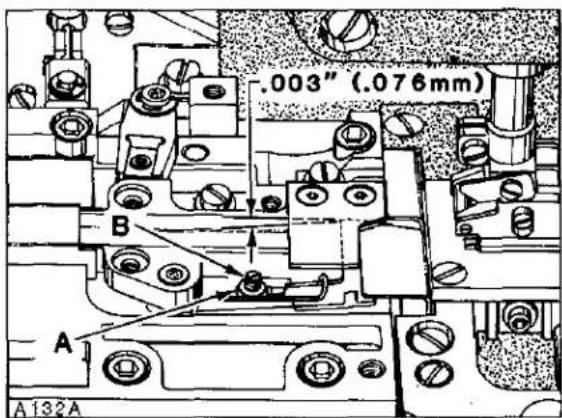
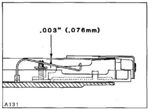
SHEAR ANGLE
Shear angle should be .003 inch (.076mm), measured at rear cutting edge of lower knife (F, Fig. 25) and cutting edge of upper knife (A). Adjustment can be made by loosening nut (A, Fig. 27) and turning screw (B) clockwise to increase the angle or counterclockwise to decrease. Lock nut (A) after shear angle is set.
SETTING PRESSURE VALVES
Regulate valve on pneumatic control device for air motor of the "AIR-KLIPP" chain cutter to approximately 20-22 p.s.i. (1.5 bar) when air motor is operating. Regulate valve on pneumatic control device for the suction air to obtain maximum suction, yet so that the FABRIC TO BE SEWN will not be cut by the "AIR-KLIPP" chain cutter knives.
text_image
A B A129Fig. 26
text_image
1/32" (.8mm) PUSH HERE TO STALL KNIFE A130KNIFE CROSS OVER
text_image
.003" (.076mm) B A A132AFig. 27
text_image
.003" (.076mm) A131SHEAR ANGLE
GENERAL PREVENTIVE MAINTENANCE SCHEDULE
| LF 600 TASK | DAILY | AFTER FIRST MONTH | EVERY MONTH | EVERY-3-MONTHS | EVERY-6-MONTHS | Yearly |
| Check oil level (sight gauge)oil level between red lines. | LF600 | |||||
| Check pump operation (oil flow indicator-top of arm) | LF600 | |||||
| Clean lint and dirt from machine | LF600 | |||||
| Check that all guards and shields are in place and being used | LF600 | |||||
| Change oil-filter (housed-on machine bottom cover) | LF600 | LF600 | ||||
| Change oil (oil which conforms to U.S.C.spec 175 must be used) | LF600 | LF600 | ||||
| Clean lint and dirt from suction screen (inside bottom cover) | LF600 | |||||
| Clean head oil suction screen | LF600 | |||||
| Check tension on internal timing belts | LF600 | LF600 | ||||
| Inspect clutch/positioner motor, V-belt, tension and wear | LF600 | |||||
| Check clutch motor clutch/brake adjustment | LF600 | |||||
| Clean lint from clutch/positioner motor air passages | LF600 | LF600 | ||||
| Check needle (S) bent, blunt, sharp or worn eye or groove | LF600 |
NOTE: SCHEDULING IS BASED ON NORMAL WORKING CONDITIONS FREQUENCY OF TASKS DEPENDS ON MACHINE DUTY CYCLE TIME AND PERSONNEL RESPONSIBLE TO PERFORM TASK DETERMINED BY PLANT MANAGEMENT.
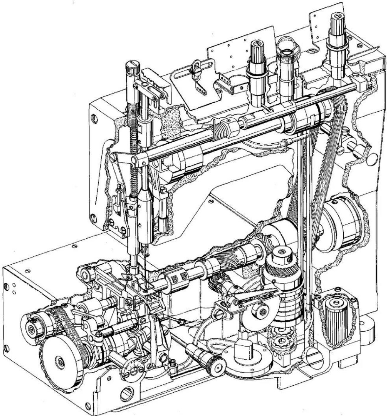
natural_image
Technical line drawing of a mechanical assembly with gears, springs, and housing (no text or labels)EXPLODED VIEWS
AND
DESCRIPTION OF PARTS
P101

text_image
TORQUE TO 30 in. Tbs. (35 cm/kg)-1

text_image
TORQUE TO 16-18 in. 1bs. (18-21 cm/kg) TORQUE TO 16-18 in. 1bs. (18-21 cm/kg)P102
OIL PUMP, PAN, AND LUBRICATING PARTS
| Ref.No. | PartNo. | Description | Amt.Req. |
| 1 | 50393 E | Pump Assembly, oil ---- | 1 |
| 2 | 22653 B-36 | Screw ---- | 4 |
| 3 | 50393 F | Housing, (pressure side) ---- | 1 |
| 4 | C50093 U | Gerotor, 1/4 inch (6.4mm) thick ---- | 1 |
| 5 | C50093 T | Divider, housing ---- | 1 |
| 6 | 660-684 | "0" Ring ---- | 1 |
| 7 | C50093 S | Spacer, housing ---- | 1 |
| 8 | C50093 R | Gerotor, 1/8 inch (3.2mm) thick ---- | 1 |
| 9 | 50393 J | Housing, (syphon side) ---- | 1 |
| 10 | 35036 X | Collar, (positioning and thrust) ---- | 1 |
| 11 | 22894 C | Screw ---- | 2 |
| 12 | C50093 Z | Pin, dowel ---- | 1 |
| 13 | 50393 D | Shaft, drive ---- | 1 |
| 14 | 89 | Screw ---- | 1 |
| 15 | 50393 C | Bushing, oil delivery ---- | 1 |
| 16 | 50393 V | Retainer, wire ---- | 1 |
| 17 | 50393 AX | Tube, oil return ---- | 1 |
| 18 | 50393 BB | Restrictor, oil ---- | 2 |
| 19 | 50393 AT | Cap, oil indicator ---- | 1 |
| 20 | 50393 A | Indicator, oil, (priority metering valve) ---- | 1 |
| 21 | 50394 K | Connector, oil, single feed ---- | 1 |
| 22 | C50094 C | Connector, oil, single feed ---- | 4 |
| 23 | 35094 A | Screw, oil connection ---- | 2 |
| 24 | 668-885 | Clamp, oil tube ---- | 2 |
| 25 | 22841 M | Stand, oil plug ---- | 1 |
| 26 | 35039 A | Gear, driven, oil pump ---- | 1 |
| 27 | 22894 J | Screw ---- | 2 |
| 28 | 661-51 | "0" Ring, ---- | 1 |
| 29 | 660-455 | "0" Ring, ---- | 1 |
| 30 | 74 E | Screw ---- | 1 |
| 31 | 22586 | Screw, locking ---- | 1 |
| 32 | 22541 | Screw ---- | 4 |
| 33 | C50093 F | Cover, oil filter ---- | 1 |
| 34 | C50093 G | Gasket ---- | 1 |
| 35 | C50093 CB | By-Pass, oil filter ---- | 1 |
| 36 | C50093 CA | Filter, oil ---- | 1 |
| 37 | 660-206 | "0" Ring ---- | 1 |
| 38 | 999-211 E | "0" Ring ---- | 2 |
| 39 | 50393 BA | Bracket, manifold ---- | 1 |
| 40 | 50393 AW | Syphon Assembly, oil ---- | 1 |
| 41 | 50393 AU | Screen, oil ---- | 1 |
| 42 | 79-31 | Ball, steel ---- | 1 |
| 43 | 50393 AV | Manifold, oil syphon ---- | 1 |
| 44 | 671 F-41 | Fitting ---- | 1 |
| 45 | C50093 CJ | Tube, oil return ---- | 1 |
| 46 | 50393 AY | Tube, oil ---- | 1 |
| 47 | C50094 R | Tube, oil ---- | 1 |
| 48 | 258 | Nut ---- | 1 |
| 49 | 50393 BK | Fitting, oil ---- | 1 |
| 50 | 50394 B | Tube, oil ---- | 3 |
| 51 | 50394 L | Tube, oil, complete (take-up gear) ---- | 1 |
| 52 | 50393 X | Screen, filter ---- | 1 |
| 53 | 666-310 | Felt, oil return ---- | 1 |
| 54 | C50094 B | Connector, double feed ---- | 1 |
| 55 | 50394 G | Tube, oil (looper rocker) ---- | 1 |
| 56 | WO-3 | Yarn, Columbia, rear needle guard bushing (8 strands) ---- | 1 |
| 57 | C50094 AK | Plug, felt, oil return ---- | 1 |
| 58 | 22720 A | Screw, oil connection ---- | 1 |
| 59 | 22652 A-4 | Screw ---- | 1 |
| 60 | 50393 AR | Clamp, oil screen housing ---- | 1 |
| 61 | C50094 Y | Tube, oil ---- | 1 |
| 62 | 670 E-2 | Tie, cable, to secure Ref. No. 45 to Ref. No. 22 ---- | 1 |
| 63 | 35093 F | Housing, screen ---- | 1 |
| 64 | 35093 H | Screen ---- | 1 |
| 65 | 35093 J | Plate, retaining ---- | 1 |
| 66 | 97 | Screw ---- | 3 |
| 67 | 35082 B | Gasket, oil pan ---- | 1 |
| 68 | 6042 A | Washer ---- | 7 |
| 69 | 820 | Screw ---- | 7 |
| 70 | 50393 N | Pan, oil ---- | 1 |
| 71 | 22571 E | Screw, oil drain plug ---- | 1 |
| 72 | 22571 J | Screw, plug ---- | 2 |

text_image
TORQUE TO 19-21 in. 1bs. (22-24 cm/kg) P103 NOTE Ref. Nos. 30 & 31 on page 23 secure 011 Pump AssemblyMAIN FRAME BUSHINGS AND PLUGS
| Ref.No. | PartNo. | Description | Amt.Req. |
| 1 | 136 A | Screw ---- | 2 |
| 2 | 50344 K | Bushing, lower mainshaft ---- | 1 |
| 3 | 660-739 | Seal, oil presser bar bushing ---- | 1 |
| 4 | C50057 D | Bushing, presser bar ---- | 1 |
| 5 | C067 B | Plug, cork ---- | 2 |
| 6 | C50093 CT | Plug, oil ---- | 3 |
| 7 | C50093 AY | Plug, oil ---- | 3 |
| 8 | 50354 C | Bushing, needle bar (upper) ---- | 1 |
| 9 | 51-794 BLK. | Plug, aluminum ---- | 1 |
| 10 | 22539 G | Screw, plug ---- | 1 |
| 11 | 666-311 | Screen, needle bar bushing ---- | 1 |
| 12 | C50054 D | Shield, needle bar bushing ---- | 1 |
| 13 | C50093 AX | Plug, oil ---- | 1 |
| 14 | 604 | Screw, plug ---- | 2 |
| 15 | 22586 | Screw, locking ---- | 5 |
| 16 | 74 E | Screw, plug ---- | 4 |
| 17 | 50394 S | Plug, steel ---- | 1 |
| 18 | 22533 A | Screw, plug ---- | 1 |
| 19 | 22764 C | Screw, set ---- | 1 |
| 20 | 50390 C | Bushing, presser foot lifter lever (right) ---- | 1 |
| 21 | 50390 | Bushing, presser foot lifter lever (rear) ---- | 1 |
| 22 | C50055 H | Screw, set ---- | 1 |
| 23 | 22706 C | Screw, locking ---- | 1 |
| 24 | 50390 A | Bushing, presser foot lifter lever (front) ---- | 1 |
| 25 | 51-627 BLK. | Plug ---- | 1 |
| 26 | 22565 | Screw, plug ---- | 1 |
| 27 | C50093 CN | Plug, aluminum ---- | 1 |
| 28 | C50035 Z | Plug, oil ---- | 1 |
| 29 | 50390 D | Bushing, presser foot lifter lever (left) ---- | 1 |
| 30 | 50355 L | Bushing, upper mainshaft ---- | 1 |
| 31 | 50354 B | Bushing, needle bar (lower) ---- | 1 |
| 32 | 22894 C | Screw, plug ---- | 3 |
| 33 | 50344 L | Bushing, lower mainshaft ---- | 1 |
| 34 | 50344 G | Bushing, take-up shaft (front) ---- | 1 |
| 35 | 50344 F | Bushing, take-up shaft (rear) ---- | 1 |
| 36 | 50344 B | Bushing, lower mainshaft ---- | 1 |
| 37 | 50368 B | Bushing, rear needle guard shaft ---- | 1 |
| 38 | 50344 E | Bushing, looper rocker (rear) ---- | 1 |
| 39 | 35036 AB | Bushing, stitch control shaft ---- | 1 |

text_image
Technical diagram of a mechanical assembly with numbered components and exploded viewsSAFETY SHIELD, COVERS AND PLATES
| Ref. No. | Part No. | Description | Amt. Req. |
| 1 | C50095 G | Shield Assembly, safety | 1 |
| 2 | 12934 A | Nut | 2 |
| 3 | RM2879-2 | Rivet | 2 |
| 4 | 97127 | Washer, spring | 2 |
| 5 | C50095 F | Shield, safety | 1 |
| 6 | C50095 E | Bracket, mounting | 1 |
| 7 | C50095 D | Stud | 1 |
| 8 | C50082 R | Cover, head | 1 |
| 9 | 660-219 A | Pin, roll (stop) | 1 |
| 10 | C50082 AA | Gasket | 1 |
| 11 | 22883 B | Screw, plug | 1 |
| 12 | 22541 C | Screw | 4 |
| 13 | C50082 AW | Gasket | 1 |
| 14 | C50082 K | Gasket | 1 |
| 15 | C50082 V | Cover, head (left rear) | 1 |
| 16 | 22569 M | Screw | 9 |
| 17 | C50082 M | Cover, head (right rear) | 1 |
| 18 | C50082 N | Gasket | 1 |
| 19 | 22861 C | Screw | 4 |
| 20 | 50382 G | Cover, top | 1 |
| 21 | 22894 J | Screw | 2 |
| 22 | 50394 J | Plug, oil | 2 |
| 23 | C50093 AU | Cap, oil filler | 1 |
| 24 | C50082 X | Gasket | 1 |
| 25 | 50382 F | Gasket | 1 |
| 26 | 22526 H | Screw | 10 |
| 27 | 50382 J | Cover | 1 |
| 28 | 22525 E | Screw | 9 |
| 29 | 22841 N | Screw, adaptor | 1 |
| 30 | 50382 H | Cover | 1 |
| 31 | 87 | Screw, all Styles except LF611K100HM and 100MW | 2 |
| 31A | 22570 | Screw, for Styles LF611K100HM and 100MW | 2 |
| 32 | -- - | Throat Plate, See "SEWING COMBINATIONS" | 1 |
| 33 | 22839 | Screw | 2 |
| 34 | 35036 AE | Ferrule, locating | 2 |
| 35 | 22587 N | Screw | 2 |
| 36 | 50380 | Support, throat plate, all Styles except LF611K100HM and 100MW | 1 |
| 36A | 50380 D | Support, throat plate, for Styles LF611K100HM and 100MW | 1 |
| 37 | 660-939 | Bumper, rubber | 1 |
| 37A | 51280 K | Pin, dowel | 2 |
| 38 | 22799 AH | Stud, latch spring | 1 |
| 39 | 50393 U | Shield, lint | 1 |
| 40 | 94 | Screw | 1 |
| 41 | 22517 | Screw | 4 |
| 42 | 999-216 C | Plug, plastic | 1 |
| 43 | 50382 A | Cover, end | 1 |
| 44 | 22894 D | Screw (bearing) | 2 |
| 45 | 35082 F | Gasket | 1 |
| 46 | 35082 E | Cover, feed chamber (rear) | 1 |
| 47 | 22569 D | Screw | 4 |
| 48 | 50301 B | Support, cloth plate, all Styles except LF611K112MF and 112MG | 2 |
| - | 50301 B | Support, cloth plate, for Styles LF611K112MF and 112MG | 1 |
| 49 | 93 | Screw, all Styles except LF611K112MF and 112MG | 4 |
| - | 93 | Screw, for Styles LF611K112MF and 112MG | 2 |
| 50 | 50382 D | Gasket | 1 |
| 51 | 50382 E | Cover, feed chamber (top) for Styles LF611K100MF, 100MG, 100MR and 100MAW | 1 |
| - | 50382 EA | Cover, feed chamber (top) for Styles LF611K100HM and 100MW | 1 |
| 52 | 22653 B-8 | Screw | 6 |
| 53 | 50301 A | Plate, cloth (left) for Styles LF611K100MF, 100MG, 100MR and 100MAW | 1 |
| - | 50301 R | Plate, cloth (left) for Styles LF611K100HM and 100MW | 1 |
| 54 | 50301 | Plate, cloth (right) | 1 |

text_image
TORQUE TO 10-12 in. 1bs. (12-14 cm/kg) TORQUE TO 16-18 in. 1bs. (18-21 cm/kg) TORQUE TO 10-12 in. 1bs. (12-14 cm/kg) TORQUE TO 6 in. 1bs. (7 cm/kg) P105
text_image
P106 TORQUE TO 28 in. 1bs. (32 cm/kg) TORQUE TO 36 in. 1bs. (41 cm/kg)LOWER MAINSHAFT, LOOPER AND REAR NEEDLE GUARD DRIVE
| Ref.No. | PartNo. | Description | Amt.Req. |
| 1 | 660-220 | "0" Ring ---- | 1 |
| 2 | 50322 AA | Mainshaft, lower (right) ---- | 1 |
| 3 | 35021 | Pulley ---- | 1 |
| 4 | 22650 CD-6 | Screw, set ---- | 2 |
| 5 | 35021 B | Guard, pulley ---- | 1 |
| 6 | 22894 C | Screw, set ---- | 2 |
| 7 | 50342 H | Sprocket, lower mainshaft (right) ---- | 1 |
| 8 | 22894 X | Screw ---- | 2 |
| 9 | 660-212 | "0" Ring ---- | 1 |
| 10 | 660-935 | "0" Ring ---- | 1 |
| 11 | 50343 | Coupling, lower mainshaft ---- | 1 |
| 12 | 22652 A-8 | Screw ---- | 2 |
| 13 | 22894 AE | Screw, set ---- | 2 |
| 14 | 50393 S | Housing, lower mainshaft ---- | 1 |
| 15 | 660-998 | Seal,oil ---- | 1 |
| 16 | 35055 V | Washer, thrust ---- | 1 |
| 17 | 25 S | Screw, retaining (lower mainshaft housing) ---- | 2 |
| 18 | 35055 V | Washer (spacer) ---- | 1 |
| 19 | 62245 C | Stud, locating ---- | 1 |
| 20 | 50339 | Gear, oil pump drive (nylon) ---- | 1 |
| 21 | 22894 AD | Screw, set ---- | 1 |
| 22 | 22894 K | Screw, spot ---- | 1 |
| 23 | 50342 D | Gear, take-up drive ---- | 1 |
| 24 | 22894 C | Screw ---- | 2 |
| 25 | 50393 AN | Pump Assembly, oil siphon ---- | 1 |
| 26 | 660-885 | Clamp, tube ---- | 1 |
| 27 | 50393 AL | Tube, brass ---- | 1 |
| 28 | 666-214 | Felt ---- | 1 |
| 29 | 57847 | Collar ---- | 1 |
| 30 | 95 | Screw ---- | 2 |
| 31 | C50042 AD | Belt, looper drive ---- | 1 |
| 32 | 50368 C | Connecting Rod, needle guard ---- | 1 |
| 33 | 22830 | Screw ---- | 1 |
| 34 | 22894 AD | Screw ---- | 2 |
| 35 | 660-934 | Seal, oil ---- | 1 |
| 36 | C50068 AR | Shaft, rear needle guard ---- | 1 |
| 37 | 50368 A | Pin, pivot ---- | 1 |
| 38 | 50368 E | Washer, non-metallic ---- | 1 |
| 39 | 22743 | Screw, for 50368 D ---- | 1 |
| 40 | 50368 D | Collar, thrust ---- | 1 |
| 41 | 6042 A | Washer ---- | 1 |
| 42 | 50368 | Connection, rear needle guard pivot ---- | 1 |
| 43 | 22729 | Screw ---- | 2 |
| 44 | 29105 AT | Drive Assembly, looper ---- | 1 |
| 45 | 667 J-33 | Pin, crank ---- | 1 |
| 46 | 22653 J-8 | Screw ---- | 1 |
| 47 | 50342 B | Sprocket, looper drive ---- | 1 |
| 48 | 22894 AD | Screw ---- | 2 |
| 49 | 50342 A | Sprocket, looper driven ---- | 1 |
| 50 | 22894 AD | Screw ---- | 2 |
| 51 | 660-979 | "0" Ring ---- | 1 |
| 52 | 660-206 | "0" Ring ---- | 1 |
| 53 | 50314 | Eccentric, looper avoid adjusting ---- | 1 |
| 54 | 50314 A | Plate, eccentric retaining ---- | 1 |
| 55 | 22569 G | Screw ---- | 2 |
| 56 | 29192 AE | Rocker Assembly, looper ---- | 1 |
| 57 | 660-455 | "0" Ring ---- | 1 |
| 58 | 50344 C | Housing, looper rocker bearing ---- | 1 |
| 59 | C50044 V | Seal,oil ---- | 1 |
| 60 | 50313 | Holder, looper ---- | 1 |
| 61 | 22652 B-10 | Screw, binder ---- | 1 |
| 62 | 22575 B | Screw, adjusting ---- | 1 |
| 63 | 22565 X | Screw, set ---- | 1 |
| 64 | 21210 | Collar, looper, for Styles LF611K100HM and 100MW ONLY ---- | 1 |
| 65 | G51409 C | Looper, all Styles except LF611K100HM and 100MW ---- | 1 |
| - | 51909 C | Looper, for Style LF611K100HM ---- | 1 |
| - | 51208 | Looper, for Style LF611K100MW ---- | 1 |
| 66 | 22569 G | Screw ---- | 3 |
| 67 | 90 | Screw ---- | 2 |
| 68 | 50325 | Guard, needle ---- | 1 |
text_image
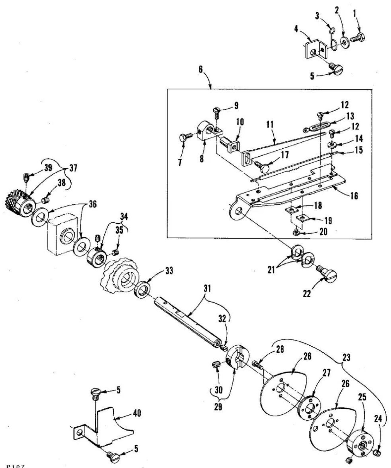
Technical diagram of a mechanical assembly with numbered components and exploded views, likely from an engineering or patenting context.P107
LOOPER THREAD CAST-OFF AND DRIVING PARTS
| Ref.No. | PartNo. | Description | Amt.Req. |
| 1 | 22781 | Screw | 1 |
| 2 | 53678 N | Washer | 1 |
| 3 | 50332 | Spring, latch | 1 |
| 4 | 50357 A | Bracket, mounting | 1 |
| 5 | 22569 D | Screw | 3 |
| 6 | 50357 B | Plate Assembly, cast-off support | 1 |
| 7 | 22588 S | Screw | 1 |
| 8 | 52904 E | Bracket, retaining finger support | 1 |
| 9 | 22768 | Screw | 1 |
| 10 | 52804 E | Support, retaining finger | 1 |
| 11 | 50304 A | Finger, retaining | 1 |
| 12 | 73 A | Screw | 4 |
| 13 | 52958 D | Eyelet | 2 |
| 14 | 157-15 | Washer | 2 |
| 15 | 50323 D | Strike-off | 1 |
| 16 | 50357 | Plate, cast-off support | 1 |
| 17 | 22588 A | Screw | 1 |
| 18 | 50357 G | Knife, anti-wrap up (back) | 1 |
| 19 | 50357 H | Knife, anti-wrap up (front) | 1 |
| 20 | 22798 | Screw | 2 |
| 21 | 99521 | Washer, spring | 2 |
| 22 | 50357 D | Screw, shoulder | 1 |
| 23 | 50323 | Take-Up Assembly, looper thread | 1 |
| 24 | 22894 C | Screw | 2 |
| 25 | 50323 B | Hub | 1 |
| 26 | 50323 A | Disc, take-up | 2 |
| 27 | C50077 P | Spacer | 1 |
| 28 | 22797 B | Screw | 2 |
| 29 | 50323 C | Collar, positioning | 1 |
| 30 | 22894 C | Screw | 1 |
| 31 | 50342 F | Shaft, take-up | 1 |
| 32 | 89 | Screw | 1 |
| 33 | 660-986 | Seal, lip | 1 |
| 34 | 50344 H | Collar, thrust | 1 |
| 35 | 22894 C | Screw | 2 |
| 36 | 54274 P | Washer, thrust | 2 |
| 37 | 50342 E | Gear, take-up (driven) | 1 |
| 38 | 22894 C | Screw, set | 1 |
| 39 | 22894 D | Screw, spot | 1 |
| 40 | 50357 F | Guard, take-up disc | 1 |

text_image
Technical diagram of a mechanical assembly with numbered components for identification and assembly reference.P108
FEED DRIVE AND STITCH REGULATING PARTS
| Ref. No. | Part No. | Description | Amt. Req. |
| 1 | 50322 K | Mainshaft, lower (left) ---- | 1 |
| 2 | 22591 | Screw ---- | 1 |
| 3 | 50335 L | Collar, feed bar thrust ---- | 1 |
| 4 | 22894 C | Screw, set ---- | 2 |
| 5 | 999-211 C | "0" Ring ---- | 1 |
| 6 | 22591 A | Screw, set ---- | 2 |
| 7 | 35034 N | Shaft, rocker ---- | 1 |
| 8 | 50336 C | Spacer, rocker shaft ---- | 1 |
| 9 | 50334 K | Rocker, feed ---- | 1 |
| 10 | 22596 E | Screw ---- | 1 |
| 11 | 22571 D | Screw, plug ---- | 1 |
| 12 | 35034 M | Bushing, rocker shaft ---- | 1 |
| 13 | 35040 B-15 | Eccentric, double, all Styles except LF611K100HM ---- | 1 |
| - | 35040 B-22 | Eccentric, double, for Style LF611K100HM ---- | 1 |
| 14 | 22894 J | Screw ---- | 2 |
| 15 | 29126 FB | Fork Assembly, driving ---- | 1 |
| 16 | 35034 J | Stud, eccentric ---- | 1 |
| 17 | 29126 EV | Feed Bar Assembly ---- | 1 |
| 18 | 35036 AZ | Pad, brake ---- | 1 |
| 19 | 35036 F | Bushing, stitch adjusting shaft ---- | 1 |
| 20 | 661-50 | Washer, cup ---- | 1 |
| 21 | 22894 AB | Screw ---- | 2 |
| 22 | 35036 C | Shaft Assembly, stitch adjusting ---- | 1 |
| 23 | 50335 | Retainer, spring ---- | 1 |
| 24 | 22714 C | Screw, tension (feed adjusting) ---- | 1 |
| 25 | 50355 | Spring ---- | 1 |
| 26 | 50335 A | Holder, spring ---- | 1 |
| 27 | 50336 D | Lever, stitch control ---- | 1 |
| 28 | 22596 E | Screw ---- | 2 |
| 29 | 661-35 | Pin ---- | 1 |
| 30 | 50335 C | Cam, roller ---- | 1 |
| 31 | 77 K | Screw ---- | 1 |
| 32 | 50335 E | Shaft, stitch control ---- | 1 |
| 33 | 660-206 | "0" Ring ---- | 1 |
| 34 | 35036 AP | Knob, stitch adjusting shaft ---- | 1 |
| 35 | 22764 A | Screw ---- | 1 |
| 36 | 22617 J-16 | Screw ---- | 10 |
| 37 | 50334 B | Guide, feed bar (front) ---- | 1 |
| 38 | 50334 AB | Seal, feed bar, (front) ---- | 1 |
| 39 | 50334 C | Guide, feed bar (rear) ---- | 1 |
| 40 | 50334 AA | Seal, feed bar (rear) ---- | 1 |
| 41 | 50334 W | Scraper, rear oil ---- | 1 |
| 42 | 50334 Y | Baffle, rear oil plate ---- | 1 |
| 43 | 660-980 | "0" Ring ---- | 1 |
| 44 | 50335 D | Collar, stitch length stop ---- | 2 |
| 45 | 22560 B | Screw ---- | 2 |
| 46 | 99277 | Screw, stabilizing ---- | 1 |
| 47 | 22569 AD | Screw ---- | 1 |
| 48 | --- | Feed Dog, See "SEWING COMBINATIONS" ---- | 1 |
| 49 | 22729 L | Screw ---- | 1 |
| 50 | 50334 F | Holder, feed dog ---- | 1 |
| 51 | 22637 P-24 | Screw ---- | 1 |
| 52 | 660-969 | "0" Ring ---- | 1 |
| 53 | 50334 A | Guide, feed bar ---- | 1 |

text_image
Technical diagram of a mechanical assembly with numbered components and labeled parts, including parts like 46A, 46B, and 45A.FRONT COVER AND THREAD HANDLING PARTS
| Ref. No. | Part No. | Description | Amt. Req. |
| 1 | C50070 E | Cam, needle thread take-up | 1 |
| 2 | C50054 M | Guard, needle bar eyelet | 1 |
| 3 | 22569 C | Screw | 3 |
| 4 | C50092 S | Nut, thread tension | 2 |
| 5 | 39592 AK | Ferrule, tension spring | 2 |
| 6 | 51292 F-4 | Spring, needle thread tension | 1 |
| 7 | 22569 C | Screw | 2 |
| 8 | 29476 PG | Needle Thread Control Assembly | 1 |
| 9 | 56358 D | Nut | 1 |
| 10 | C50004 C | Plate, needle thread control | 1 |
| 11 | C50058 R | Spacer | 1 |
| 12 | 51858 | Eyelet, adjustable | 1 |
| 13 | 22757 | Screw | 1 |
| 14 | C50092 J | Pin, thread tension release | 1 |
| 15 | C50092 L | Post, tension | 2 |
| 16 | 109 | Disc, tension | 4 |
| 17 | 56392 F | Shield, tension spring | 2 |
| 18 | C50092 M | Washer, tension release | 1 |
| 19 | 51292 A | Ferrule, tension post | 2 |
| 20 | C50092 R | Washer | 2 |
| 21 | 50392 B | Housing, tension assembly | 2 |
| 22 | C50092 G | Pin, tension release actuating | 1 |
| 23 | 18-799 | Screw | 1 |
| 24 | 22501 A | Screw | 5 |
| 25 | 660-257 | Gasket | 5 |
| 26 | 51292 F-1 | Spring, looper thread tension | 1 |
| 27 | 50392 | Guide, thread | 1 |
| 28 | 22569 D | Screw | 2 |
| 29 | 50358 | Eyelet, looper thread | 1 |
| 30 | 50332 B | Bracket, support | 1 |
| 31 | 35569 J | Nut | 1 |
| 32 | 22569 C | Screw | 2 |
| 33 | 22799 AH | Stud, latch spring | 2 |
| 34 | 22513 | Screw | 4 |
| 35 | 50332 A | Spring, latch | 2 |
| 36 | 50382 C | Cover, front, all Styles except LF611K100HM and 100MW | 1 |
| - | 50382 AM | Cover, front, for Style LF611K100HM | 1 |
| - | 50382 AA | Cover, front, for Style LF611K100MW | 1 |
| 37 | 22792 A | Screw | 4 |
| 38 | 50378 | Hinge, front cover | 2 |
| 39 | 22569 B | Screw | 4 |
| 40 | 661-26 | Bumper, rubber | 4 |
| 41 | 22519 J | Screw | 2 |
| 42 | 50393 W | Bumper, rubber | 2 |
| 43 | 50382 T | Stop, adjustable | 2 |
| 44 | 20 | Washer | 2 |
| 45 | 24 | Guide, edge, all Styles except LF611K100HM and 100MW | 1 |
| 45A | 25 S | Guide, edge, for Style LF611K100MW | 1 |
| 46 | 25 | Screw, all Styles except LF611K100HM and 100MW | 2 |
| 46A | 25 TB | Screw, for Style LF611K100MW | 1 |
| 46B | 21657 E | Washer, for Style LF611K100MW | 1 |
| 47 | 22569 D | Screw | 1 |
| 48 | 50392 A | Eyelet, looper thread | 1 |
| 49 | 605 A | Screw | 2 |
| 50 | C50044 E | Guide, needle thread | 1 |
| 51 | C50058 F | Wire, rubbing, needle thread | 1 |

text_image
Technical diagram of mechanical assembly with numbered components and exploded viewP110
PRESSER FOOT AND TENSION RELEASE PARTS
| Ref. No. | Part No. | Description | Amt. Req. |
| 1 | --- | Presser Foot Assembly, See "SEWING COMBINATIONS" -- | 1 |
| 2 | C50057 E | Bar, presser ---- | 1 |
| 3 | 22569 C | Screw ---- | 2 |
| 4 | C50067 K | Plate, presser bar guide ---- | 1 |
| 5 | C50056 K | Guide, presser bar ---- | 1 |
| 6 | 531 | Screw ---- | 2 |
| 7 | C50056 J | Nut, lock ---- | 1 |
| 8 | 22840 C | Screw, adjusting ---- | 1 |
| 9 | C50056 C | Spring, presser bar ---- | 1 |
| 10 | C50056 B | Guide, presser bar spring ---- | 1 |
| 11 | C50056 D | Regulator, presser bar spring ---- | 1 |
| 12 | 22758 | Screw ---- | 1 |
| 13 | 660-718 | Washer, spring ---- | 1 |
| 14 | 50367 E | Link, presser foot lift ---- | 1 |
| 15 | C50067 G | Lever, presser foot lift (upper left) ---- | 1 |
| 16 | 22596 E | Screw ---- | 1 |
| 17 | 50322 B | Shaft, presser foot lift (upper) ---- | 1 |
| 18 | 22758 | Screw ---- | 2 |
| 19 | 660-986 | Seal, oil ---- | 1 |
| 20 | 50390 B | Sleeve, tension release ---- | 1 |
| 21 | 22894 W | Screw ---- | 2 |
| 22 | C50090 M | Collar, tension release adjusting ---- | 1 |
| 23 | 22894 P | Screw ---- | 2 |
| 24 | 50390 E | Spring, tension release return ---- | 1 |
| 25 | 50367 A | Lever, presser foot lift (outer) ---- | 1 |
| 26 | 22596 | Screw ---- | 1 |
| 27 | 22882 | Screw ---- | 1 |
| 28 | 12934 A | Nut, locking ---- | 1 |
| 29 | 667 M-14 | Pin, dowel (lifter lever stop) ---- | 1 |
| 30 | 50322 C | Shaft, presser foot lift (lower) ---- | 1 |
| 31 | C50036 R | Collar, thrust ---- | 1 |
| 32 | 22894 L | Screw, spot ---- | 1 |
| 33 | 50367 | Lever, presser foot lift (lower) ---- | 1 |
| 34 | 22882 | Screw ---- | 2 |
| 35 | 50367 B | Connection, presser foot lift ---- | 1 |
| 36 | C50067 B | Lever, presser foot lift (upper right) ---- | 1 |
| 37 | 22596 | Screw ---- | 1 |
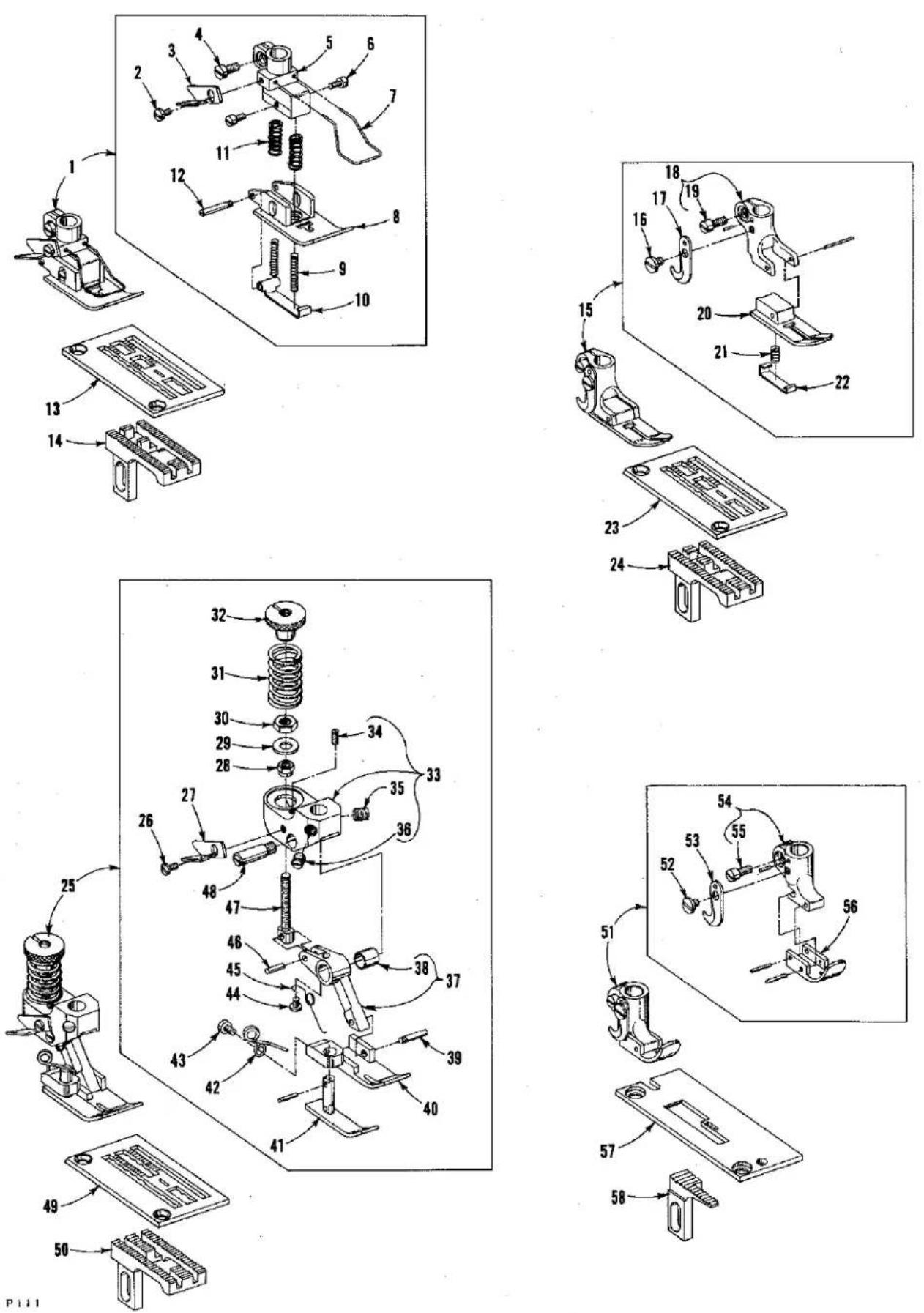
SEWING COMBINATIONS
| Ref.No. | PartNo. | Description | Amt.Req. |
| 1 | C50020 | Presser Foot Assembly, for Styles LF611K100MF and 112MF | 1 |
| 2 | 604 | Screw | 1 |
| 3 | 52930 AC | Knife, chain cutter | 1 |
| 4 | 22562 | Screw | 1 |
| 5 | C50030 | Shank, presser foot | 1 |
| 6 | 22784 M | Screw | 1 |
| 7 | C50031 | Guard, finger | 1 |
| 8 | C50030 A | Bottom, presser foot | 1 |
| 9 | C50030 D | Spring | 2 |
| 10 | C50030 B | Section, yielding | 1 |
| 11 | C50030 C | Spring | 2 |
| 12 | 22799 B | Screw, hinge | 1 |
| 13 | 50324 | Throat Plate, for Styles LF611K100MF and 112MF | 1 |
| 14 | C50005 F | Feed Dog, for Styles LF611K100MF and 112MF | 1 |
| 15 | G51320 | Presser Foot Assembly, for Styles LF611K100MG and 112MG | 1 |
| 16 | 187 B | Screw | 1 |
| 17 | 1741 B | Knife, chain cutting | 1 |
| 18 | 51330 AJ | Shank, presser foot | 1 |
| 19 | 91 | Screw | 1 |
| 20 | 51330 AG | Bottom, presser foot | 1 |
| 21 | 51330 W | Spring | 1 |
| 22 | 51330 AH | Section, yielding | 1 |
| 23 | C50024 D | Throat Plate, for Styles LF611K100MG and 112MG | 1 |
| 24 | C50005 G | Feed Dog, for Styles LF611K100MG and 112MG | 1 |
| 25 | 56320 H | Presser Foot Assembly, for Style LF611K100MR | 1 |
| 26 | 604 | Screw | 1 |
| 27 | 52930 AC | Knife, chain cutting | 1 |
| 28 | 51430 F | Nut | 1 |
| 29 | 56330 AU | Washer | 1 |
| 30 | 41071 G | Nut, locking | 1 |
| 31 | 56330 AD | Spring | 1 |
| 32 | 56330 AH | Nut, pressure regulating | 1 |
| 33 | 56330 AK | Yoke | 1 |
| 34 | 22785 | Screw | 1 |
| 35 | 22560 B | Screw | 1 |
| 36 | 88 | Screw | 1 |
| 37 | 56330 AN | Link, presser foot | 1 |
| 38 | 56330 AP | Bushing | 1 |
| 39 | 22799 G | Screw | 1 |
| 40 | 56330 AL | Bottom, presser foot | 1 |
| 41 | 56330 AM | Section, yielding | 1 |
| 42 | 56330 AR | Spring, yielding section | 1 |
| 43 | 604 | Screw | 1 |
| 44 | 73 A | Screw | 1 |
| 45 | 56330 AX | Spring, tilting | 1 |
| 46 | 56330 AJ | Pin, hinge | 1 |
| 47 | 56330 AG | Screw, connection | 1 |
| 48 | 56330 AF | Screw, hinge | 1 |
| 49 | C51324 W | Throat Plate, for Style LF611K100MR | 1 |
| 50 | 51305 W | Feed Dog, for Style LF611K100MR | 1 |
| 51 | 51220 W | Presser Foot Assembly, for Style LF611K100MW | 1 |
| 52 | 187 B | Screw | 1 |
| 53 | 1741 B | Knife, chaining cutting | 1 |
| 54 | 51230 F | Shank, presser foot | 1 |
| 55 | 91 | Screw | 1 |
| 56 | 51230 G | Bottom, presser foot | 1 |
| 57 | C56224 A | Throat Plate, for Style LF611K100MW | 1 |
| 58 | 51205 W | Feed Dog, for Style LF611K100MW | 1 |
text_image
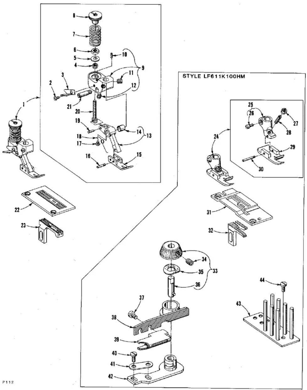
STYLE LF611K100HM P112SEWING COMBINATIONS
| Ref. No. | Part No. | Description | Amt. Req. |
| 1 | 56320 E | Presser Foot Assembly, for Style LF611K100MAW ---- | 1 |
| 2 | 604 | Screw ---- | 1 |
| 3 | 52930 AC | Knife, chain cutting ---- | 1 |
| 4 | 51430 F | Nut ---- | 1 |
| 5 | 56330 AU | Washer ---- | 1 |
| 6 | 41071 G | Nut ---- | 1 |
| 7 | 56330 AD | Spring ---- | 1 |
| 8 | 56330 AH | Nut, pressure regulating ---- | 1 |
| 9 | 56330 AK | Yoke ---- | 1 |
| 10 | 22785 | Screw ---- | 1 |
| 11 | 22560 B | Screw ---- | 1 |
| 12 | 88 | Screw ---- | 1 |
| 13 | 56330 AV | Link, presser foot ---- | 1 |
| 14 | 56330 AP | Bushing ---- | 1 |
| 15 | 56330 AW | Bottom, presser foot ---- | 1 |
| 16 | 22799 G | Screw ---- | 1 |
| 17 | 73 A | Screw ---- | 1 |
| 18 | 56330 AX | Spring, tilting ---- | 1 |
| 19 | 56330 AJ | Pin, hinge ---- | 1 |
| 20 | 56330 AG | Screw, connection ---- | 1 |
| 21 | 56330 AF | Screw, hinge ---- | 1 |
| 22 | C56324 C | Throat Plate, for Style LF611K100MAW ---- | 1 |
| 23 | 56305 C | Feed Dog, for Style LF611K100MAW ---- | 1 |
| 24 | 6420 W | Presser Foot, Complete, for Style LF611K100HM ---- | 1 |
| 25 | 6430 | Shank, presser foot ---- | 1 |
| 26 | 91 | Screw, clamp ---- | 1 |
| 27 | 51430 F | Nut, lock ---- | 1 |
| 28 | 22840 A | Screw, adjusting ---- | 1 |
| 29 | 6430 A | Bottom, presser foot ---- | 1 |
| 30 | 22799 E | Screw, hinge ---- | 1 |
| 31 | C50024 M | Throat Plate, for Style LF611K100HM ---- | 1 |
| 32 | C50005 M | Feed Dog, for Style LF611K100HM ---- | 1 |
| 33 | C50096 C | Knob Assembly, Complete, for Style LF611K100HM ---- | 1 |
| 34 | 22894 C | Screw, Set ---- | 1 |
| 35 | C50096 A | Washer, spring ---- | 1 |
| 36 | C50096 | Pin, clamping ---- | 1 |
| 37 | 90 | Screw, for Style LF611K100HM ---- | 2 |
| 38 | 23437 Z | Bracket, binder, for Style LF611K100HM ---- | 1 |
| 39 | 23215 BG-5/8 | Binder, English, for Style LF611K100HM ---- | 1 |
| 23215 BG-3/4 | Binder, English, for Style LF611K100HM ---- | 1 | |
| 23215 BG-7/8 | Binder, English, for Style LF611K100HM ---- | 1 | |
| 40 | 22585 A | Screw, for Style LF611K100HM ---- | 2 |
| 41 | 23425 T | Plate, clamping, for Style LF611K100HM ---- | 1 |
| 42 | 50396 | Bracket, binder, for Style LF611K100HM ---- | 1 |
| 43 | 23439 A | Pin, tension, for Style LF611K100HM ---- | 1 |
| 44 | 90 | Screw, for Style LF611K100HM ---- | 2 |

text_image
Technical diagram of a mechanical assembly with numbered components and exploded viewsPOWER "AIR-KLIPP®" CHAIN CUTTER AND RELATED PARTS
(Styles LF611K112MF and LF611K112MG ONLY)
| Ref. No. | Part No. | Description | Amt. Req. |
| 1 | 50382 Y | Cover, suction tube | 1 |
| 2 | 99312 A | Screw | 3 |
| 3 | 22525 E | Screw | 4 |
| 4 | 50301 T | Plate, cloth, left | 1 |
| 5 | 50332 E | Bracket | 1 |
| 6 | 22526 | Screw | 2 |
| 7 | 99677 UA | Inlet, thread | 1 |
| 8 | 77 F | Screw | 1 |
| 9 | 22569 F | Screw | 1 |
| 10 | 50382 Z | Cover, plate | 1 |
| 11 | 50382 D | Gasket | 1 |
| 12 | 22653 B-8 | Screw | 6 |
| V29944 C | Power "Air-Klipp" Assembly (complete) | 1 | |
| 13 | 99679 UA | Cover | 1 |
| 14 | 99372 A | Screw, adjusting | 1 |
| 15 | 99697 TA | Spring | 1 |
| 16 | 99666 TA | Lever, knife | 1 |
| 17 | 99322 | Nut | 1 |
| 18 | 99672 UE | Block, sliding | 1 |
| 19 | 99691 TA | Housing, chain cutter | 1 |
| 20 | 80265 | Washer | 2 |
| 21 | 22729 J | Screw | 2 |
| 22 | 95435 A | Screw | 2 |
| 23 | 99670 TH | Knife, upper | 1 |
| 24 | 99669 TH | Knife, lower | 1 |
| 25 | 99672 UD | Lever | 1 |
| 26 | 99672 TC | Insert, plastic | 1 |
| 27 | 671 H-4D | Connection | 1 |
| 28 | 95954 | Washer | 1 |
| 29 | 96280 | Ring, retaining | 3 |
| 30 | 22562 A | Screw | 1 |
| 31 | 99672 UB-2 | Clamp, (rear) | 1 |
| 32 | HS100 D | Screw, stud | 1 |
| 33 | 99672 UB-1 | Clamp, (front) | 1 |
| 34 | 96275 | Ring, retaining | 1 |
| 35 | 22517 | Screw | 2 |
| 36 | 80557 | Washer | 2 |
| 37 | 671 H-4 | Air-Motor Assembly | 1 |
| 38 | 22585 | Screw | 2 |
| 39 | 671 H-1E | Screw, plug | 1 |
| 40 | 99646 BA | Collar, thrust | 2 |
| 41 | 671 H-4C | Rod, piston | 1 |
| 42 | 660-206 | "0" Ring | 1 |
| 43 | 671 H-1A | Piston | 1 |
| 44 | 660-753 | Spring | 1 |
| 45 | 671 H-1F | Washer, bumper | 1 |
| 46 | 671 H-1D | Screw, plug | 1 |
| 47 | 671 H-2A | Housing | 1 |
| 48 | 671 H-4A | Bracket, housing | 1 |
| 49 | 660-400 | Fitting, straight | 2 |
| 50 | 99675 G 1000 | Tubing, plastic | 1 |
| 51 | 999-126 G | Connector, straight | 1 |
| 52 | 999-140 C | Muffler | 1 |
text_image
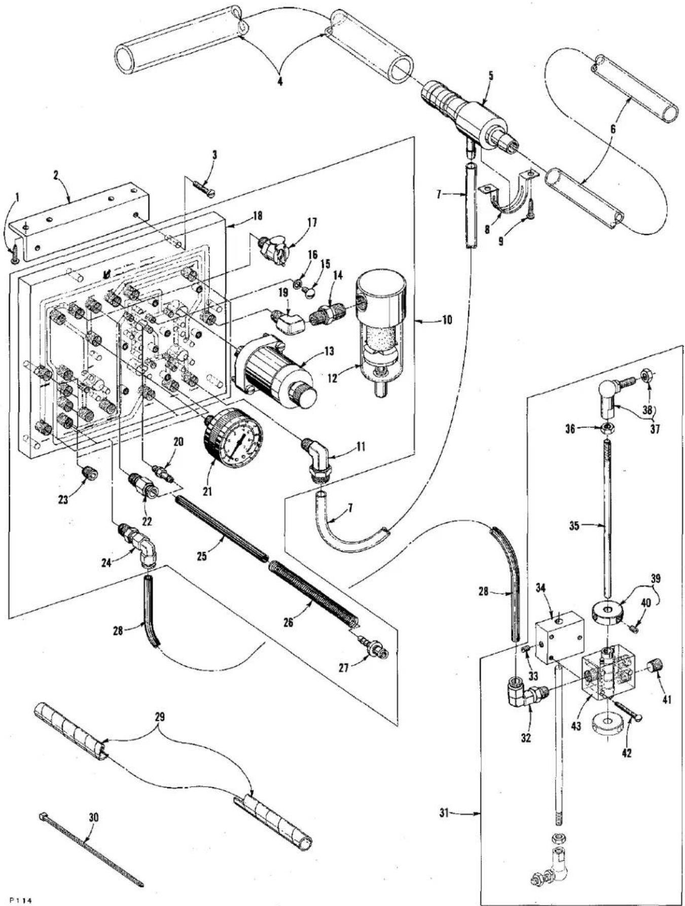
Technical schematic diagram of a mechanical assembly with numbered components and labeled partsPNEUMATIC CONTROLS
(Styles LF611K112MF and LF611K112MG ONLY)
| Ref.No. | PartNo. | Description | Amt.Req. |
| 1 | RM2719-1 | Screw, wood ---- | 2 |
| 2 | 671 G-3 | Bracket, mounting ---- | 1 |
| 3 | 22835 | Screw ---- | 2 |
| 4 | 671 B-11 | Tube, discharge ---- | 1 |
| 5 | 671 D-2 | Venturi ---- | 1 |
| 6 | 671 B-12 | Tube, suction ---- | 1 |
| 7 | 671 B-3 | Tube, venturi air supply ---- | 1 |
| 8 | 998-332 | Holder, venturi ---- | 1 |
| 9 | RM2719-1 | Screw, wood ---- | 2 |
| 10 | 29480 WW | Pneumatic Control Board Assembly ---- | 1 |
| 11 | 671 F-3 | Connector ---- | 1 |
| 12 | 671 D-5 | Filter, air line ---- | 1 |
| 13 | 671 D-30 | Regulator, pressure ---- | 3 |
| 14 | RM3320-1 | Fitting, reducer ---- | 1 |
| 15 | 22649 F-16 | Screw ---- | 1 |
| 16 | RM2964 B | Washer, fiber ---- | 1 |
| 17 | 660-971 | Coupling Body ---- | 3 |
| 18 | 671 D-29 | Control Board ---- | 1 |
| 19 | RM2881-1 | Fitting, elbow; 90 degree ---- | 1 |
| 20 | 671 F-4 | Fitting, barb ---- | 2 |
| 21 | 671 D-10 | Gauge, pressure ---- | 1 |
| 22 | 671 F-67 | Fitting, straight ---- | 1 |
| 23 | 22571 F | Screw, plug ---- | 4 |
| 24 | 671 F-69 | Fitting, elbow; 90 degree ---- | 4 |
| 25 | RM2997 D | Tubing, air; 1/4 inch (6.35mm) O.D. 5 inches(127mm) long ---- | 2 |
| 26 | 39530 AL | Spring ---- | 2 |
| 27 | 671 F-68 | Fitting, tube (plastic) ---- | 1 |
| 28 | RM2997 D | Tubing, air; 1/4 inch (6.35mm) O.D. (Specify length)---- as req. | |
| 29 | RM3832-1 | Wrap, harness ---- | 1 |
| 30 | RM2871 B | Tie ---- | 4 |
| 31 | 29480 XU | Foot Treadle Valve Assembly ---- | 1 |
| 32 | 671 F-69 | Fitting, elbow; 90 degree ---- | 2 |
| 33 | 22894 R | Screw ---- | 1 |
| 34 | 671-91 | Block, mounting bracket ---- | 1 |
| 35 | 99563 A-155 | Rod, pitman ---- | 2 |
| 36 | 95250 | Nut ---- | 2 |
| 37 | 999-146 | Link ---- | 2 |
| 38 | 95250 | Nut ---- | 2 |
| 39 | C50036 AS | Collar, actuating ---- | 2 |
| 40 | 22894 R | Screw ---- | 2 |
| 41 | 22571 F | Screw, plug ---- | 1 |
| 42 | SC-191 | Screw ---- | 3 |
| 43 | 671-90 | Body, valve ---- | 1 |
text_image
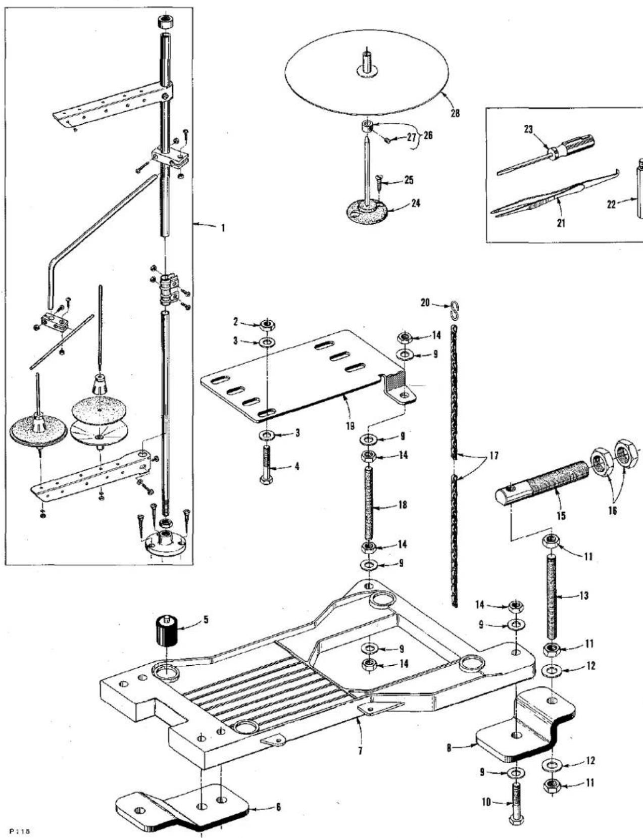
Technical diagram of a mechanical assembly with numbered parts and exploded views, likely from an engineering manual.THREAD STAND AND ACCESSORIES
| Ref. No. | Part No. | Description | Amt. Req. |
| 1 | 21101 W-2 | Thread Stand Assembly | 1 |
| 2 | 50335 T | Nut | 1 |
| 3 | 652-16 | Washer | 3 |
| 4 | 22788 H | Bolt | 3 |
| 5 | 35095 B | Isolator | 4 |
| 6 | 21374 AP | Support | 2 |
| 7 | 21374 AG | Cradle, machine | 1 |
| 8 | 21374 AU | Support | 1 |
| 9 | RM3293-3 | Washer | 16 |
| 10 | 22641 | Bolt | 5 |
| 11 | RM3211-5 | Nut | 9 |
| 12 | RM3293-4 | Washer | 4 |
| 13 | 21374 AT | Rod, threaded | 3 |
| 14 | RM3211-3 | Nut | 3 |
| 15 | 21374 AM | Rod | 4 |
| 16 | 651 M | Nut | 8 |
| 17 | 421 D-42 | Chain, presser foot lift | 1 |
| 18 | 21371 PY-32 | Rod, threaded | 1 |
| 19 | 21374 BB | Bracket, motor mounting | 1 |
| 20 | 660-264 | Hook, "S" | 2 |
| 21 | 660-240 | Tweezer, thread | 1 |
| 22 | 22841 M | Stand, machine | 4 |
| 23 | 21207 B | Screwdriver | 1 |
| 24 | 21169 F | Base, binding holder, for Style LF611K100HM | 1 |
| 25 | SC303 | Screw, for Style LF611K100HM | 2 |
| 26 | 161 | Collar, for Style LF611K100HM | 1 |
| 27 | 88 | Screw | 1 |
| 28 | 21169 E | Disc, binding holder, for Style LF611K100HM | 1 |
| 28604 R | Container of oil, 16 ounces (455 ml.), Spec. 175,(not shown) | 1 |
NUMERICAL INDEX OF PARTS
| Part No. | Page No. | Part No. | Page No. | Part No. | Page No. | |
| W0-3 | 23 | 660-257 | 37 | 671 | H-1E | 45 |
| 18-71 | 29 | 660-264 | 49 | 671 | H-1F | 45 |
| 18-799 | 37 | 660-400 | 45 | 671 | H-2A | 45 |
| 20 | 37 | 660-455 | 23,31 | 671 | H-4 | 45 |
| 24 | 37 | 660-680 | 29 | 671 | H-4A | 45 |
| 25 | 37 | 660-684 | 23 | 671 | H-4C | 45 |
| 25 S | 29,31,37 | 660-708 | 29 | 671 | H-4D | 45 |
| 25 TB | 37 | 660-713 | 29 | 820 | 23 | |
| 51-627 BLK | 25 | 660-718 | 39 | 998-332 | 47 | |
| 51-794 BLK | 25 | 660-739 | 25 | 999-126 G | 45 | |
| C067 B | 25 | 660-753 | 45 | 999-140 C | 45 | |
| C067 D | 29 | 660-885 | 31 | 999-146 | 47 | |
| 73 A | 33,41,43 | 660-934 | 31 | 999-211 C | 35 | |
| 74 E | 23,25 | 660-935 | 31 | 999-211 E | 23 | |
| 77 F | 45 | 660-939 | 27 | 999-216 C | 27 | |
| 77 K | 35 | 660-969 | 35 | 1741 B | 41 | |
| 79-31 | 23 | 660-971 | 47 | RM2719-1 | 47 | |
| J80 K | 29 | 660-979 | 31 | RM2871 B | 47 | |
| 87 | 27 | 660-980 | 35 | RM2879-2 | 27 | |
| 88 | 41,43,49 | 660-986 | 33,39 | RM2881-1 | 47 | |
| 88 B | 29 | 660-998 | 31 | RM2964 B | 47 | |
| 89 | 23,33 | 661-26 | 37 | RM2997 D | 47 | |
| 90 | 31,43 | 661-35 | 35 | RM3211-3 | 49 | |
| 91 | 41,43 | 661-50 | 35 | RM3211-5 | 49 | |
| 93 | 27 | 661-51 | 23 | RM3293-3 | 49 | |
| 94 | 27 | 666-214 | 31 | RM3293-4 | 49 | |
| 95 | 31 | 666-310 | 23 | RM3320-1 | 47 | |
| 97 | 23 | 666-311 | 25 | RM3832-1 | 47 | |
| HS100 D | 45 | 667 J-33 | 31 | 6042 A | 23,31 | |
| 109 | 37 | 667 M-14 | 39 | 6420 W | 43 | |
| 128 GAS | 29 | 668-885 | 23 | 6430 | 43 | |
| 128 GBS | 29 | 670 E-2 | 23 | 6430 A | 43 | |
| 136 A | 25 | 671-90 | 47 | 12934 A | 27,39 | |
| 157-15 | 33 | 671-91 | 47 | 21101 W-2 | 49 | |
| 161 | 49 | 671 B-3 | 47 | 21169 E | 49 | |
| 187 B | 41 | 671 B-11 | 47 | 21169 F | 49 | |
| SC191 | 47 | 671 B-12 | 47 | 21207 B | 49 | |
| 258 | 23 | 671 D-2 | 47 | 21210 | 31 | |
| SC303 | 49 | 671 D-5 | 47 | 21371 PY-32 | 49 | |
| 421 D-42 | 49 | 671 D-10 | 47 | 21374 AG | 49 | |
| 531 | 39 | 671 D-29 | 47 | 21374 AM | 49 | |
| 604 | 25,41,43 | 671 D-30 | 47 | 21374 AP | 49 | |
| 605 A | 37 | 671 F-3 | 47 | 21374 AT | 49 | |
| 651 M | 49 | 671 F-4 | 47 | 21374 AU | 49 | |
| 652-16 | 49 | 671 F-41 | 23 | 21374 BB | 49 | |
| 660-206 | 23,31,35,45 | 671 F-67 | 47 | 21657 E | 37 | |
| 660-212 | 31 | 671 F-68 | 47 | 22501 A | 37 | |
| 660-219 A | 27 | 671 F-69 | 47 | 22513 | 37 | |
| 660-220 | 31 | 671 G-3 | 47 | 22517 | 27,45 | |
| 660-240 | 49 | 671 H-1A | 45 | 22519 J | 37 | |
| 671 H-1D | 45 | 22525 E | 27,45 |
NUMERICAL INDEX OF PARTS
| Part No. | Page No. | Part No. | Page No. | Part No. | Page No. |
| 22526 | 45 | 22729 | 31 | 28604 | R. 49 |
| 22526 | H. 27 | 22729 | 45 | 29105 | AT. 31 |
| 22533 | A. 25 | 22729 | 35 | 29126 | EV. 35 |
| 22539 | G. 25 | 22743 | 31 | 29126 | FB. 35 |
| 22541 | 23 | 22757 | 37 | 29192 | AE. 31 |
| 22541 | C. 27 | 22758 | 39 | 29476 | PG. 37 |
| 22560 | B. 35,41,43 | 22764 | 35 | 29480 | WW. 47 |
| 22562 | 41 | 22764 | 25 | 29480 | XU. 47 |
| 22562 | A. 45 | 22768 | 33 | V29944 | C. 45 |
| 22565 | 25 | 22768 | 29 | 35021 | 31 |
| 22565 | X. 31 | 22781 | 33 | 35021 | B. 31 |
| 22569 | B. 37 | 22784 | 41 | 35034 | J. 35 |
| 22569 | C. 37,39 | 22785 | 41,43 | 35034 | M. 35 |
| 22569 | D. 27,33,37 | 22788 | 49 | 35034 | N. 35 |
| 22569 | F. 45 | 22792 | 37 | 35036 | C. 35 |
| 22569 | G. 31 | 22797 | 33 | 35036 | F. 35 |
| 22569 | M. 27 | 22798 | 33 | 36036 | X. 23 |
| 22569 | AD. 35 | 22799 | 41 | 35036 | AB. 25 |
| 22570 | 27 | 22799 | 43 | 35036 | AE. 27 |
| 22571 | D. 35 | 22799 | 41,43 | 35036 | AP. 35 |
| 22571 | E. 23 | 22799 | 27,37 | 35036 | AZ. 35 |
| 22571 | F. 47 | 22830 | 31 | 35039 | A. 23 |
| 22571 | J. 23 | 22835 | 47 | 35040 | B-15. 35 |
| 22575 | B. 31 | 22839 | 27 | 35040 | B-22. 35 |
| 22585 | 45 | 22840 | 43 | 35042 | A. 29 |
| 22585 | A. 43 | 22840 | 39 | 35042 | C. 29 |
| 22585 | C. 29 | 22841 | 23,49 | 35055 | V. 31 |
| 22586 | 23,25 | 22841 | 27 | 35082 | B. 23 |
| 22587 | N. 27 | 22861 | 27 | 35082 | E. 27 |
| 22588 | A. 33 | 22882 | 39 | 35082 | F. 27 |
| 22588 | S. 33 | 22883 | 27 | 35093 | F. 23 |
| 22591 | 29,35 | 22894 | 23,25,29,31,33,35,43 | 35093 | H. 23 |
| 22591 | A. 35 | 35093 | J. 23 | ||
| 22596 | 39 | 35093 | P. 29 | ||
| 22596 | E. 29,35,39 | 22894 | 27,33 | 35094 | A. 23 |
| 22617 | J-16. 35 | 22894 | 23,27,35 | 35095 | B. 49 |
| 22637 | P-24. 35 | 22894 | 31 | 35569 | J. 37 |
| 22641 | 49 | 22894 | 39 | 39530 | AL. 47 |
| 22649 | F-16. 47 | 22894 | 39 | 39592 | AK. 37 |
| 22650 | CD-6. 31 | 22894 | 47 | 41071 | G. 41,43 |
| 22652 | A-4. 23 | 22894 | 39 | C50004 | C. 37 |
| 22652 | A-8. 31 | 22894 | 29,31 | C50005 | F. 41 |
| 22652 | B-10. 31 | 22894 | 35 | C50005 | G. 41 |
| 22653 | B-8. 27,45 | 22894 | 29,31 | C50005 | M. 43 |
| 22653 | B-36. 23 | 22894 | 31 | C50017 | C. 29 |
| 22653 | J-8. 31 | 23215 | 43 | C50018 | D. 29 |
| 22655 | B-7. 29 | 23215 | 43 | C50020 | 41 |
| 22706 | C. 25,29 | 23215 | 43 | C50021 | A. 29 |
| 22714 | C. 35 | 23425 | 43 | C50024 | D. 41 |
| 22720 | A. 23,29 | 23437 | 43 | C50024 | M. 43 |
| 22720 | C. 29 | 23439 | 43 | C50030 | 41 |
NUMERICAL INDEX OF PARTS
| Part No. | Page No. | Part No. | Page No. | Part No. | Page No. |
| C50030 A | 41 | C50093 U | 23 | 50334 K | 35 |
| C50030 B | 41 | C50093 Z | 23 | 50334 W | 35 |
| C50030 C | 41 | C50093 AU | 27 | 50334 Y | 35 |
| C50030 D | 41 | C50093 AX | 25 | 50334 AA | 35 |
| C50031 | 41 | C50093 AY | 25,29 | 50334 AB | 35 |
| C50035 Z | 25 | C50093 CA | 23 | 50335 | 35 |
| C50036 P | 29 | C50093 CB | 23 | 50335 A | 35 |
| C50036 R | 39 | C50093 CJ | 23,29 | 50335 C | 35 |
| C50036 AS | 47 | C50093 CN | 25 | 50335 D | 35 |
| C50042 AD | 31 | C50093 CT | 25 | 50335 E | 35 |
| C50044 E | 37 | C50094 B | 23 | 50335 L | 35 |
| C50044 V | 31 | C50094 C | 23 | 50335 T | 49 |
| C50054 D | 25 | C50094 R | 23 | 50336 C | 35 |
| C50054 M | 37 | C50094 X | 29 | 50336 D | 35 |
| C50055 H | 25,29 | C50094 Y | 23 | 50339 | 31 |
| C50056 B | 39 | C50094 AK | 23 | 50342 A | 31 |
| C50056 C | 39 | C50095 D | 27 | 50342 B | 31 |
| C50056 D | 39 | C50095 E | 27 | 50342 D | 31 |
| C50056 J | 39 | C50095 F | 27 | 50342 E | 33 |
| C50056 K | 39 | C50095 G | 27 | 50342 F | 33 |
| C50057 D | 25 | C50096 | 43 | 50342 H | 31 |
| C50057 E | 39 | C50096 A | 43 | 50342 R | 29 |
| C50058 F | 37 | C50096 C | 43 | 50343 | 31 |
| C50058 H | 29 | 50301 | 27 | 50344 B | 25 |
| C50058 R | 37 | 50301 A | 27 | 50344 C | 31 |
| C50067 B | 39 | 50301 B | 27 | 50344 E | 25 |
| C50067 G | 39 | 50301 R | 27 | 50344 F | 25 |
| C50067 K | 39 | 50301 T | 45 | 50344 G | 25 |
| C50068 AR | 31 | 50304 A | 33 | 50344 H | 33 |
| C50070 E | 37 | 50313 | 31 | 50344 K | 25 |
| C50077 P | 33 | 50314 | 31 | 50344 L | 25 |
| C50082 K | 27 | 50314 A | 31 | 50354 | 29 |
| C50082 M | 27 | 50322 B | 39 | 50354 B | 25 |
| C50082 N | 27 | 50322 C | 39 | 50354 C | 25 |
| C50082 R | 27 | 50322 K | 35 | 50355 | 35 |
| C50082 V | 27 | 50322 AA | 31 | 50355 G | 29 |
| C50082 X | 27 | 50323 | 33 | 50355 H | 29 |
| C50082 AA | 27 | 50323 A | 33 | 50355 L | 25 |
| C50082 AW | 27 | 50323 B | 33 | 50355 P | 29 |
| C50090 M | 39 | 50323 C | 33 | 50355 T | 29 |
| C50092 G | 37 | 50323 D | 33 | 50357 | 33 |
| C50092 J | 37 | 50324 | 41 | 50357 A | 33 |
| C50092 L | 37 | 50325 | 31 | 50357 B | 33 |
| C50092 M | 37 | 50332 | 33 | 50357 D | 33 |
| C50092 R | 37 | 50332 A | 37 | 50357 F | 33 |
| C50092 S | 37 | 50332 B | 37 | 50357 G | 33 |
| C50093 F | 23 | 50332 E | 45 | 50357 H | 33 |
| C50093 G | 23 | 50334 A | 35 | 50358 | 37 |
| C50093 R | 23 | 50334 B | 35 | 50367 | 39 |
| C50093 S | 23 | 50334 C | 35 | 50367 A | 39 |
| C50093 T | 23 | 50334 F | 35 | 50367 B | 39 |
NUMERICAL INDEX OF PARTS
| Parts No. | Page No. | Parts No. | Page No. | Parts No. | Page No. |
| 50367 E | 39 | 50393 AW | 23 | 56330 AM | 41 |
| 50368 | 31 | 50393 AX | 23 | 56330 AN | 41 |
| 50368 A | 31 | 50393 AY | 23 | 56330 AP | 41,43 |
| 50368 B | 25 | 50393 BA | 23 | 56330 AR | 41 |
| 50368 C | 31 | 50393 BB | 23 | 56330 AU | 41,43 |
| 50368 D | 31 | 50393 BK | 23 | 56330 AV | 43 |
| 50368 E | 31 | 50394 B | 23 | 56330 AW | 43 |
| 50378 | 37 | 50394 G | 23 | 56330 AX | 41,43 |
| 50380 | 27 | 50394 J | 27 | 56358 D | 37 |
| 50380 D | 27 | 50394 K | 23 | 56392 F | 37 |
| 50382 A | 27 | 50394 L | 23 | 57847 | 31 |
| 50382 C | 37 | 50394 S | 25 | 62245 C | 31 |
| 50382 D | 27,45 | 50396 | 43 | 80265 | 45 |
| 50382 E | 27 | 51205 W | 41 | 80557 | 45 |
| 50382 F | 27 | 51208 | 31 | 80630 D | 29 |
| 50382 G | 27 | 51220 W | 41 | 95250 | 47 |
| 50382 H | 27 | 51230 F | 41 | 95435 A | 45 |
| 50382 J | 27 | 51230 G | 41 | 95954 | 45 |
| 50382 T | 37 | 51280 K | 27 | 96275 | 45 |
| 50382 Y | 45 | 51292 A | 37 | 96280 | 45 |
| 50382 Z | 45 | 51292 F-1 | 37 | 97127 | 27 |
| 50382 AA | 37 | 51292 F-4 | 37 | 99277 | 35 |
| 50382 AM | 37 | 51305 W | 41 | 99312 A | 45 |
| 50382 EA | 27 | G51320 | 41 | 99322 | 45 |
| 50390 | 25 | C51324 W | 41 | 99372 A | 45 |
| 50390 A | 25 | 51330 W | 41 | 99521 | 33 |
| 50390 B | 39 | 51330 AG | 41 | 99563 A-155 | 47 |
| 50390 C | 25 | 51330 AH | 41 | 99646 BA | 45 |
| 50390 D | 25 | 51330 AJ | 41 | 99666 TA | 45 |
| 50390 E | 39 | G51409 C | 31 | 99669 TH | 45 |
| 50392 | 37 | 51430 F | 41,43 | 99670 TH | 45 |
| 50392 A | 37 | 51858 | 37 | 99672 TC | 45 |
| 50392 B | 37 | 51909 C | 31 | 99672 UB-1 | 45 |
| 50393 A | 23 | 52804 E | 33 | 99672 UB-2 | 45 |
| 50393 C | 23 | 52904 E | 33 | 99672 UD | 45 |
| 50393 D | 23 | 52930 AC | 41,43 | 99672 UE | 45 |
| 50393 E | 23 | 52958 D | 33 | 99675 G 1000 | 45 |
| 50393 F | 23 | 53678 N | 29,33 | 99677 UA | 45 |
| 50093 J | 23 | 54274 P | 33 | 99679 UA | 45 |
| 50393 N | 23 | C56224 A | 41 | 99691 TA | 45 |
| 50393 S | 31 | 56305 C | 43 | 99697 TA | 45 |
| 50393 U | 27 | 56320 E | 43 | ||
| 50393 V | 23 | 56320 H | 41 | ||
| 50393 W | 37 | C56324 C | 43 | ||
| 50393 X | 23 | 56330 AD | 41,43 | ||
| 50393 AL | 31 | 56330 AF | 41,43 | ||
| 50393 AN | 31 | 56330 AG | 41,43 | ||
| 50393 AR | 23 | 56330 AH | 41,43 | ||
| 50393 AT | 23 | 56330 AJ | 41,43 | ||
| 50393 AU | 23 | 56330 AK | 41,43 | ||
| 50393 AV | 23 | 56330 AL | 41 |
MACHINE INVENTORY INFORMATION
| Unit Number | Maker's Name | Machine Style | Serial Number | Needle Type | Date Of Purchase |
ADDITIONAL INFORMATION:
Notes:

natural_image
World map of the Americas and surrounding oceans and equatorial regions, showing continents and latitude/longitude lines (no text labels)WORLDWIDE SALES AND SERVICE
Union Special Corporation maintains sales and service facilities throughout the world. These offices will aid you in the selection of the right sewing equipment for your particular operation. Union Special Corporation representatives and servicemen are factory trained and are able to serve your needs promptly and efficiently. Whatever your location, there is a Union Special Corporation representative to serve you. Check with him today.
It is important to remember that LEWIS® and COLUMBIA® machines are also products of Union Special Corporation, thus offering the industry the most complete line of the Finest Quality sewing machines.
Gainesville, GA
Norcross, GA
Chicago, IL
Dallas, TX
Commerce, CA
Philadelphia, PA
Opa-Locka, FL
Montreal, Quebec
Toronto, Ontario
Brussels, Belgium
Leicester, England
Paris, France
Stuttgart, W. Germany
Milano, Italy
Hong Kong
Osaka, Japan
Other Representatives throughout
all parts of the world
U Union Specials
Union Special Corporation, One Union Special Plaza, Huntley, IL 60142, U.S.A. Union Special, GmbH, Schwabstrasse 33, D-7000 Stuttgart 1, West Germany.