39500QS - Nähmaschine Union Special - Kostenlose Bedienungsanleitung
Finden Sie kostenlos die Bedienungsanleitung des Geräts 39500QS Union Special als PDF.

Benutzerfragen zu 39500QS Union Special
0 Frage zu diesem Gerät. Beantworten Sie die, die Sie kennen, oder stellen Sie Ihre eigene.
Eine neue Frage zu diesem Gerät stellen
Laden Sie die Anleitung für Ihr Nähmaschine kostenlos im PDF-Format! Finden Sie Ihr Handbuch 39500QS - Union Special und nehmen Sie Ihr elektronisches Gerät wieder in die Hand. Auf dieser Seite sind alle Dokumente veröffentlicht, die für die Verwendung Ihres Geräts notwendig sind. 39500QS von der Marke Union Special.
BEDIENUNGSANLEITUNG 39500QS Union Special
FIRST EDITION

Union Special® INDUSTRIAL SEWING EQUIPMENT
CATALOG NO. 103QS
STYLES
39500QS
39500QT
39500RD
39500RL
39500RT
39500TJ
39500TK
39500TM
39500TT
MARK IV HIGH SPEED OVERSEAMERS WITH
DIFFERENTIAL OR INTERMITTENT
DIFFERENTIAL FEED
Here are Oil Specifications for Union Special Sewing Machines
Specification 174 specifies a high quality petroleum oil, viscosity 100 seconds at 100^ . Recommended for all oiling applications on high speed machines.
Specification 175 specifies a high quality petroleum oil, viscosity 100 seconds at 100^ , water white or with a maximum A.S.T.M. color number of 1. For use where freedom from oil staining is paramount.
Specification 87 specifies a high quality petroleum oil, viscosity 300 seconds at 100°F.
Specification 100 specifies a general purpose high quality grease for use in ball bearings and transmitters. It is similar to commercial N.L.G.I., grease No. 3. Where No. 3 grease is not obtainable, No. 2 may be used.
UNION SPECIAL
| SPECIFICATION NO. | 174 | 175 | 87 |
| Viscosity S.S.U. at 100°F | 90-125 | 90-125 | 300-350 |
| Flash (Min.) | 350 | 350 | 350 |
| Pour (Max.) | 20 | 20 | 20 |
| Color A.S.T.M. (Max.) | 3 | 1 | 3 |
| Neutralization No. (Max.) | 0.10 | 0.10 | 0.10 |
| Viscosity Index(D & D Min.) | 85 | 85 | 85 |
| Compounding | None | None | None |
| Copper Corrosion (Max.) | 1A | 1A | 1A |
| *Anline No. | 175-225 | 175-225 | 175-225 |
*Used with Buna N Rubber "O" Retainers

natural_image
Black-and-white portrait of a smiling woman standing beside a railing (no visible text or symbols)NOTE 1: The use of non-corrosive additives in oils meeting above classification is desirable but not essential. These may include:
- Oxidation inhibitors
- Rust inhibitors
- Lubricity additives
- Anti-oxidants
- Film strength additives
These additives must be completely soluble in the oil and not removable by wick feeding nor shall they separate.
NOTE 2: Oils containing the following type additives shall not be used at any time:
- Extreme pressure additives—corrosive
- Tackiness or adhesive additives
- Lead soap additives
- Detergents

FINEST QUALITY
UNION SPECIAL
CORPORATION
Catalog No. 103 QS
INSTRUCTIONS
FOR
ADJUSTING AND OPERATING
LIST OF PARTS
CLASS 39500
Styles
| 39500 QS | 39500 RT |
| 39500 QT | 39500 TJ |
| 39500 RD | 39500 TK |
| 39500 RL | 39500 TM |
| 39500 TT | |
First Edition
Copyright © 1974
By
Union Special Corporation
Rights Reserved in All Countries
UNION SPECIAL CORPORATION
INDUSTRIAL SEWING MACHINES
CHICAGO
Printed in U.S.A.
October, 1978
IDENTIFICATION OF MACHINES
Each UNION SPECIAL machine is identified by a Style number on a name plate on the machine. Style numbers are classified as standard and special. Standard Style numbers have one or more letters suffixed, but never contain the letter "Z". Example: "Style 39500 QS". Special Style numbers contain the letter "Z". When only minor changes are made in a standard machine, a "Z" is suffixed to the standard Style number. Example: "Style 39500 QSZ".
Styles of machines similar in construction are grouped under a Class number which differs from the Style number in that it contains no letters. Example: "Class 39500".
APPLICATION OF CATALOG
This catalog applies specifically to the standard Styles of machines as listed herein. It can also be applied with discretion to some Special Styles of machines in Class 39500. References to directions, such as right, left, front, back, etc., are given from the operator's position while seated at the machine. Operating direction of handwheel is away from operator.
STYLES OF MACHINES
MARK IV Hi-Styled High Speed, One or Two Curved Blade Needles, Two Looper, Three or Four Thread Overseaming Machine, Differential or Intermittent Differential Feed, Trimming Mechanism with Spring Pressed Lower Knife, Automatic Lubricating System, Improved Air Cooling System.
39500 QS Single needle three thread, medium to heavy duty machine, for seaming and intermittently gathering or shirring on woven and knit materials such as dresses, aprons, lingerie, smocks, nightgowns and similar garments. Knee press controlled tandem intermittent differential feed. Slotted presser foot to separate top and bottom plies. Gathering ratio up to 3 to 1 depending on stitch length. Seam specification, 504-SSa-1; standard width of seam 1/8 inch (3.17 mm); stitch range, 8-20 per inch; cam adjusted main and differential feeds. Maximum recommended speed 6000 R.P.M.
39500 QT Single needle three thread, medium to heavy duty machine, for seaming and intermittently gathering or shirring on woven and knit materials such as dresses, aprons, lingerie, smocks, nightgowns and similar garments. Knee press controlled tandem intermittent differential feed. Independent swing-out pressure plate attachment for shirring. Gathering ratio up to 3 to 1 depending on stitch length. Seam specification, 504-SSa-1; standard width of seam 3/16 inch (4.76 mm); stitch range, 8-20 per inch; cam adjusted main and differential feeds. Maximum recommended speed 6000 R.P.M.
39500 RD Two needle four thread, medium to heavy duty machine, for seaming and intermittently gathering or shirring on woven and knit materials such as dresses, aprons, lingerie, smocks, nightgowns and similar garments. Knee press controlled tandem intermittent differential feed. Independent swing-out pressure plate attachment for shirring. Gathering ratio up to 3 to 1 depending on stitch length. Seam specification, 512-SSa-1; standard width of seam from left needle 17/64 inch (6.75 mm); stitch range, 8-20 per inch; cam adjusted main and differential feeds. Maximum recommended speed 6000 R.P.M.
STYLES OF MACHINES (Continued)
39500 RL Two needle four thread, medium to heavy duty machine, for seaming and intermittently gathering or shirring on woven and knit materials such as dresses, aprons, lingerie, smocks, nightgowns and similar garments. Knee press controlled tandem intermittent differential feed. Independent swing-out pressure plate attachment for shirring. Gathering ratio up to 5 to 1 depending on stitch length. Seam specification, 512-SSa-1; standard width of seam from left needle 17/64 inch (6.75 mm); stitch range, 8-20 per inch; cam adjusted main and differential feeds. Maximum recommended speed 5500 R.P.M.
39500 RT Single needle three thread, medium to heavy duty machine, for seaming and intermittently gathering or shirring on all types of cotton, dacron, rayon and silk fabrics where a 3/32 inch (2.38 mm) turned down hem is desired. Knee press controlled tandem intermittent differential feed. Presser foot has a short curler stitch tongue. Independent swing-out pressure plate attachment for shirring. Gathering ratio up to 2.5 to 1 depending on stitch length. Seam specification, 504 EFe-1 inverted; standard width of seam 3/32 inch (2.38 mm); stitch range, 10-20 per inch; cam adjusted main and differential feeds. Maximum recommended speed 6000 R.P.M.
39500 TJ Single needle three thread, medium to heavy duty machine with straight knife parts, for seaming bulky knit sweaters, heavy knit outerwear and similar garments. Can be used for attaching a reinforcing tape used on shoulder seams of sweaters and similar garments; tape automatically guided by slot in presser foot. Thumbscrew adjustable differential feed. Seam specification, 504-SSa-1; standard width of seam 1/8 inch (3.17 mm); stitch range, 8-20 per inch; cam adjusted main and differential feeds. Maximum recommended speed 6000 R.P.M.
39500 TK Two needle four thread, medium to heavy duty machine for seaming operations on coat linings, pockets, bathing suits, house dresses, children's wear, ladies undergarments, and similar garments of medium to heavy weight woven knitted materials of cotton, wool, silk and synthetics. Upper looper thread is caught by both needles. Thumbscrew adjustable feed which allows either reverse or forward differential feeding. Seam specification, 514-SSa-1; standard width of seam from left needle 17/64 inch (6.75 mm); stitch range, 6-20 per inch; cam adjusted main and differential feeds. Maximum recommended speed 6000 R.P.M.
39500 TM Single needle three thread, medium to heavy duty machine, for seaming and intermittently gathering or shirring on woven and knit materials such as dresses, aprons, lingerie, smocks, nightgowns and similar garments. Knee press controlled tandem intermittent differential feed. Independent swing-out pressure plate attachment for shirring. Gathering ratio up to 5 to 1 depending on stitch length. Seam specification, 504-SSa-1; standard width of seam 3/16 inch (4.76 mm); stitch range 8-20 per inch; cam adjusted main and differential feeds. Maximum recommended speed 5500 R.P.M.
39500 TT Single needle three thread, medium to heavy duty machine, for seaming and intermittently gathering or shirring on woven and knit materials such as dresses, aprons, lingerie, smocks, nightgowns and similar garments. Knee press controlled tandem intermittent differential feed. Independent swing-out pressure plate attachment for shirring. Gathering ratio up to 3 to 1 depending on stitch length. Seam specification 504-SSa-1; standard width of seam 3/16 inch (4.76 mm); stitch range, 8-20 per inch; cam adjusted main and differential feeds. Maximum recommended speed 6000 R.P.M.
SPEED RECOMMENDATION
39500 MARK IV machines have been tested in their complete stitch range at their maximum rated speeds. Varied field conditions, severity and cleanliness of the sewing operation may necessitate operating at a lower speed. When operating from 50-100% machine running cycle and a longer than recommended stitch length, it may be necessary to reduce the machine's speed by 10-15%.
SPEED RECOMMENDATION (Continued)
The MARK IV is a precision manufactured and tested sewing machine. To obtain maximum performance, the machine should be operated at 1000 R.P.M. below maximum recommended speed for the first 20 days of field operation. This will minimize readjustment of precision mechanisms.
OILING
CAUTION! Oil was drained from machine when shipped, so reservoir must be filled before beginning to operate. Oil capacity of Class 39500 is eight to nine ounces. A straight mineral oil of a Saybolt viscosity of 90 to 125 seconds at 100^ Fahrenheit should be used.
Machine is filled with oil at spring cap in top cover. Oil level is checked at sight gauge on front of machine. Red bulb on oil level indicator should show between gauge lines when machine is stationary.
Machine is automatically lubricated. No oiling is necessary, other than keeping main reservoir filled. Check oil daily before the morning start; add oil as required.
To maintain maximum recommended speed and serviceability of this equipment when operating continuously, the oil must be changed at least every six months. In no case should oil remain in machine for more than one year.
The oil drainplug screw is located at back of machine near bottom edge of base. It is a magnetic screw designed to accumulate possible foreign materials which may have entered the crank case. It should be removed and cleaned periodically.
NEEDLES
Each UNION SPECIAL needle has both type and size number. The type number deontes the kind of shank, point, length, groove, finish and other details. The size number, stamped on the needle shank, denotes largest diameter of blade, measured in thousandths of an inch, midway between shank and eye. Collectively, type and size number represent the complete symbol which is given on the label of all needles packaged and sold by Union Special.
Class 39500 machines use a curved blade needle. The standard recommended needle for Styles 39500 QS, QT, RD, RL, TJ, TK, TM and TT is Type 154 GAS, while the standard needle for Style 39500 RT is Type 154 GBS. Below are the type numbers, description and sizes available of the recommended needles.
Type No.
Description and Sizes
154 GAS Round shank, round point, curved blade, standard length, single groove, struck groove, spotted, chromium plated and is available in sizes 055/022, 065/025, 070/027, 075/029, 080/032, 090/036, 100/040, 110/044, 125/049, 140/054, 150/060.
154 GBS Round shank, round point, curved blade, standard length, double groove, struck groove, spotted, chromium plated and is available in sizes 070/027, 075/029, 080/032.
To have needle orders promptly and accurately filled, an empty package, a sample needle, or the type and size number should be forwarded. Use description on label. A complete order would read: "1000 Needles, Type 154 GAS, Size 070/027".
Selection of proper needle size is determined by size of thread used. Thread should pass freely through needle eye in order to produce a good stitch formation.
NEEDLES (Continued)
Success in the operation of UNION SPECIAL machines can be secured only by use of needles packaged under our brand name, Union Special®, which is backed by a reputation for producing highest quality needles in materials and workmanship for more than three-quarters of a century.
CHANGING NEEDLES
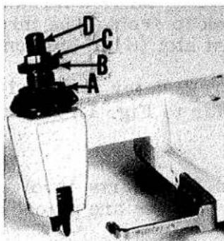
Release pressure on presser foot by turning presser foot release bushing (AG, Fig. 1 or 1A) and swing presser arm (U) out of position. Turn handwheel in operating direction until needle is at its lowest point of travel. Using hexagonal socket wrench No. 21388 AU, furnished with machine, loosen needle clamp nut about 1/4 turn. Again turn handwheel until needle is at high position; withdraw needle.
To replace needle, leave needle holder at high position and, with the flat to the left, insert needle in holder until it rests against stop pin. Keeping needle in this position, turn handwheel until holder is again at its low point of travel; then tighten nut. Return presser arm (U) to position; re-lock presser foot release bushing (AG).
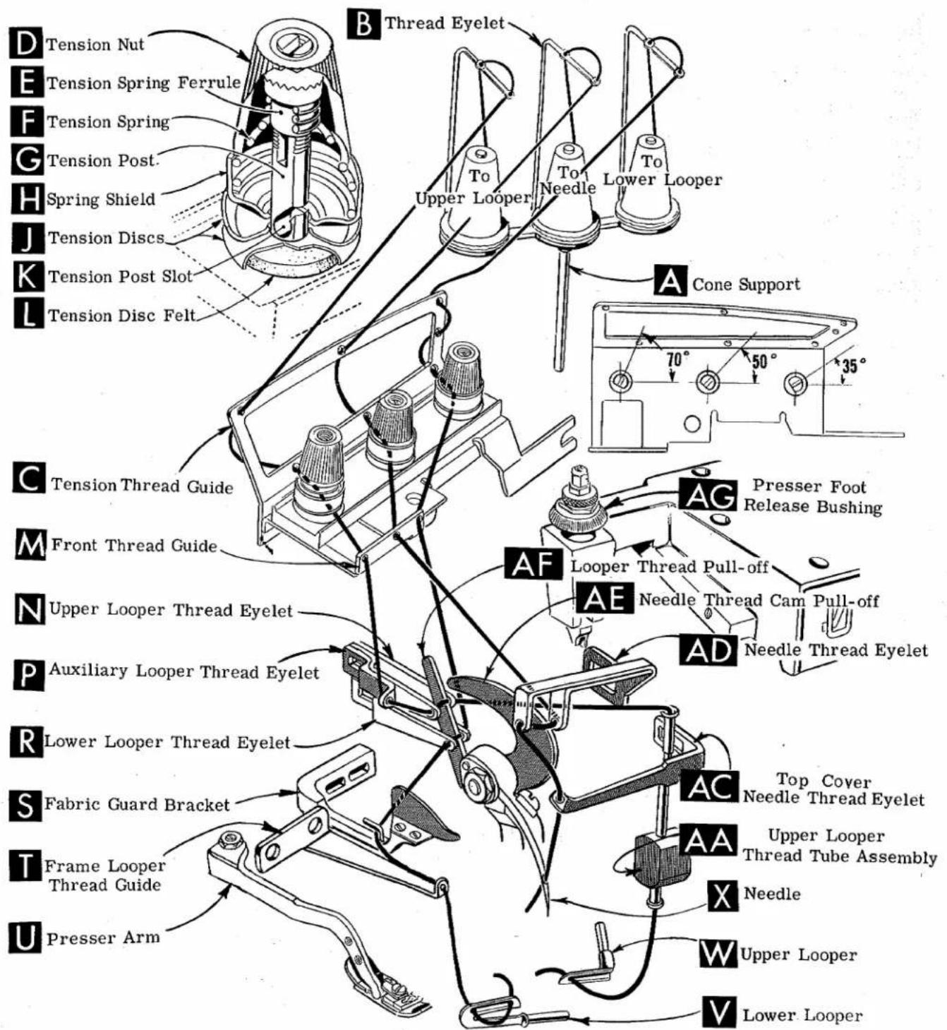
THREAD STAND (504 STITCH)
After thread comes from cones on cone support (A, Fig. 1), it is brought up through back hole of thread eyelet (B), then down through the front hole of thread eyelet. Next it is threaded through the upper holes of tension thread guide (C) from front to back and then through the lower holes from back to front. It should be noted that the lower looper thread is threaded through the tension thread guide (C), first through the upper hole back to front, second through the middle hole front to back and third through the lower hole back to front. All three threads then continue between the tension discs (J), through tension post slot (K) in tension post (G) and on through front thread guide (M).
THREAD STAND (512 AND 514 STITCH)
After thread comes from cones on cone support (A, Fig. 1A), the needle threads are threaded through the back bar of the thread eyelet (B) from back to front, under the middle bar and through the center holes of the front bar. The looper threads come from the cones, through holes of the middle bar from back to front and then through the two outside holes of the front bar. Next it is threaded through the upper holes of tension thread guide (C) front to back and then through the lower holes from back to front. The threads continue between the tension discs (J), through tension post slot (K) in tension post (G) and on through front thread guide (M).
NOTE: Refer to Fig. 1 for threading Styles 39500 QS, QT, RT, TJ, TM and TT, or refer to Fig. 1A for threading Styles 39500 RD, RL and TK.
THREADING
Only parts involved in threading are shown in threading diagrams (Fig. 1 and 1A). Parts are placed in their relative positions for clarity.
It will simplify the threading of these machines to follow the recommended sequence of threading lower looper first, upper looper second, and needle or needles third.
The threading in Fig. 1 and Fig. 1A are the same, the only difference will be the threading of two needle threads in Fig. 1A as compared to one needle thread in Fig. 1. The additional needle in Fig. 1A moves the lower looper thread tension post to the right.
THREADING (Continued)
Before beginning to thread, swing cloth plate open, turn handwheel in operating direction until needle (X) is in high position, release pressure on presser foot by turning presser foot release bushing (AG), and swing presser arm (U) out of position.
Be sure the threads, as they come from the tension thread guide (C), are between the tension discs (J) and in tension post slot (K) in tension post (G). The tension posts should be positioned so the tension post slot will be at the approximate angle for the different threads as indicated in Fig. 1 and 1A.
TO THREAD LOWER LOOPER
Double end of thread and lead it through the right eyelet of front thread guide (M, Fig. 1 or 1A). Then lead it through both eyes of lower looper thread eyelet (R, Fig. 1 or 1A) from right to left. NOTE: Thread must pass in front of looper thread pull-off (AF). Lead thread behind fabric guard (S) and through hole of frame looper thread guide (T). Turn handwheel in operating direction until heel of lower looper (V) is all the way to the left; then thread through both eyes from left to right. Left eye of lower looper can be threaded easily if tweezers are in left hand.
TO THREAD UPPER LOOPER
Thread upper looper thread through left eyelet of front thread guide (M, Fig. 1 or 1A). Turn handwheel until point of upper looper (W) is all the way left. Lead thread through auxiliary looper thread eyelet (P) from back to front, then through both eyes of upper looper thread eyelet (N) from left to right. NOTE: Thread must pass in front of looper thread pull-off (AF). After pulling up upper looper thread tube assembly (AA), lead thread under neck of top cover casting and down through thread tube assembly (AA). Pull thread out bottom of tube; push tube down, then insert thread through upper looper eye from front to back.
CAUTION! Be sure upper looper thread is under lower looper thread when passing from tube assembly to upper looper eye.
TO THREAD THE NEEDLE
Thread needle thread through middle eyelet or eyelets of front thread guide (M, Fig. 1 or 1A). Turn handwheel in operating direction until needle (X) is at its highest position. Insert needle thread or threads from right to left, through both eyes of needle thread eyelet (AD), under neck of top cover casting; and then down through hole or holes in top cover needle thread eyelet (AC). Thread needle from front.
THREAD TENSION
The amount of tension on needle and looper threads is regulated by tension nuts (D, Fig. 1 or 1A). Tension on threads should be only enough to secure proper stitch formation.
PRESSER FOOT PRESSURE
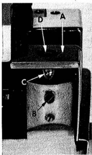
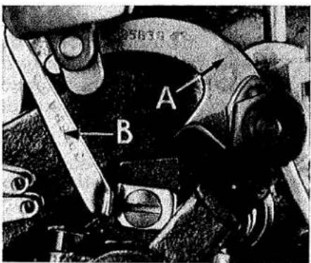
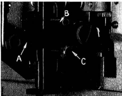
Sufficient presser foot pressure to feed work uniformly should be maintained. Should it be necessary to increase or decrease amount of pressure on presser foot, loosen lock nut (A, Fig. 2) and turn adjusting screw (B). Adjusting screw has a right hand thread so tightening increases
text_image
Labeled mechanical device diagram with components A, B, C, D and a base blockFig. 2
pressure, loosening decreases pressure. When pressure adjusting screw (B) has been properly set, tighten lock nut (A). With presser foot resting on throat plate, position locking nut (C) so that its under surface is approximately 1/32 to 1/16 inch (.79 to 1.59 mm) from the top surface of adjusting screw (B). Set cap (D) against locking nut (C).
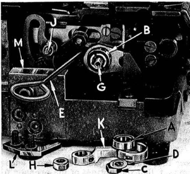
text_image
D Tension Nut E Tension Spring Ferrule F Tension Spring G Tension Post. H Spring Shield J Tension Discs K Tension Post Slot L Tension Disc Felt B Thread Eyelet To Upper Looper To Lower Looper A Cone Support 70° 50° 35° C Tension Thread Guide M Front Thread Guide N Upper Looper Thread Eyelet P Auxiliary Looper Thread Eyelet R Lower Looper Thread Eyelet S Fabric Guard Bracket T Frame Looper Thread Guide U Presser Arm AG Presser Foot Release Bushing AF Looper Thread Pull-off AE Needle Thread Cam Pull-off AD Needle Thread Eyelet AC Top Cover Needle Thread Eyelet AA Upper Looper Thread Tube Assembly X Needle W Upper Looper V Lower LooperFig. 1
504 STITCH FOR STYLES 39500 QS, QT, RT, TJ, TM and TT

text_image
D Tension Nut E Tension Spring Ferrule F Tension Spring G Tension Post H Spring Shield J Tension Discs K Tension Post Slot L Tension Disc Felt B Thread Eyelet To Upper Looper To Lower Looper To Left Needle To Right Needle A Cone Support 65° 45° 35° 30° C Tension Thread Guide M Front Thread Guide N Upper Looper Thread Eyelet P Auxiliary Looper Thread Eyelet R Lower Looper Thread Eyelet S Fabric Guard Bracket T Frame Looper Thread Guide U Presser Arm AF Presser Foot Release Bushing AE Top Cover Needle Thread Eyelet AD Thread Tube Assembly X Needles W Upper Looper V Lower Looper 512 STITCH FOR STYLES 39500 RD and RL 514 STITCH FOR STYLE 39500 TK Fig. 1AFEED ECCENTRICS
Feed eccentrics used in Style 39500 QS machines have been selected to produce approximately 14 stitches per inch. It will be noted that the part number of main feed eccentric is No. 39540 B-14 while that of the differential feed eccentric is No. 39540 B-4. Minor numbers of the part symbol indicate approximately the number of stitches obtainable when using that eccentric. Unless otherwise specified, machine Style 39500 QS will be shipped with above combination of eccentrics. Refer to exploded views in catalog for eccentrics furnished on other styles of machines.
Generally speaking, the main (right hand) feed eccentric determines the number of stitches produced; the differential (left hand) feed eccentric is selected so as to give the proper differential or gathering action.
Following stitch number feed eccentrics are available under No. 39540 B-4, 5, 6, 7, 8, 9, 10, 11, 12, 13, 14, 15, 16, 18, 20, 22, 24, 26, 28, 30, 32, 34, 36, 40. Only two eccentrics are supplied with each machine. Additional eccentrics may be ordered separately. To order an eccentric, use No. 39540 B with a minor number suffixed to indicate number of stitches desired. Example: "39540 B-14".
ASSEMBLING AND ADJUSTING SEWING PARTS
Before assembling and adjusting sewing parts, remove cloth plate, fabric guard, chip guard, upper knife assembly, lower knife holder assembly, then follow this suggested sequence:
text_image
D A C BFig. 3
CLOTH PLATE REMOVAL AND ASSEMBLY
CAUTION: When removing the cloth plate (A, Fig. 3) loosen the cloth plate stud locking screw (B) and lift up cloth plate with the cloth plate stud (C) and cloth plate screw (D), assembled.
In assembly, the cloth plate screw and the cloth plate stud are tightened to the point of removing all play and yet turn in cloth-plate. The cloth plate is then assembled to the machine with the flat and "V" slot of the cloth plate stud (C) towards the rear. Stud locking screw (B) is tightened securely which collapses the body of the stud to the screw (D) so that only the cloth plate will turn when opening or closing.
SETTING THE NEEDLE
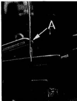
With throat plate assembled in position, needle should center in the front end of needle slot. When needle is at high position, needle point should be set 1/2 inch (12.70 mm) above throat plate (A, Fig. 4) for Styles 39500 QS, QT, RT, TM & TT; 15/32 inch (11.91 mm) for Styles 39500 RD, RL and TJ. For Style 39500 TK the setting should be 31/64 inch (12.30 mm). To align
needle or set the height above the throat plate, move needle driving arm (B, Fig. 4) by loosening clamp screw (C). After needle has been set properly, tighten clamp screw and remove throat plate.
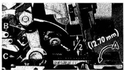
text_image
B C 1/2" (12.70 mm) AFig. 4
SETTING THE NEEDLE (Continued)
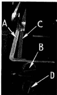
If needle thread cam pull-off (A, Fig. 5) overlaps looper thread pull-off (B), separate by moving looper thread pull-off back. When retightening looper pull-off screw, be sure to take up end play in needle driving arm.
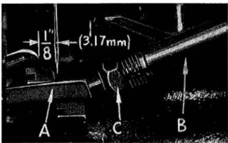
At this point, insert lower looper (A, Fig. 6) into bar (B). With lower looper at left end of its stroke, set looper point 1/8 inch (3.17 mm) from center of needle (Fig. 6), using looper gauge No. 21225-1/8, on Styles 39500 QS, QT, RT, TJ, TM & TT. On Styles 39500 RD, RL and TK, with lower looper at left end of its stroke, set looper point 1/16 inch (1.59 mm) to the left of center line of left needle, using looper gauge No. 21225-1/16. Do not have lower looper deflecting needle or needles. Tighten nut (C). Now assemble differential (front) feed dog.
text_image
A BFig. 5
SETTING THE REAR NEEDLE GUARD
Set rear needle guard (A, Fig. 7) as high as possible, without interfering with either lower looper or movement of lower knife holder, but still in position to deflect needle or needles forward .002-.004 inch (.051-.102 mm). Screw (B) is used to set rear needle guard. Make sure there is no interference between rear needle guard and lower looper.
SETTING THE LOWER LOOPER
text_image
1/8 (3.17mm) A C BFig. 6
Now finish lower looper adjustment. As lower looper moves to the right, its point should be set into the needle scarf (A, Fig. 8) until the needle springs forward from rear needle guard surface another .002-.004 inch (.051-.102 mm). Tighten nut (C, Fig. 6) securely.
natural_image
Black-and-white photo of a mechanical component with an arrow pointing to a section (no visible text or symbols)Fig. 8
SETTING THE FRONT NEEDLE GUARD
Assemble front needle guard (C, Fig. 7). When lower looper is springing needle off rear needle guard, set front needle guard as close as possible to needle without touching. Screw (D) is used to adjust and set front needle guard. After this setting make sure there is no interference between needle guards and differential feed dog.
SETTING THE UPPER LOOPER
text_image
A C B DFig. 7
Fig. 8 Insert upper looper (A, Fig. 9) in its holder. Screw (B), holds upper looper in its holder, and permits it to be pushed in or out or turned around its shank. Insert upper looper holder into upper looper shaft, if it is not already in place. Screw (C), on clamp holds the upper looper holder in the shaft. Locate upper looper in its holder so that the shank extends 1/16 to 3/32 inch (1.59 to 2.38 mm) beyond holder (Fig. 9) for Styles 39500 QS, QT, RD, RL, RT, TJ, TM and TT. For Style 39500 TK the shank should extend 1/8 inch (3.17 mm) beyond holder.
SETTING THE UPPER LOOPER (Continued)
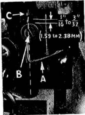
text_image
C 1" 16 to 3" 32 (1.59 to 2.38MM) B AFig. 9
When the upper looper is at the right end of its stroke, upper looper holder should be set to position upper looper shank approximately vertical on Styles 39500 QS, QT, RT, TJ, TM and TT (Fig. 9).
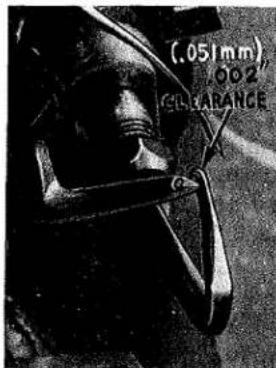
NOTE: OnStyles 39500 RD, RL and TK the upper looper holder should be set to position upper looper shank slightly back of vertical, when the upper looper is at right end of its stroke. Be sure, on all styles, there is a clearance between heel of looper and casting. By adjusting looper holder in or out of upper looper shaft and by turning the looper around its shank, set upper looper point to cross lower looper to the left of the lower looper eye with .002 to .004 inch (.051-.102 mm) clearance (Fig. 10).
As the upper looper moves toward the top of its stroke, the heel of the upper looper should pass behind the lower looper head with 1/64 to 1/32 inch (.40 to .79 mm) clearance.
Next, turn handwheel until looper is at the left end of its travel; check dimensions of upper looper point with respect to needle and throat plate (Fig. 11). If resetting is necessary, do it by moving the upper looper holder (A, Fig. 11). Figure 11 represents the dimensional setting for Styles 39500 QS, QT, RT, TM and TT.
NOTE: For Styles 39500 RD and RL, the dimensional settings are 1/8 inch (3.17 mm) to the left of right needle centerline and 17/32 inch (13.49 mm). For Style 39500 TJ the settings are 9/64 inch (3.57 mm) and 15/32 inch (11.91 mm) and for Style 39500 TK the settings are 3/16 inch (4.76 mm) and 39/64 inch (15.48 mm). For example,

text_image
(357mm) 9" 64 A 1/2" (2.70mm)Fig. 11
dimension 1/2 inch (12.70 mm) is increased by turning upper looper holder counterclockwise looking from left end of machine; dimension 9/64 inch (3.57 mm) is increased by pulling upper looper holder to the left, out of upper looper shaft. After these changes are made, it may be necessary to turn upper looper around its shank slightly to maintain the condition shown in Figure 10.
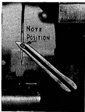
When the correct setting is obtained, it can be checked quickly as follows: As upper looper is moving to the right, when upper looper eye centers on the needle, the eyes of the upper looper and needle should align exactly (Fig. 12).
Check setting to avoid interference between upper looper and needle on needle downstroke. If needle rubs the back of upper looper, pull looper out of its holder slightly and rotate looper a short distance counterclockwise, looking from left end of machine. Reset to maintain dimensions of Figs. 10, 11, 12.
SETTING THE FEED DOGS
Now assemble differential (front) feed dog (A, Fig. 13) if not already on machine. Assemble main (back) feed dog (B) and set both feeds so the top surfaces of the teeth all lie in the same plane. This can be checked by sighting across the teeth with a straight edge. Now assemble throat plate. Feed dogs should now be leveled with throatplate surface by rotating feed tilting adjusting pin (C). This pin raises or lowers the back end of both feed bars at the same time.
text_image
(.051mm) .002" CLEARANCEFig. 10
text_image
Note PositionFig. 12
SETTING THE FEED DOGS (Continued)
The feed dogs should be set level at the time teeth first appear above the throat plate. Screw (D) locks feed tilting adjusting pin in place. Now set feed dogs so that teeth rise about 3/64 inch (1.19 mm) above throat plate. The differential feed may be set slightly higher if desired. On Style 39500 TK with the feed dogs at their highest point of travel the top of the teeth on the main and differential feed dogs (A, B) should be the depth of a full tooth above the throat plate. The chaining feed dog is made as an integral part of the main feed dog.
SETTING THE LOWER KNIFE
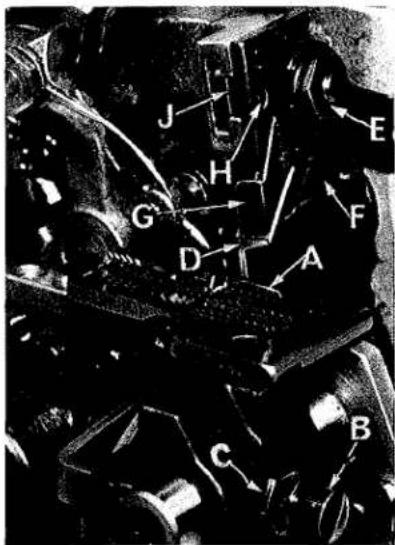
Replace lower knife holder assembly. Lower knife (A, Fig. 14) should be set with cutting edge flush with throat plate surface. Adjustments are made with hexagonal head screw which holds lower knife. Lower knife is spring pressed against upper knife, so no lateral adjustment is necessary when width of trim is changed.
Lower knife may be secured in any position by tightening screw (B) and locking nut (C) against support bracket. Because screw (B) also serves as latch pin for the cloth plate latch spring, it should always be locked with nut (C) even when screw is not tightened against lower knife holder.

text_image
C D B AFig. 13
text_image
J H G D A F E C BFig. 14
SETTING THE UPPER KNIFE
Replace upper knife assembly. Clamp upper knife (D, Fig. 14) in position, setting nut (E) to hold clamp (F) in its most clockwise position against upper knife. Upper knife chain guard (G) should be positioned so that the guarding section is approximately 1/64 inch (.40 mm) behind the cutting edge and in contact with the top surface of the upper knife.
At the bottom of its stroke, front cutting edge of upper knife should extend not less than 1/64 inch (.40 mm) below cutting edge of lower knife.
After upper knife has been set for proper width of trim, screw (H) must be tightened to lock the upper knife holding block (J) in place. This will simplify re-setting when upper knife is replaced.
For Style 39500 TJ, replace upper knife assembly. Clamp upper knife in position, setting the Allen screw located on the right side to hold the clamp against the upper knife. At the bottom of its stroke, the front cutting edge of the upper knife should extend not less than 1/64 inch (.40 mm) below the cutting edge of the lower knife.
After the upper knife has been set for the proper width of trim, the upper knife holding block should be locked in place using the screw at the front of the holding block.
SETTING THE STITCH LENGTH
Length of stitch is determined by the combination of feed eccentricities used. Outer (left) eccentric (A, Fig. 15) actuates differential (front) feed dog; while the inner (right) eccentric (B) actuates the main (rear) feed dog.
text_image
Labeled mechanical assembly diagram with components A through M and a central valve GFig. 15
In assembling feed eccentrics, be sure hubs are facing each other. Be careful not to damage shaft or key. Use nut (C) and washer (D) and tighten securely.
To change feed eccentric, remove thrust finger (L) from its seat on the main frame (M). Remove nut (C) and washer (D) from end of shaft (G). Remove nut (H) from stud (J). Link (K) and eccentric (A) will now slip off.
Using hooked eccentric extractor (E), supplied with machine, reach behind eccentric (B) as shown and withdraw eccentric. It may be necessary to move handwheel back and forth slightly during extraction.
SETTING THE DIFFERENTIAL RATIO
Differential feed action is obtainable thru the use of one micrometer adjusting screw on Styles 39500 TJ and TK and two micrometer adjusting screws on Styles 39500 QS, QT, RD, RL, RT, TM and TT.
The position of the differential control lever (A, Fig. 16) is governed by an upper and a lower stop. The amount of lever movement between these two stops determines the feed action.
On Styles 39500 TJ and TK rotating the one adjusting thumbscrew (located near the tension post assembly) in a clockwise direction increases the differential action by moving the upper stop (B) down, a counterclockwise turn acts in a reverse manner. Now set the lower stop screw (C) so as to obtain the required intermittent differential feed. On Styles 39500 TJ and TK the two stops may be reversed to meet a specific sewing requirement.
text_image
A B CFig. 16
NOTE: After lower stop screw has been set, push differential control lever down, hold in this position and turn handwheel in operating direction to be sure the differential feed dog does not strike the throat plate.
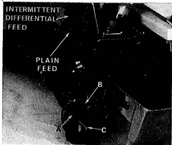
On Styles 39500 QS, QT, RD, RL, RT, TM and TT the differential feed action is also controlled by the movement of the differential control lever (A, Fig. 16A) between an upper (B) and a lower stop (C), but on these machines both stops are moved by an adjusting thumbscrew rod (Fig. 16A).
SETTING THE DIFFERENTIAL RATIO (Continued)
To set the amount of differential or plain feed, turn the plain feed control adjusting rod, it is the larger knurled head screw located on the bed in back of the tension post assembly. Turning this rod clockwise decreases the amount of differential and turning it counterclockwise increases the amount of differential.
The amount of intermittent differential feed is set by turning the differential feed control adjusting rod, it is the smaller knurled head screw located just above the plain feed control adjusting rod. Turning this screw clockwise lowers the stop and thus increases the amount of differential, when the differential feed control lever is actuated. Turning this screw counterclockwise acts the reverse.
SETTING THE PRESSER FOOT
Assemble the presser foot to presser arm. With needle in high position, swing presser arm into sewing position and set the presser foot to align needle holes (front and back) and flat on throat plate.
text_image
INTERMITTENT DIFFERENTIAL FEED PLAIN FEED A B CFig. 16A
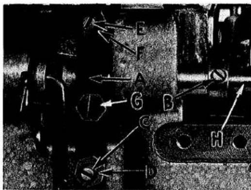
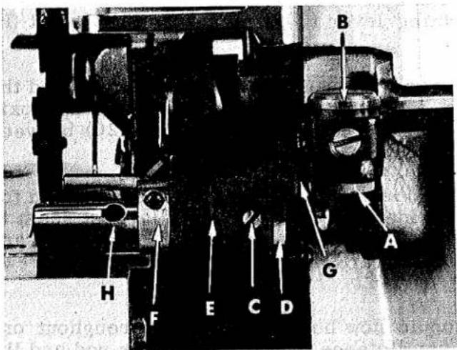
The front edge of needle hole in presser foot must be aligned with front edge of needle hole in throat plate. It is also important that the bottom of the presser foot be flat on the throat plate. If necessary, presser foot can be realigned with throat plate slots by shifting the foot lifter lever shaft (H, Fig. 17). To move the shaft, loosen collar screws (B, Fig. 17) and clamp screw (G) and then shift the foot lifter lever shaft to the left or right as required. Retighten collar screws and clamp screw.
text_image
Technical diagram with labeled components and directional arrows, likely from an engineering or mechanical contextFig. 17
The foot lifter lever arm (A, Fig. 17) and the collar (B) secure the shaft. Be sure the presser arm does not bind or rise when presser foot release bushing is unlocked.
Adjust lifter lever stop screw (C) so that presser foot can be raised no higher than upper looper will permit; then lock the nut (D). There should be from 1/16 to 1/8 inch (1.59 to 3.17 mm) free motion of foot lifter lever before the presser foot begins to rise. This adjustment should be made with screw (E) and locked with nut (F). Re-assemble the chip guard, fabric guard and cloth plate. To assemble chip guard, turn handwheel until upper knife assembly re-
aches its highest position.
SETTING THE PRESSER FOOT HOLD DOWN PLATE
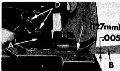
Styles 39500 QT, RD, RL, RT, TK, TM and TT are equipped with a presser foot hold down plate (A, Fig. 18). The purpose of this plate is to hold down the rear of the presser foot and when set correctly it will help produce a more flat pucker free seam. An approximate setting is shown in Fig. 18. Set the machine with the feed dogs below the throat plate and insert a .005
inch (.127 mm) shim (B) under the front portion of presser foot (C). Loosen screws (D) which hold the hold down plate in position and move the plate down until it rests firmly against the presser foot. Tighten the two screws and remove the shim.
text_image
A D (127mm) .005 BFig. 18
SETTING THE PRESSER FOOT HOLD DOWN PLATE (Continued)
NOTE: Always be sure the feed dogs are below surface of throat plate when making this setting.
SETTING THE PRESSURE PLATE ASSEMBLY
Styles 39500 QT, RD, RL, RT, TM and TT are equipped with an auxiliary pressure plate assembly (Fig. 19) which operates in conjunction with the presser foot. Check the operation of this assembly as follows:
text_image
B A G H F E C DFig. 19
-
Swing the pressure plate assembly in and out of its operating position and check to assure that it hinges freely on its pivot. If not, loosen lock nut (A, Fig. 19) and adjust shoulder screw (B) for smooth operation.
-
Loosen set screw (C, Fig. 19) and turn the shaft collar (D) counterclockwise (viewed from the left side of machine) using the spanner wrench provided, so there is some tension on the tension spring located in the shaft bracket (E) and the pressure plate (A, Fig. 20) is forced down slightly.
-
Adjust tension spring, located in the mounting bracket (B, Fig. 20) with inner screw, after removing outer screw (C). Spring should be tight enough to allow assembly to snap into place and still allow the mechanism to swing out easily. Lock inner screw with outer screw (C).

text_image
FINEST QUALITY .005-.010 (.127 to .254mm) A B C D E F GFig. 20
- With the feed dogs down, look horizontally between the pressure plate and the throat plate from the front of the machine to assure that the pressure plate lies flat on the throat plate. If not, loosen the two screws (D, Fig. 20) which hold the pressure plate (A) and adjust flat to the throat plate.
SETTING THE PRESSURE PLATE ASSEMBLY (Continued)
- Raise or lower the mounting bracket (B, Fig. 20) by loosening screws (E) so that, from the side, the pressure plate is parallel and flat on the throat plate. Retighten screws (E).
- Adjust screw (F, Fig. 20) so that the front edge of the pressure plate is square to the feed dog teeth. Lock with screw (G).
- Center pressure plate over the feed dogs by loosening the screws in the actuating collar (F, Fig. 19) and the operating lever (G), and then adjust shaft (H) laterally as required.
- When retightening operating lever screw make sure that the feed dogs and the pressure plate are down, then tighten operating lever screw leaving approximately .005 to .010 inch (.127 to .254 mm) clearance (See Fig. 20) between operating lever and shaft bracket (E, Fig. 19).
- With feed dogs up, check from the left side to see if the clearance between the pressure plate and the presser foot is wide enough to allow the largest seam to pass. If not, adjustment can be made by loosening screws (E, Fig. 20) and moving the mounting bracket (B) straight toward the operator. Retighten screws (E). Recheck Step 4.
- The actuating collar (F, Fig. 19) should now be set so that, throughout one revolution of the machine, the minimum distance between the lifter rod and the presser foot is 1/32 inch (.79 mm). The lifter rod should be set to clear the tip of the presser foot if it is important that the shirring mechanism can be swung away without moving the presser foot away first.
- Loosen set screw (C, Fig. 19) for final adjustment of pressure plate tension spring. Turn shaft collar (D) with spanner wrench until desired tension is acquired to obtain a uniform shirr. Retighten set screw (C).
STARTING TO OPERATE
Be sure machine is threaded according to threading diagram (Fig. 1 or 1A). With thread tension light, set looper thread eyelets (N and R) about horizontal and in the middle of their front to back locations. Operate machine slowly, without presser foot in place, to make sure the chain forms and moves off the tongue freely. Swing presser foot into position, insert material and sew slowly.
NEEDLE THREAD CONTROL
While sewing on material, check needle thread control as follows: Usually all needle thread is drawn on needle downstroke. At top of needle stroke, thread should be just tight enough to feed chain off stitch tongue. Stitch tends to pull down slightly if excessive thread is pulled on the up stroke. With needle at bottom of stroke, position needle thread eyelet (AD, Fig. 1 or 1A) so that needle thread cam pull-off (AE) just contacts needle thread or threads.
LOWER LOOPER THREAD CONTROL
With material under presser foot, set lower looper thread eyelet (R, Fig. 1 or 1A) back far enough so thread is a little slack when looper thread pull-off (AF) reaches its most rearward position. Looper thread pull-off (AF) is set about 1/8 inch (3.17 mm) distance behind needle thread cam pull-off (AE). Frame looper thread guide (T) should be set with its eyelet approximately 1/8 inch (3.17 mm) right of lower looper (V) heel eyelet at the time lower looper is at extreme left end of its travel.
LOWER LOOPER THREAD CONTROL (Continued)
While sewing on material, check drawing off of looper thread as follows: A portion of lower looper thread should be drawn through the tension before lower looper thread comes off upper looper. To increase amount of thread drawn through the tension while lower looper thread is on upper looper, move lower looper thread eyelet (R) down, keeping the same amount of pull-off action.
UPPER LOOPER THREAD CONTROL
Before proceeding to adjust upper looper thread eyelet (N, Fig. 1 or 1A) balance all three or four tensions to give a normal appearing stitch. Moderate change in these tensions will not markedly affect the purl.
During needle down stroke, forward stroke of looper thread pull-off (AF) will draw upper looper thread through the tension. When normal amount of looper thread is drawn, upper looper thread will have almost all slack taken up as looper thread pull-off reaches its most rearward position.
POSITIONING THE PURL
To move the purl more under the edge, both looper thread eyelets (N and R, Fig. 1 or 1A) should be raised keeping the same amount of pull-off. Usually it is better to have slightly more pull-off on upper thread than on lower thread.
If it becomes necessary to move looper thread pull-off (AF), be sure to take up all end play in needle drive shaft before tightening. If upper looper is located so that it is higher over throat plate than recommended in (Fig. 11), the purl will tend to form near top edge. If upper looper is too low, the purl will form nearer bottom edge.
THREAD TENSIONS
The needle thread tension required is a function of needle thread and material being sewn. In general, lower looper thread tension should be set as high as possible without causing needle thread to be pulled down. Upper looper thread tension should be increased as long as the elasticity of the chain increases, or until the purl is pulled too far over the top.

text_image
Technical diagram of an electric motor with labeled components and rotation direction indicatorFig. 21
TO REMOVE CRANKSHAFT
Crankshaft can be withdrawn easier if these steps are followed:
- Drain oil by removing plug screw located on back of machine near bottom edge of base.
- Remove top and bottom covers of machine.
- Remove feed eccentric nut (A, Fig. 21) and washer (B), and, with the aid of the eccentric extractor, slip off the eccentrics (C).
- Remove key (D).
- Remove three counterweights (E). Identify these counterweights so that they will be re-assembled in the proper places.
-
Remove screw (F) which holds crankshaft split bearing. This screw is reached through bottom of bed casting.
-
Remove caps of bearings on crankshaft at points G, H and J. When re-assembling bearing caps make sure they are in their original position. Trade marks are stamped on both halves of the caps and both trade marks should be on the same side of the bearings. Also, screws should be re-assembled in the same holes from which they were removed.
-
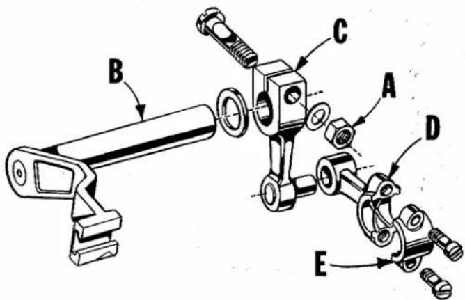
Loosen clamp nut (A, Fig. 22) which holds upper knife driving arm (B). Access to clamp nut is through top cover. Draw driving arm to the left until upper knife driving lever (C) and connecting
text_image
Technical diagram of a mechanical assembly with labeled parts A, B, C, D, and EFig. 22
rod (D) drop, allowing removal of bearing cap (E). This is at bearing point (K, Fig. 21) on crank shaft. Observe same precautions when re-assembling cap as described in 7 above.
-
Remove screw (L, Fig. 21) which holds inner right crankshaft bearing. This screw is reached through bottom of bed casting.
-
Loosen two screws (M) in fan collar; remove both halves of cooling fan.
-
Remove screw (N); take off pulley cap (P).
-
Loosen two screws (R); remove pulley (S).
-
Remove three screws (T); take off bearing retaining plate (U); also, spacer collars (V) and (W) may be removed at this time.
-
Crankshaft may now be removed.
-
If necessary to replace ball bearing (X), it should be pressed off shaft on an arbor press. In replacing bearing it must be pressed on carefully until it seats against ground thrust washer (Y).
-
Carefully observing reverse of the foregoing operations should simplify re-assembly of crankshaft. Checking exploded view drawings for location of various parts and constant testing for binds during re-assembly will also prove helpful.
-
Before re-assembling, thoroughly clean and dry top and bottom covers and gaskets. Before re-assembling bottom cover make sure that spring pressed oil wick which lubricates left crankshaft bearing is inserted in hole in casting and that it contacts shaft. The wick stands vertically on its spring against bottom cover. Coat oil drain plug with a sealing compound before re-assembling to prevent oil leakage. No. 1 Crane Lead Seal is recommended.
ORDERING REPAIR PARTS
ILLUSTRATIONS
This catalog has been arranged to simplify ordering repair parts. Exploded views of various sections of the mechanism are shown so that the parts may be seen in their actual position in the machine. On the page opposite the illustration will be found a listing of the parts with their part numbers, description and the number of pieces required in the particular view being shown.
Numbers in the first column are reference numbers only, and merely indicate the position of that part in the illustration. Reference number should never be used in ordering parts. Always use the part number listed in the second column.
Component parts of sub-assemblies which can be furnished for repairs are indicated by indenting their descriptions under the description of the main sub-assembly. Example:
| 25 | 29477 KE | Crankshaft and Needle Driving Arm Crank Assembly---- | 1 |
| 26 | 29477 MC | Needle Driving Arm Crank and Connecting Rod Assembly---- | 1 |
| 27 | 22768 C | Screw, for needle driving arm connecting rod pin---- | 1 |
| 28 | 22596 H | Screw, for needle driving arm crank---- | 1 |
| 29 | 22587 M | Screw, for needle driving arm connecting rod--- | 2 |
| 30 | 51-228 Blk. | Vent Plug---- | 1 |
| 31 | 39541 A | Feed Driving Eccentric Key---- | 1 |
| 32 | 30-106 Blk. | Wood Plug---- | 1 |
| 33 | CO67 E | Cork Plug---- | 1 |
| 34 | 40-46 | Washer---- | 1 |
| 35 | 258 | Nut---- | 1 |
It will be noted in the above example that the needle driving arm crank, needle bearing or connecting rod are not listed. The reason is that replacement of these parts individually is not recommended, so the complete sub-assembly should be ordered.
Where the parts for all the styles covered in this catalog are not the same, the difference will be shown in the illustration or mentioned in the descriptions. When a part is used in all machines covered by this catalog no machine style will be mentioned.
At the back of the book will be found a numerical index of all the parts shown in this book. This will facilitate locating the illustration and description when only the part number is known.
IDENTIFYING PARTS
Where the construction permits, each part is stamped with its part number. On some of the smaller parts, and on those where construction does not permit, an identification letter is stamped in to distinguish the part from similar ones.
PART NUMBERS REPRESENT THE SAME PART, REGARDLESS OF CATALOG IN WHICH THEY APPEAR.
USE GENUINE NEEDLES AND REPAIR PARTS
Success in the operation of these machines can be secured only with genuine UNION SPECIAL Needles and Repair Parts as furnished by the Union Special Corporation, its subsidiaries and authorized distributors. They are designed according to the most scientific principles, and are made with utmost precision. Maximum efficiency and durability are assured.
Genuine needles are packaged with labels marked Union Special®. Genuine repair parts are stamped with the Union Special trademark, U S Emblem. Each trademark is your guarantee of the highest quality in materials and workmanship.
TERMS
Prices are net cash and subject to change without notice. All shipments are forwarded f.o.b. shipping point. Parcel post shipments are insured unless otherwise directed. A charge is made to cover postage and insurance.
TORQUE REQUIREMENTS
Torque (measured in inch-pounds) is a rotating force (in pounds) applied through a distance by a lever (in inches or feet). This is accomplished by a wrench, screw driver, etc. Many of these devices are available, which when set at the proper amount of torque will tighten the part to the correct amount and no tighter.
All straps and eccentrics should be tightened to 19-21 inch-pounds (22-24 cm/kg) unless otherwise noted. All other nuts, bolts, screws, etc., should be tightened by hand as tightly as possible, unless otherwise noted.
The screws requiring a specific torque, will be indicated on the picture plates.

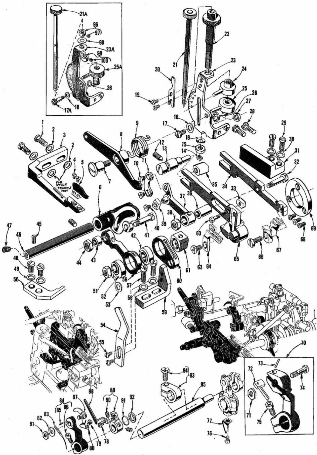
text_image
Exploded view diagram of a device with numbered parts and exploded views, including labeled parts like 'Union Special' and assembly instructions.MAIN FRAME, PRESSER FOOT RELEASE PARTS MISCELLANEOUS COVERS AND PLATES
| Ref.No. | PartNo. | Description | AmRec |
| 1 | 39557 B | Presser Spring Plunger Cap Nut | 1 |
| 2 | 39557 E | Presser Spring Plunger Locking Nut | 1 |
| 3 | 39557 C | Presser Spring Plunger Adjusting Screw | 1 |
| 4 | 39557 F | Lock Nut, for adjusting screw | 1 |
| 5 | 39557 | Presser Spring | 1 |
| 6 | 39557 A | Presser Spring Plunger | 1 |
| 7 | 39563 F | Top Cover Needle Thread Eyelet, for all Styles except 39500 RD, RL, TK | 1 |
| 7A | 39563 W | Top Cover Needle Thread Eyelet, for Styles 39500 RD, RL, TK | 1 |
| 8 | 22569 B | Screw, for top cover needle thread eyelet | 2 |
| 9 | 39556 A | Presser Foot Release Bushing | 1 |
| 10 | 39582 AD | Top Cover, for all Styles except 39500 RD, RL, TK | 1 |
| - | 39582 AK | Top Cover, for Styles 39500 RD, RL, TK | 1 |
| 11 | 39582 AF | Oil Filler Cover | 1 |
| 12 | 39582 V | Spring | 1 |
| 13 | 39582 AG | Hinge Bracket | 1 |
| 14 | 51-103 Blk. | Hinge Pin | 1 |
| 15 | 39582 W | Oil Guard | 1 |
| 16 | 22562 A | Screw, for hinge bracket | 1 |
| 17 | 39582 AE | Top Cover Gasket | 1 |
| 18 | 22541 | Screw, for top cover | 8 |
| 19 | 667 D-8 | Dowel Pin | 2 |
| 20 | 22565 S | Spot Screw, for upper looper drive lever shaft | 1 |
| 21 | 22569 D | Screw, for oil collector plate | 1 |
| 22 | 22565 | Set Screw, for upper looper thread tube assembly and for upper looper drive lever shaft | 2 |
| 23 | 39594 R | Oil Collector Plate | 1 |
| 24 | 22571 E | Magnetic Oil Drain Plug Screw | 1 |
| 25 | 29477 GW | Upper Looper Thread Tube Assembly, for all Styles except 39500 TK | 1 |
| 25A | 29477 HJ | Upper Looper Thread Tube Assembly, for Style 39500 TK | 1 |
| 26 | 39568 G | Thread Tube, for No. 29477 GW | 1 |
| 26A | 39568 P | Thread Tube, for No. 29477 HJ | 1 |
| 27 | 39568 J | Thread Tube Tension Spring | 1 |
| 28 | 22743 | Set Screw, for thread tube tension spring | 1 |
| 29 | 39501 K | Cloth Plate Stud | 1 |
| 30 | 22569 | Screw, for cloth plate stud | 1 |
| 31 | 39535 H | Feed Bar Guide | 1 |
| 32 | 22569 C | Screw, for feed bar guide | 1 |
| 33 | 22565 F | Screw, for feed adjusting pin | 1 |
| 34 | 22569 B | Screw, for oil filter screen and strainer | 2 |
| 35 | 39594 G | Oil Filter Screen | 1 |
| 36 | 39594 H | Oil Strainer, felt | 1 |
| 37 | 39578 K | Cloth Plate Fabric Guard | 1 |
| 38 | 138 | Screw, for cloth plate fabric guard | 2 |
| 39 | 22657 D-12 | Screw, for cloth plate | 1 |
| 40 | 39501 DC | Cloth Plate, for semi or fully submerged installation on all Styles except 39500 TJ | 1 |
| 40A | 39501 EC | Cloth Plate, for non submerged installation on all Styles except 39500 TJ | 1 |
| 40B | 39501 EB | Cloth Plate, for non submerged installation on Style 39500 TJ | 1 |
| 40C | 39501 DB | Cloth Plate, for semi or fully submerged installation on Style 39500 TJ | 1 |
| 41 | 39599 | Tape Guide, for Styles 39500 TJ | 1 |
| 42 | 69 H | Washer, for tape guide | 2 |
| 43 | 22569 | Screw, for tape guide | 2 |
| 44 | 22569 D | Screw, for chip guard | 2 |
| 45 | 39578 W | Chip Guard, for all Styles except 39500 TJ | 1 |
| 39578 T | Chip Guard, for Style 39500 TJ | 1 | |
| 46 | 22569 K | Screw, for oil sight gauge | 1 |
| 47 | 22894 AE | Screw, for lower looper bar driving lever shaft | 2 |
| 48 | 39593 H | Oil Sight Gauge | 1 |
| 49 | 660-243 | Oil Gauge Seal Ring | 1 |
| 50 | 39582 F | Bottom Cover Extension | 1 |
| 51 | 22653 D-4 | Screw, for bottom cover extension | 2 |
| 52 | 39582 BV | Air Duct, upper | 1 |
| 53 | 8372 A | Washer, for upper air duct | 2 |
| 54 | 22569 C | Screw, for upper air duct | 2 |
| 55 | 39582 BM | Base Plate | 1 |
| 56 | 22541 B | Screw, for base plate | 2 |
| 57 | 39595 | Isolator, for all Styles except 39500 TJ | 4 |
| 39595 | Isolator, for Style 39500 TJ | 2 | |
| 58 | 39582 BL | Air Duct, outer | 1 |
| 59 | 22569 D | Screw, for lower and outer air duct | 4 |
| 60 | 39582 BK | Air Duct, lower | 1 |
| 61 | 22586 R | Screw, for bottom cover | 1 |
| 62 | 22541 B | Screw, for bottom cover | 12 |
| 63 | 51295 B | Isolator, for Style 39500 TJ | 2 |
| 64 | 39532 A | Cloth Plate Latch Spring | 1 |
| 65 | 90 | Screw, for latch spring | 2 |
| 66 | 39582 BH | Bottom Cover Gasket | 1 |
| 67 | 39582 BG | Bottom Cover | 1 |
| 68 | 39593 C | Oil Gauge Float | 1 |
| 69 | 39593 D | Oil Gauge Indicator | 1 |
text_image
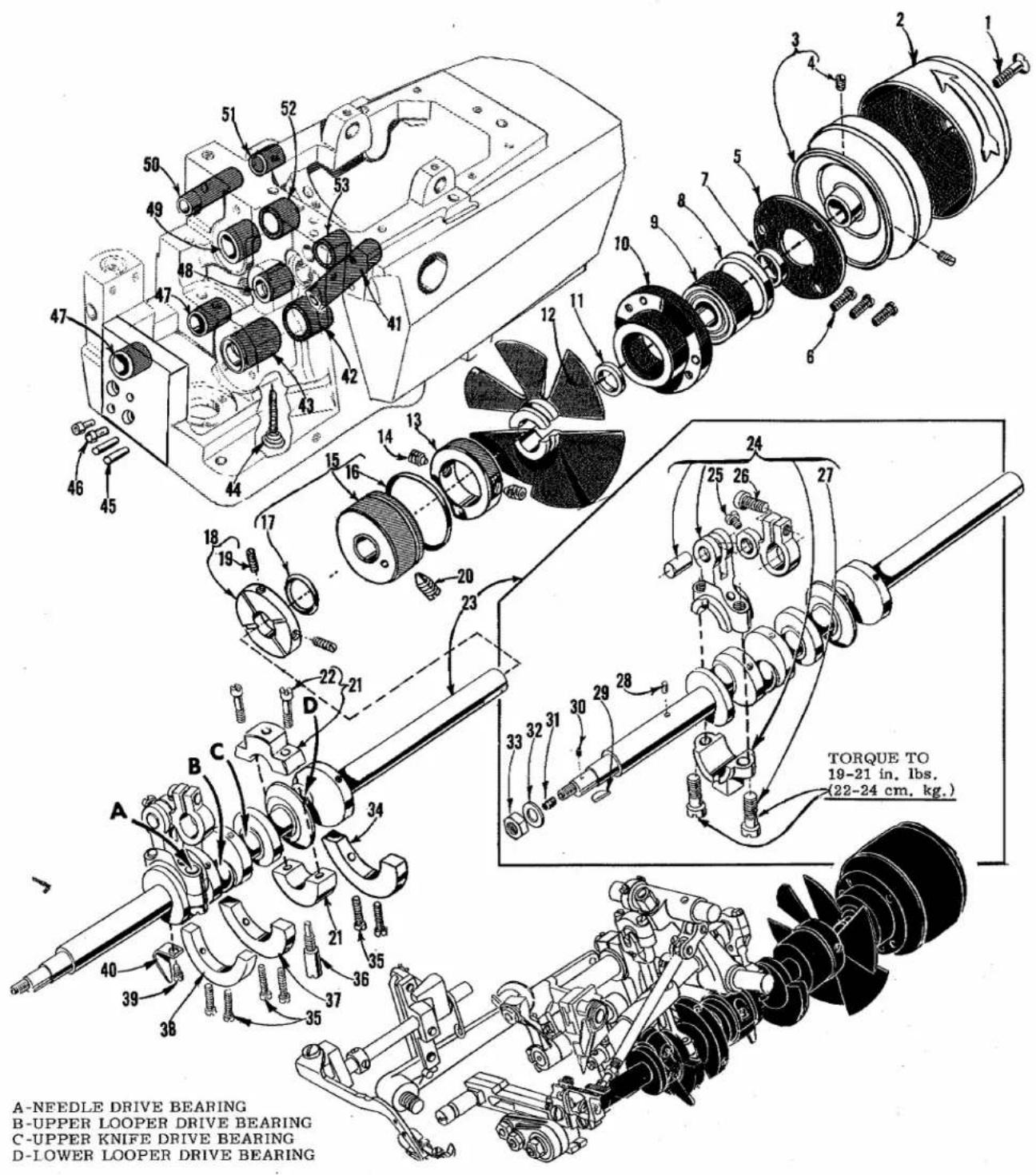
A-NFEDLE DRIVE BEARING B-UPPER LOOPER DRIVE BEARING C-UPPER KNIFE DRIVE BEARING D-Lower LOOPER DRIVE BEARING TORQUE TO 19-21 in. lbs. (22-24 cm. kg.)A-NEEDLE DRIVE BEARING
B-UPPER LOOPER DRIVE BEARING
C-UPPER KNIFE DRIVE BEARING
D-LOWER LOOPER DRIVE BEARING
CRANKSHAFT MECHANISM AND BUSHINGS
| Ref. No. | Part No. | Description | Amt. Req. |
| 1 | 22769 B | Screw, for pulley cap | 1 |
| 2 | 39521 D | Pulley Cap | 1 |
| 3 | 39521 G | Pulley | 1 |
| 4 | 95 | Screw, for pulley | 2 |
| 5 | 39590 H | Crankshaft Ball Bearing Retaining Plate | 1 |
| 6 | 22569 B | Screw, for crankshaft ball bearing retaining plate | 3 |
| 7 | 39590 S | Spacer Collar | 1 |
| 8 | 39590 R | Ball Bearing Stop Collar | 1 |
| 9 | 660-268 | Ball Bearing | 1 |
| 10 | 39590 G | Crankshaft Ball Bearing Housing | 1 |
| 11 | 39590 J | Thrust Washer | 1 |
| 12 | 39591 L | Crank Chamber Cooling Fan | 1 |
| 13 | 39591 H | Crank Chamber Cooling Fan Collar | 1 |
| 14 | 22894 D | Screw, for crank chamber cooling fan collar | 2 |
| 15 | 39590 X Y | Crankshaft Bearing, inner right per C.R 23716 7/30/82 | 1 |
| 16 | 660-443 | "O" Ring | 1 |
| 17 | 660-204 | "O" Ring | 1 |
| 18 | 39590 P | Oil Slinger Collar | 1 |
| 19 | 77 Q | Screw, for oil slinger collar | 1 |
| 20 | 22565 F | Screw, for crankshaft bearing, inner right | 1 |
| 21 | 39590 D | Crankshaft Split Bearing | 1 |
| 22 | 97 A | Screw, for crankshaft split bearing | 2 |
| 23 | 29477 KE | Crankshaft and Needle Driving Arm Crank Assembly | 1 |
| 24 | 29477 MC | Needle Driving Arm Crank and Connection Rod Assembly | 1 |
| 25 | 22768 C | Screw, for needle driving arm connecting rod pin | 1 |
| 26 | 22596 H | Screw, for needle driving arm crank | 1 |
| 27 | 22587 M | Screw, for needle driving arm connecting rod | 2 |
| 28 | 51-228 Blk. | Vent Plug | 1 |
| 29 | 39541 A | Feed Driving Eccentric Key | 1 |
| 30 | 30-106 Blk. | Wood Plug | 1 |
| 31 | CO67 E | Cork Plug | 1 |
| 32 | 40-46 | Washer | 1 |
| 33 | 258 | Nut | 1 |
| 34 | 39591 B | Crankshaft Counterweight, right | 1 |
| 35 | 22747 B | Screw, for crankshaft counterweights | 6 |
| 36 | 39590 N | Stud, for crankshaft split bearing | 1 |
| 37 | 39591 A | Crankshaft Counterweight, middle | 1 |
| 38 | 39591 K | Crankshaft Counterweight, left | 1 |
| 39 | 87 U | Screw, for oil splasher | 1 |
| 40 | 39594 N | Oil Splasher | 1 |
| 41 | 39544 L | Lower Looper Bar Bushing | 1 |
| 42 | 39590 T | Crankshaft Bearing, inner left | 1 |
| 43 | 39590 | Crankshaft Bearing, left | 1 |
| 44 | 666-94 | Oil Wick and Spring | 1 |
| 45 | 667 B-12 | Dowel Pin | 2 |
| 46 | 22653 B-12 | Socket Head Cap Screw | 2 |
| 47 | 43243 N | Differential Feed Rocker Shaft Bushing | 2 |
| 48 | 39552 U | Needle Driving Arm Crank Bushing, left | 1 |
| 49 | 39573 K | Upper Knife Driving Arm Bushing, left | 1 |
| 50 | 39555 E | Foot Lifter Shaft Bushing, left | 1 |
| 51 | 39555 N | Foot Lifter Shaft Bushing, right | 1 |
| 52 | 39573 AA | Upper Knife Driving Arm Bushing, right | 1 |
| 53 | 39552 P | Needle Driving Arm Crank Bushing, right | 1 |
text_image
Technical diagram of mechanical assembly with numbered parts and exploded view, including a detailed inset of a mechanical component.NEEDLE DRIVE AND FEED MECHANISM
| Ref.No. | PartNo. | Description | Amt.Req. |
| 1 | 22569 B | Screw, for fabric guard mounting bracket | 2 |
| *2 | 8372 A | Washer, for fabric guard mounting bracket | 2 |
| 3 | 39578 P | Fabric Guard Mounting Bracket | 1 |
| 4 | 87 | Screw, for fabric guard | 2 |
| 5 | 39578 M | Fabric Guard | 1 |
| 6 | 39536 L | Differential Feed Rocker | 1 |
| 7 | 22557 E | Screw, for differential feed control lever | 1 |
| 8 | 39536 U | Differential Feed Control Lever | 1 |
| 9 | 39536 V | Differential Feed Control Spring | 1 |
| 10 | 39536 Y | Screw, for control lever connecting link | 2 |
| 11 | 39536 W | Control Lever Connecting Link | 1 |
| 12 | 22565 F | Screw, for feed adjusting pin | 1 |
| 13 | 39535 E | Feed Adjusting Pin | 1 |
| 14 | 12934 A | Lock Nut, for differential feed control adjusting rod, for all Styles except 39500 TJ, TK | 1 |
| 15 | 39536 AH | Friction Nut, for differential feed control adjusting rod, for all Styles except 39500 TJ, TK | 1 |
| 16 | 39198 D | Spring Washer, for differential feed control adjusting rod, for all Styles except 39500 TJ, TK | 1 |
| 17 | 25 CC | Differential Feed Stop Screw, for all Styles except 39500 TJ, TK | 1 |
| 17A | 22728 A | Differential Feed Stop Screw, for Styles 39500 TJ, TK | 1 |
| 18 | 8372 A | Washer, for differential feed stop screw | 1 |
| 19 | 88 A | Screw, for ratchet stop spring, for all Styles except 39500 TJ, TK | 2 |
| 20 | 39636 E | Ratchet Stop Spring, for all Styles except 39500 TJ, TK | 1 |
| 21 | 39636 C | Differential Feed Control Adjusting Rod, for all Styles except 39500 TJ, TK | 1 |
| 21A | 39536 AB | Differential Feed Control Adjusting Rod, for Styles 39500 TJ, TK | 1 |
| 22 | 39636 A | Plain Feed Control Adjusting Rod, for all Styles except 39500 TJ, TK | 1 |
| 23 | 39636 | Differential Feed Control Mounting Bracket, for all Styles except 39500 TJ, TK | 1 |
| 23A | 39536 AJ | Differential Feed Control Mounting Bracket, for Styles 39500 TJ, TK | 1 |
| 24 | 39636 B | Plain Feed Control Adjustable Stop, for all Styles except 39500 TJ, TK | 1 |
| 25 | 39636 D | Differential Feed Control Adjustable Stop, for all Styles except 39500 TJ, TK | 1 |
| 25A | 39536 AC | Differential Feed Control Adjustable Stop, for Style 39500 TJ, TK | 1 |
| 26 | 43139 A | Nut, for stop screw | 1 |
| 27 | 18 | Nut, for differential feed control lever screw | 1 |
| 28 | 22824 B | Screw, for differential feed control mounting bracket | 2 |
| 29 | 22569 B | Screw, for feed bar guide, right | 2 |
| 30 | 53634 C | Washer, for feed bar guide, right | 2 |
| 31 | 39535 D | Feed Bar Guide, right | 1 |
| 32 | 39536 S | Differential Feed Bar Driving Stud | 1 |
| 33 | 39536 X | Differential Feed Bar Guide Block | 1 |
| 34 | 39534 B | Differential Feed Bar | 1 |
| 35 | 39535 J | Main and Differential Feed Bar Guide Block | 1 |
| 36 | 39536 R | Feed Bar Driving Connection Bushing | 1 |
| 37 | 39536 P | Differential Feed Drive Link | 1 |
| 38 | 39536 E | Nut, for differential feed bar driving stud | 1 |
| 39 | 39536 N-247 | Differential Feed Regulating Sliding Block, marked "A", .247 inch (6,274 mm) | 1 |
| - | 39536 N-248 | Differential Feed Regulating Sliding Block, marked "B", .248 inch (6,300 mm) | 1 |
| - | 39536 N-249 | Differential Feed Regulating Sliding Block, marked "C", .249 inch (6,325 mm) | 1 |
| 40 | 28 | Screw, for differential feed regulating sliding block | 1 |
| 41 | 39536 J | Differential Feed Drive Connecting Rod Stud | 1 |
| 42 | 39540 B-10 | Main Feed Driving Eccentric, for Style 39500 TJ | 1 |
| - | 39540 B-12 | Main Feed Driving Eccentric, for Style 39500 TK | 1 |
| - | 39540 B-14 | Main Feed Driving Eccentric, for Styles 39500 QS,QT,RD,RL,TM,TT - | 1 |
| - | 39540 B-16 | Main Feed Driving Eccentric, for Style 39500 RT | 1 |
| 43 | 39536 K | Feed Rocker Drive Connecting Bushing | 1 |
| 44 | 39536 E | Nut, for differential feed drive connecting rod stud | 1 |
| 45 | 22565 B | Screw, for differential feed rocker shaft | 2 |
| 46 | 39536 M | Differential Feed Rocker Shaft | 1 |
| 47 | CO67 F | Cork, for differential feed rocker shaft | 1 |
* Note: On Style 39500 TJ also use two No. 8372 A washers in front of No. 39578 P.

text_image
Technical diagram of mechanical assembly with numbered parts and exploded views, including disassembled components and assembly details.NEEDLE DRIVE AND FEED MECHANISM
| Ref.No. | PartNo. | Description | Amt.Req. |
| 1 thru 47 | See preceding page | ||
| 48 | 22569 C | Screw, for thrust finger | 2 |
| 49 | 53634 C | Washer, for thrust finger | 2 |
| 50 | 39536 H | Thrust Finger | 1 |
| 51 | 258 | Nut, for crankshaft | 1 |
| 52 | 39540 B-4 | Differential Feed Driving Eccentric, for Styles 39500 QS, QT,RD, TJ, TK, TT | 1 |
| - | 39540 B-6 | Differential Feed Driving Eccentric, for Style 39500 RT | 1 |
| - | 39540 C | Differential Feed Driving Eccentric, for Styles 39500 RL, TM | 1 |
| 53 | 40-46 | Washer, for crankshaft | 1 |
| 54 | 39580 J | Throat Plate Support | 1 |
| 55 | 22768 | Screw, for throat plate support | 2 |
| 56 | 39536 F | Differential Feed Drive Connecting Rod, for Styles 39500 QS,QT, RD, RT, TJ, TK, TT | 1 |
| - | 39536 G | Differential Feed Drive Connecting Rod, for Styles 39500 RL,TM | 1 |
| 57 | 22541 A | Screw, for feed bar guide, left | 2 |
| 58 | 53634 C | Washer, for feed bar guide, left | 2 |
| 59 | 39635 A | Feed Bar Guide, left | 1 |
| 60 | 39536 AF | Main Feed Bar Driving Connection | 1 |
| 61 | 39538 | Feed Lift Block | 1 |
| 62 | 94 | Screw, for main feed dog | 1 |
| 63 | 22726 L | Screw, for differential feed bar guide block | 1 |
| 64 | Main Feed Dog (See Pages 39, 41) | 1 | |
| 65 | 39534 A | Main Feed Bar | 1 |
| 66 | 93 | Screw, for differential feed dog | 1 |
| 67 | Differential Feed Dog (See Pages 39, 41) | 1 | |
| 68 | 22569 G | Screw, for feed bar thrust washer | 3 |
| 69 | 39534 H | Differential Feed Bar Thrust Washer | 1 |
| 70 | 39552 T | Needle Driving Arm Assembly, marked "G", for Styles 39500RD, RL, TK | 1 |
| 71 | 14077 | Nut, for needle clamp stud | 1 |
| 72 | 39551 G | Needle Spacer | 1 |
| 73 | 61351 K-625 | Needle Stop Pin | 1 |
| 74 | 39551 F | Needle Clamp Stud | 1 |
| 75 | 22596 E | Screw, for needle driving arm | 1 |
| 76 | 87 U | Screw, for oil splasher | 1 |
| 77 | 39594 N | Oil Splasher | 1 |
| 78 | 22513 | Screw, for looper thread pull-off | 1 |
| 79 | 87 U | Screw, for needle thread pull-off | 1 |
| 80 | 39563 G | Needle Thread Pull-off | 1 |
| 81 | 14077 A | Nut, for needle clamp stud, for Styles 39500 QS, QT, RT, TJ,TM, TT | 1 |
| 82 | 39551 H | Needle Clamp Washer, for Styles QS, QT, RT, TJ, TM, TT | 1 |
| 83 | 154 GAS | Needle, for all Styles except 39500 RT | 1 or 2 |
| - | 154 GBS | Needle, for Style 39500 RT | 1 |
| 84 | 39552 Z | Needle Driving Arm, marked "B", for Styles 39500 QS, QT,RT, TM, TT | 1 |
| - | 39552 J | Needle Driving Arm, marked "F", for Style 39500 TJ | 1 |
| 85 | 50-774 Blk. | Stop Pin | 1 |
| 86 | 22596 E | Screw, for needle driving arm | 1 |
| 87 | 39551 J | Needle Clamp Stud, for Styles 39500 QS, QT, RT, TJ, TM,TT- | 1 |
| 88 | 39568 A | Looper Thread Pull-off | 1 |
| 89 | 39568 Y | Looper Thread Pull-off Lever | 1 |
| 90 | 88 B | Screw, for looper thread pull-off lever | 2 |
| 91 | 660-207 | Oil Seal Ring, for needle driving shaft | 1 |
| 92 | 39552 C | Needle Driving Arm Crank Thrust Washer | 1 |
| 93 | 39543 Y | Needle Drive Shaft Thrust Collar | 1 |
| 94 | 22782 A | Screw, for needle drive shaft thrust collar | 1 |
| 95 | 39552 R | Needle Driving Shaft | 1 |
| 96 | 161 | Adjusting Rod Stop Collar, upper for Styles 39500 TJ, TK | 1 |
| 97 | 88 | Screw, for upper adjusting rod stop collar | 1 |
| 98 | 39536 AD | Spring Washer, for differential feed control adjusting rod forStyles 39500 TJ, TK | 1 |
| 99 | 161 A | Adjusting Rod Stop Collar, lower, for Styles 39500 TJ, TK | 1 |
| 100 | 22764 | Screw, for lower adjusting rod stop collar | 1 |

text_image
TORQUE TO 19-21 in. lbs. (22-24 cm. kg.) TORQUE TO 19-21 in. lbs. (22-24 cm. kg.) TORQUE TO 14 in. lbs. (16 cm. kg.) TORQUE TO 25-26 in. lbs. (29-30 cm. kg.) TORQUE TO 19-21 in. lbs. (22-24 cm. kg.) TORQUE TO 19-21 in. lbs. (22-24 cm. kg.) TORQUE TO 19-21 in. lbs. (22-24 cm. kg.) TORQUE TO 19-21 in. lbs. (22-24 cm. kg.) TORQUE TO 19-21 in. lbs. (22-24 cm. kg.) TORQUE TOUPPER AND LOWER LOOPER DRIVING PARTS
| Ref.No. | PartNo. | Description | Amt.Req. |
| 1 | 39508 A | Upper Looper, marked "CC", for all Styles except 39500 TK | 1 |
| - | 39508 C | Upper Looper, marked "CJ", for Style 39500 TK | 1 |
| 2 | 39543 | Upper Looper Holder | 1 |
| 3 | 22564 G | Screw, for upper looper holder | 1 |
| 4 | 39543 A | Upper Looper Holder Collar | 1 |
| 5 | 22 KH | Screw, for upper looper holder collar | 1 |
| 6 | 1025 L | Lock Screw, for bushing and cam guide | 1 |
| 7 | 22565 H | Screw, for bushing and cam guide | 1 |
| 8 | 39543 T | Cam Follower | 1 |
| * 9 | 39543 S | Upper Looper Bushing and Cam Guide | 1 |
| *10 | 39543 K | Upper Looper Drive Shaft | 1 |
| 11 | 22503 F | Adjusting Screw, for cam follower locking clamp | 1 |
| 12 | 39543 E | Cam Follower Locking Clamp | 1 |
| 13 | 97 | Screw, for upper looper ball joint fork | 2 |
| 14 | 39544 J | Upper Looper Ball Joint Fork | 1 |
| 15 | 482 C | Upper Looper Shaft Collar | 1 |
| 16 | 22894 C | Screw, upper looper shaft collar | 2 |
| 17 | 22565 | Screw, for upper looper drive lever shaft | 1 |
| 18 | 39543 X | Upper Looper Drive Lever Shaft | 1 |
| 19 | 22565 S | Spot Screw, for upper looper drive lever shaft | 1 |
| 20 | 39543 W | Upper Looper Drive Lever | 1 |
| 21 | 39543 M | Clamp Collar, for upper looper drive shaft | 1 |
| 22 | 22562 A | Screw, for clamp collar | 1 |
| 23 | 39543 P | Thrust Washer, for upper looper drive shaft | 2 |
| 24 | 39543 U | Upper Looper Connecting Rod | 1 |
| 25 | 22729 D | Screw, for upper looper connecting rod | 4 |
| 26 | 87 U | Screw, for oil splasher | 1 |
| 27 | 39594 N | Oil Splasher | 1 |
| 28 | 666-255 | Felt Plug, for connecting rod | 1 |
| 29 | 77 | Screw, for lower looper bar connecting link pin | 1 |
| 30 | 39544 B | Lower Looper Bar Connecting Link | 1 |
| 31 | 39544 D | Lower Looper Bar Connecting Link Pin | 2 |
| 32 | 77 | Screw, for lower looper bar connecting link pin | 1 |
| 33 | 22894 AE | Screw, for lower looper shaft | 2 |
| 34 | 482 C | Lower Looper Shaft Collar | 1 |
| 35 | 22894 C | Screw, for lower looper shaft collar | 2 |
| 36 | 660-206 | "O" Ring, for lower looper shaft | 1 |
| 37 | 39544 V | Lower Looper Shaft | 1 |
| 38 | 39508 B | Lower Looper | 1 |
| 39 | 39151 | Nut, for lower looper bar | 1 |
| 40 | 39544 | Lower Looper Bar | 1 |
| 41 | 29126 DF | Lower Looper Bar Driving and Connecting Rod Assembly | 1 |
| 42 | 22729 D | Screw, for connecting rod | 2 |
| 43 | 39544 U | Lower Looper Bar Driving Lever | 1 |
| 44 | 666-255 | Felt Plug, for connecting rod | 1 |
| 45 | 97 | Screw, for ball joint guide fork | 2 |
| 46 | 39544 S | Ball Joint Guide Fork | 1 |
| 47 | 39544 N | Lower Looper Drive Lever Connecting Rod | 1 |
| 48 | 22729 E | Screw, for connecting rod | 2 |
| 49 | 87 U | Screw, for oil splasher | 1 |
| 50 | 39594 N | Oil Splasher | 1 |
* The use of assembly No. 29126 EC is recommended instead of the individual parts.
text_image
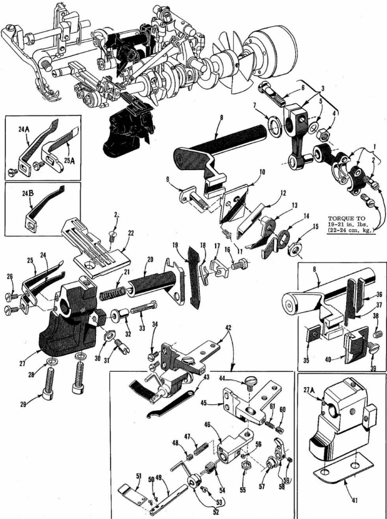
TORQUE TO 19-21 in. lbs. (22-24 cm. kg.) 24A 25A 24B TORQUE TO 19-21 in. lbs. (22-24 cm. kg.) 27 28 29 30 31 32 33 34 35 36 37 38 39 40 41 42 43 44 45 46 47 48 49 50 51 52 53 54 55 56 57 58 59 60 61 62 63 64 65 66 67 68 69 70 71 72 73 74 75 76 77 78 79 80 81 82 83 84 85 86 87 88 89 90 91 92 93 94 95 96 97 98 99UPPER AND LOWER KNIFE MECHANISM AND PRESSURE PLATE ASSEMBLY
| Ref.No. | PartNo. | Description | Amt.Req. |
| 1 | 39573 J | Upper Knife Drive Connecting Rod | 1 |
| 2 | 22587 J | Screw, for upper knife drive connecting rod | 2 |
| 3 | 39573 E | Upper Knife Driving Lever | 1 |
| 4 | 55235 E | Nut, for upper knife driving lever | 1 |
| 5 | 6042 A | Washer, for upper knife driving lever | 1 |
| 6 | 55235 D | Locking Stud, for upper knife driving lever | 1 |
| 7 | 39573 A | Upper Knife Driving Arm Washer | 1 |
| 8 | 39573 H | Upper Knife Driving Arm | 1 |
| 9 | 39571 C | Upper Knife Clamp Stud, for Styles 39500 QT,TM,TT | 1 |
| - | 39571 D | Upper Knife Clamp Stud, for Styles 39500 QS, RD, RL, RT, TK | 1 |
| 10 | 39572 | Upper Knife Holder Block, for Styles 39500 QS, RD, RL, RT, TK | 1 |
| - | 39572 A | Upper Knife Holder Block, for Styles 39500 QT,TM,TT | 1 |
| 11 | 22738 | Screw, for upper knife clamp stud, for all Styles except 39500 TJ | 1 |
| 12 | 39570 J | Upper Knife, for all Styles except 39500 TJ | 1 |
| 13 | 39571 F | Upper Knife Clamp, for all Styles except 39500 TJ | 1 |
| 14 | 39571 B | Upper Knife Chain Guard, for all Styles except 39500 TJ | 1 |
| 15 | 14077 | Nut, for upper knife clamp stud, for all Styles except 39500 TJ | 1 |
| 16 | 22588 J | Screw, for lower knife clamp | 1 |
| 17 | 39550 Z | Lower Knife Clamp | 1 |
| 18 | 39550 M | Lower Knife Clamp Spring | 1 |
| 19 | 39549 J | Lower Knife | 1 |
| 20 | 39550 N | Lower Knife Holder, for all Styles except 39500 TJ | 1 |
| - | 39550 S | Lower Knife Holder, for Style 39500 TJ | 1 |
| 21 | 39550 E | Lower Knife Holder Spring | 1 |
| 22 | Throat Plate (See Pages 39, 41) | 1 | |
| 23 | 22524 | Screw, for throat plate | 1 |
| 24 | 39525 | Needle Guard, front, for Styles 39500 QS, QT, RT, TJ, TM,TT | 1 |
| 24A | 39525 F | Needle Guard, front, for Style 39500 RL | 1 |
| 24B | 39525 M | Needle Guard, front, for Styles 39500 RD, TK | 1 |
| 25 | 39525 A | Needle Guard, rear, for Styles 39500 QS, QT, RT, TJ, TM, TT | 1 |
| 25A | 39525 N | Needle Guard, rear, for Styles 39500 RD, RL, TK | 1 |
| 26 | 22585 A | Screw, for needle guards | 2 |
| 27 | 39580 A | Throat Plate and Lower Knife Support Bracket, for all Styles except 39500 TK | 1 |
| 27A | 39580 AE | Throat Plate and Lower Knife Support Bracket, for Style 39500 TK | 1 |
| 28 | 39580 F | Washer, for throat plate and lower knife support bracket | 2 |
| 29 | 22653 B-12 | Screw, for throat plate and lower knife support bracket | 2 |
| 30 | 14077 | Nut, for lower knife holder locking screw | 1 |
| 31 | 22892 B | Locking Screw, for lower knife holder | 1 |
| 32 | 39550 C | Lower Knife Holder Locating Stud | 1 |
| 33 | 22729 B | Screw, for lower knife holder locating stud | 1 |
| 34 | 22569 C | Screw, for pressure plate assembly on Styles 39500 QT, RD,RL, RT, TM,TT- | 2 |
| 35 | 39571 A | Upper Knife Clamp Nut, for Style 39500 TJ | 1 |
| 36 | 39571 E | Upper Knife Clamp, for Style 39500 TJ | 1 |
| 37 | 39270 E | Upper Knife, for Style 39500 TJ | 1 |
| 38 | 22650 CB-4 | Set Screw, for upper knife clamp on Style 39500 TJ | 1 |
| 39 | 22829 | Screw, for upper knife holder on Style 39500 TJ | 1 |
| 40 | 39572 B | Upper Knife Holder, for Style 39500 TJ | 1 |
| 41 | 39580 E | Shim, for throat plate and lower knife support bracket on Style 39500 TK | 1 |
| 42 | 29480 GX | Pressure Plate Assembly, for Styles 39500 QT, RD, RL, RT, TM, TT | 1 |
| 43 | 21388 Y | Spanner Wrench | 1 |
| 44 | 35751 D | Shoulder Screw, for mounting bracket | 1 |
| 45 | 39531 J | Mounting Bracket | 1 |
| 46 | 39531 K | Shaft Bracket | 1 |
| 47 | 22597 E | Set Screw, for shaft bracket | 1 |
| 48 | 95 | Lock Screw, for shaft bracket | 1 |
| 49 | 39531 P | Pressure Plate Shaft | 1 |
| 50 | 22738 | Screw, for pressure plate | 2 |
| 51 | 39531 S | Pressure Plate | 1 |
| 52 | 39531 N | Actuating Collar | 1 |
| 53 | 22894 Y | Set Screw, for actuating collar | 1 |
| 54 | 39531 R | Pressure Plate Tension Spring | 1 |
| 55 | 15037 A | Lock Nut, for shoulder screw | 1 |
| 56 | 22743 | Set Screw, for pressure plate shaft | 1 |
| 57 | 39531 M | Pressure Plate Shaft Collar | 1 |
| 58 | 39531 H | Operating Lever | 1 |
| 59 | 77 A | Set Screw, for operating lever | 1 |
| 60 | 22580 A | Screw, for tension spring | 1 |
| 61 | 39531 L | Tension Spring, for shoulder screw | 1 |

| Ref.No. | PartNo. | Description | Amt.Req. |
| 1 | 22566 B | Screw, for foot lifter lever | 1 |
| 2 | 39555 F | Foot Lifter Lever Connecting Link | 1 |
| 3 | 660-142 | Cotter Pin, for foot lifter lever connecting link | 2 |
| 4 | 39555 D | Foot Lifter Intermediate Lever | 1 |
| 5 | 39555 B | Foot Lifter Lever Spring | 1 |
| 6 | 39555 | Foot Lifter Lever | 1 |
| 7 | 39555 C | Foot Lifter Lever Arm | 1 |
| 8 | 12538 | Lock Nut, for foot lifter lever arm | 2 |
| 9 | 22597 E | Screw, for foot lifter lever arm | 2 |
| 10 | 627 | Screw, for foot lifter lever arm | 1 |
| 11 | 12865 | Thrust Collar, for foot lifter lever shaft | 1 |
| 12 | 88 | Screw, for thrust collar | 2 |
| 13 | 39555 A | Foot Lifter Lever Shaft | 1 |
| 14 | 258 A | Nut, for presser arm screw pin | 1 |
| 15 | 22791 H | Screw Pin, for presser arm | 1 |
| 16 | 39556 F | Presser Arm | 1 |
| 17 | 22704 | Screw, for chain cutting knife, for Styles 39500 RD, RL, TK | 1 |
| 18 | 39556 K | Chain Cutting Knife, marked "J", for Styles 39500 RD, RL, TK | 1 |
| 19 | 605 A | Screw, for presser foot hold down plate, for all Styles except 39500 QS, TJ | 2 |
| 20 | 39556 H | Presser Foot Hold Down Plate, for all Styles except 39500 QS, TJ | 1 |
| 21 | Presser Foot (See Pages 39, 41) | 1 | |
| 22 | 43139 A | Nut, for looper thread eyelet screw | 2 |
| 23 | 22569 B | Screw, for looper thread eyelet mounting bracket | 1 |
| 24 | 39568 D | Looper Thread Eyelet Mounting Bracket | 1 |
| 25 | 39568 L | Upper Looper Thread Eyelet | 1 |
| 26 | 39568 B | Lower Looper Thread Eyelet | 1 |
| 27 | 376 A | Screw, for looper thread eyelets | 2 |
| 28 | 39568 E | Auxiliary Looper Thread Eyelet | 1 |
| 29 | 39568 R | Frame Looper Thread Eyelet | 1 |
| 30 | 22569 D | Screw, for frame looper thread eyelet | 1 |
| 31 | 22569 D | Screw, for frame needle thread eyelet | 1 |
| 32 | 39563 H | Frame Needle Thread Eyelet | 1 |
| 33 | 39592 AH | Nut, for tension post on all Styles except 39500 RD, RL, TK | 3 |
| - | 39592 AH | Nut, for tension post on Styles 39500 RD, RL, TK | 4 |
| 34 | 8372 A | Washer, for tension post on all Styles except 39500 RD, RL, TK | 3 |
| - | 8372 A | Washer, for tension post on Styles 39500 RD, RL, TK | 4 |
| 35 | 22806 A | Screw, for tension post mounting bracket | 1 |
| 36 | 22847 B | Screw, for tension post mounting bracket | 1 |
| 37 | 39592 AM | Tension Post Bar, for all Styles except 39500 RD, RL, TK | 1 |
| - | 39592 AN | Tension Post Bar, for Styles 39500 RD, RL, TK | 1 |
| 38 | 39592 AG-3 | Tension Post Mounting Bracket, for all Styles except 39500 RD, RL, TK | 1 |
| - | 39592 AG-5 | Tension Post Mounting Bracket, for Styles 39500 RD, RL, TK | 1 |
| 39 | 39592 AF | Tension Disc Felt, for all Styles except 39500 RD, RL, TK | 3 |
| - | 39592 AF | Tension Disc Felt, for Styles 39500 RD, RL, TK | 4 |
| 40 | 39592 AL | Tension Post, for all Styles except 39500 RD, RL, TK | 3 |
| - | 39592 AL | Tension Post, for Styles 39500 RD, RL, TK | 4 |
| 41 | 39592 AD | Thread Tension Disc, for all Styles except 39500 RD, RL, TK | 6 |
| - | 39592 AD | Thread Tension Disc, for Styles 39500 RD, RL, TK | 8 |
| 42 | 39592 AJ | Spring Shield, for all Styles except 39500 RD, RL, TK | 3 |
| - | 39592 AJ | Spring Shield, for Styles 39500 RD, RL, TK | 4 |
| 43 | 39592 AR-4 | Looper Thread Tension Spring, for Styles 39500 RD, RL, RT | 2 |
| - | 39592 AR-5 | Looper Thread Tension Spring, for Styles 39500 QS, QT, TJ, TK, TM, TT | 2 |
| - | 39592 AR-5 | Needle Thread Tension Spring, for Style 39500 TM | 1 |
| - | 39592 AR-8 | Needle Thread Tension Spring, for Styles 39500 QS, QT, RT, TJ, TT | 1 |
| - | 39592 AR-8 | Needle Thread Tension Spring, for Styles 39500 RD, RL, TK | 2 |
| 44 | 39592 AK | Tension Spring Ferrule, for all Styles except 39500 RD, RL, TK | 3 |
| - | 39592 AK | Tension Spring Ferrule, for Styles 39500 RD, RL, TK | 4 |
| 45 | 39592 AA | Needle Tension Nut, green, also for right needle on Styles 39500 RD, RL, TK | 1 |
| - | 39592 AB | Upper Looper Tension Nut, blue | 1 |
| - | 39592 AC | Lower Looper Tension Nut, red | 1 |
| - | 39592 Z | Left Needle Tension Nut, yellow, for Styles 39500 RD, RL, TK | 1 |
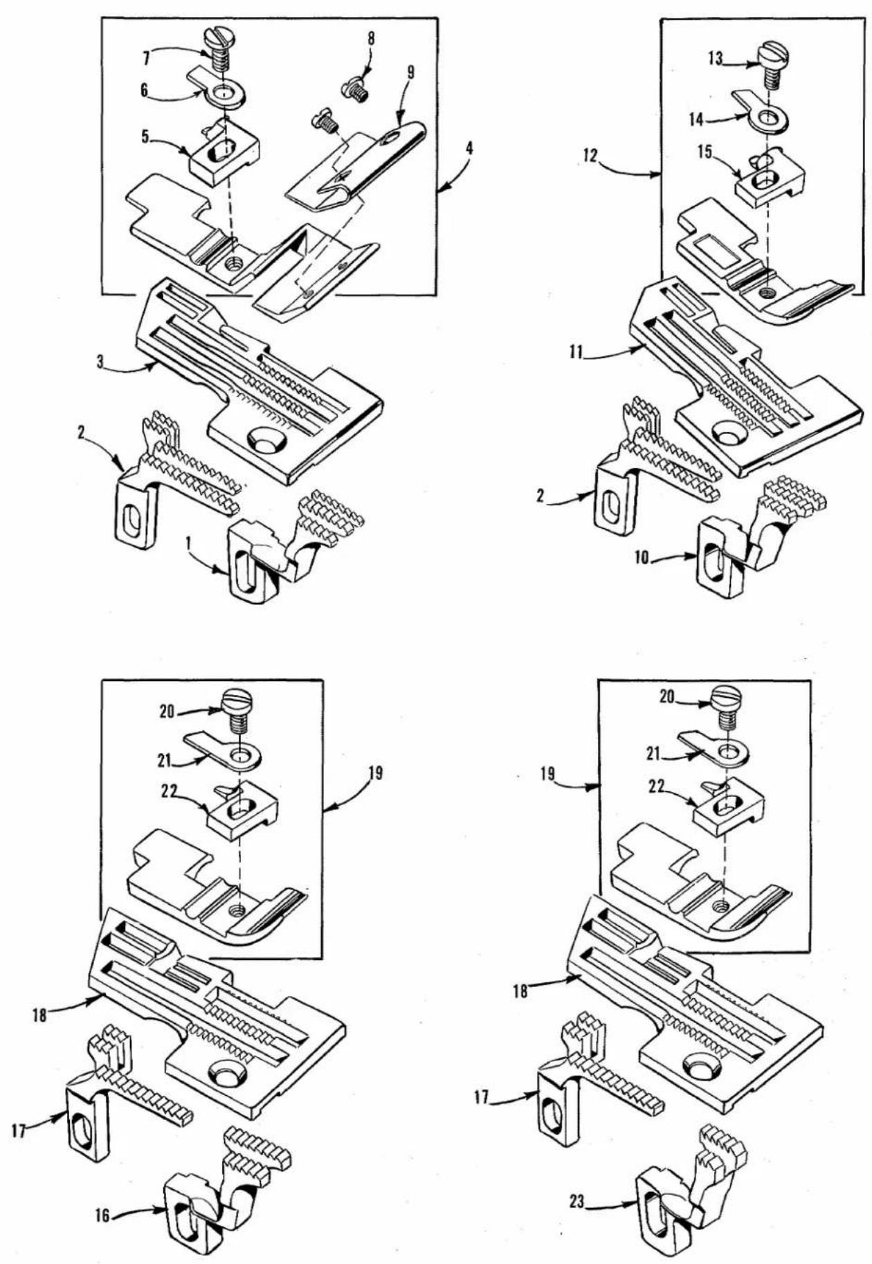
FEED DOGS, THROAT PLATES AND PRESSER FEET
| Ref. No. | Part No. | Description | Amt. Req. |
| 1 | 39526 S | Differential Feed Dog, marked "M", 16 t.p.i., for Styles 39500 QS, RT | 1 |
| 2 | 39505 S | Main Feed Dog, marked "R", 16 t.p.i., for Styles 39500 QS, QT, RT | 1 |
| 3 | 39524 S | Throat Plate, marked "AK", for Style 39500 QS | 1 |
| 4 | 39520 S | Presser Foot, for Style 39500 QS | 1 |
| 5 | 39597 S | Presser Foot Stitch Tongue, marked "EB" | 1 |
| 6 | 39530 G | Presser Foot Hinge Spring | 1 |
| 7 | 22768 B | Screw, for stitch tongue and hinge spring | 1 |
| 8 | 91 A | Screw, for stripper blade | 2 |
| 9 | 39530 F | Stripper Blade | 1 |
| 10 | 39526 T | Differential Feed Dog, marked "N", 16 t.p.i., for Style 39500 QT | 1 |
| 11 | 39524 T | Throat Plate, marked "AL", for Styles 39500 QT, TM, TT- | 1 |
| 12 | 39520 M | Presser Foot, for Styles 39500 QT, TM, TT | 1 |
| 13 | J87 J | Screw, for stitch tongue and hinge spring | 1 |
| 14 | 39530 G | Presser Foot Hinge Spring | 1 |
| 15 | 39597 T | Presser Foot Stitch Tongue, marked "EC" | 1 |
| 16 | 39526 AD | Differential Feed Dog, marked "AJ", 16 t.p.i., for Style 39500 RD | 1 |
| 17 | 39505 AD | Main Feed Dog, marked "AH", 16 t.p.i., for Styles 39500 RD, RL | 1 |
| 18 | 39524 W | Throat Plate, marked "AN", for Styles 39500 RD, RL, TK | 1 |
| 19 | 39520 AD | Presser Foot, for Styles 39500 RD, RL | 1 |
| 20 | 22768 B | Screw, for stitch tongue and hinge spring | 1 |
| 21 | 39530 | Presser Foot Hinge Spring | 1 |
| 22 | 39597 AD | Presser Foot Stitch Tongue, marked "EL" | 1 |
| 23 | 39526 AL | Differential Feed Dog, marked "AY", 16 t.p.i., for Style 39500 RL | 1 |
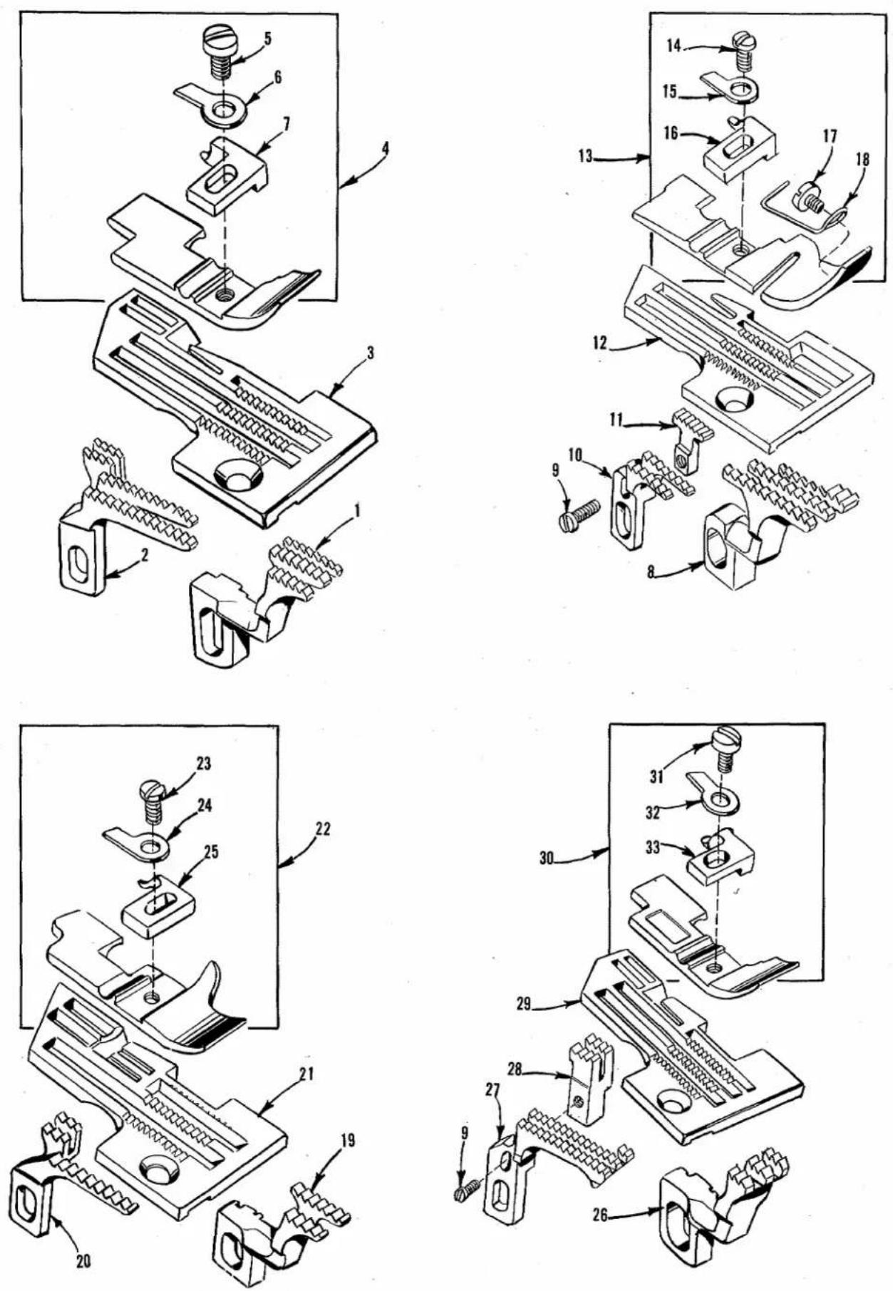
FEED DOGS, THROAT PLATES AND PRESSER FEET
| Ref.No. | PartNo. | Description | Amt.Req. |
| 1 | 39526 S | Differential Feed Dog, marked "M", 16 t.p.i., forStyles 39500 QS, RT---- | 1 |
| 2 | 39505 S | Main Feed Dog, marked "R", 16 t.p.i., for Styles39500 QS, QT, RT---- | 1 |
| 3 | 39524 AT | Throat Plate, marked "BF", for Style 39500 RT---- | 1 |
| 4 | 39520 AT | Presser Foot, for Style 39500 RT---- | 1 |
| 5 | J87 J | Screw, for stitch tongue and hinge spring---- | 1 |
| 6 | 39530 G | Presser Foot Hinge Spring---- | 1 |
| 7 | 39597 AT | Presser Foot Stitch Tongue, marked "ET"- | 1 |
| 8 | 39526 BF | Differential Feed Dog, marked "BZ", 12 t.p.i., forStyle 39500 TJ---- | 1 |
| 9 | 22747 | Screw, for chaining feed dog on Styles 39500 TJ, TM,TT---- | 1 |
| 10 | 39505 AS | Main Feed Dog, marked "FA", 12 t.p.i., for Style39500 TJ---- | 1 |
| 11 | 39505 AV | Chaining Feed Dog, marked "FB", 16 t.p.i., for Style39500 TJ---- | 1 |
| 12 | 39524 BF | Throat Plate, marked "BK", for Style 39500 TJ---- | 1 |
| 13 | 39520 BF | Presser Foot, for Style 39500 TJ---- | 1 |
| 14 | 22768 B | Screw, for stitch tongue and hinge spring---- | 1 |
| 15 | 39530 | Presser Foot Hinge Spring---- | 1 |
| 16 | 39597 P | Presser Foot Stitch Tongue, marked "EA"- | 1 |
| 17 | 22798 B | Screw, for presser foot tape guide---- | 1 |
| 18 | 39530 BF | Presser Foot Tape Guide---- | 1 |
| 19 | 39526 AT | Differential Feed Dog, marked "FF", 12 t.p.i., forStyle 39500 TK---- | 1 |
| 20 | 39505 AT | Main Feed Dog, marked "FE", 12 t.p.i., for Style39500 TK---- | 1 |
| 21 | 39524 W | Throat Plate, marked "AN", for Styles 39500 RD, RL,TK---- | 1 |
| 22 | 39529 W | Presser Foot, for Style 39500 TK---- | 1 |
| 23 | 22768 B | Screw, for stitch tongue and hinge spring---- | 1 |
| 24 | 39530 | Presser Foot Hinge Spring---- | 1 |
| 25 | 39597 W | Presser Foot Stitch Tongue, marked "EF"- | 1 |
| 26 | 39526 MM | Differential Feed Dog, marked "FM", 16 t.p.i., forStyle 39500 TM---- | 1 |
| - | 39526 BH | Differential Feed Dog, marked "PZ", 16 t.p.i., forStyle 39500 TT (has 5 teeth in each row)---- | 1 |
| 27 | 39505 MM | Main Feed Dog, marked "FL", 16 t.p.i., for Style39500 TM, TT---- | 1 |
| 28 | 39505 AW | Chaining Feed Dog, marked "FK", 16 t.p.i., for Style39500 TM, TT---- | 1 |
| 29 | 39524 T | Throat Plate, marked "AL", for Styles 39500 QT, TM,TT---- | 1 |
| 30 | 39520 M | Presser Foot, for Styles 39500 QT, TM, TT---- | 1 |
| 31 | J87 J | Screw, for stitch tongue and hinge spring---- | 1 |
| 32 | 39530 G | Presser Foot Hinge Spring---- | 1 |
| 33 | 39597 T | Presser Foot Stitch Tongue, marked "EC"- | 1 |
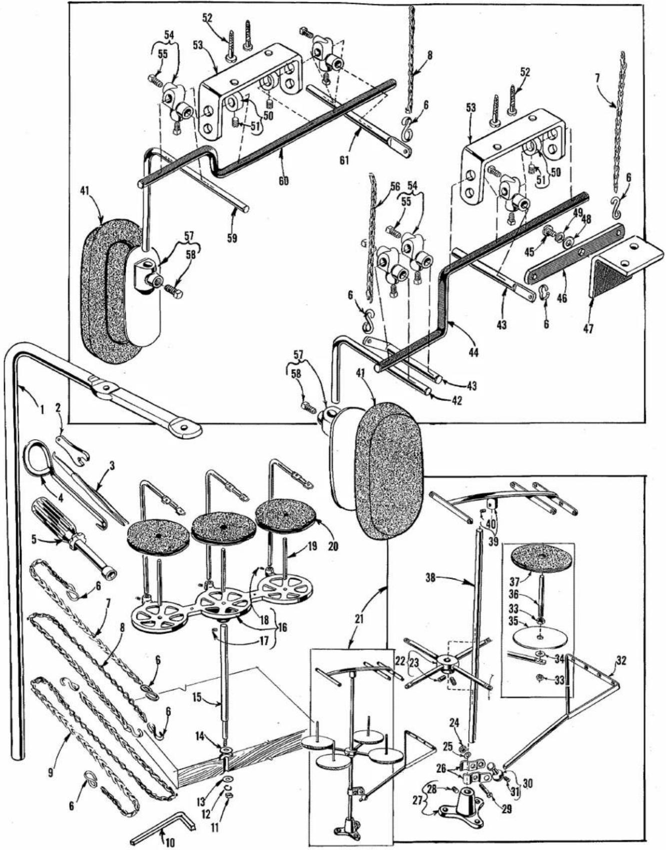
text_image
Technical diagram of a mechanical assembly with numbered components and labeled parts, likely for engineering or manufacturing documentation.THREAD STANDS, ACCESSORIES AND MISCELLANEOUS TOOLS
| Ref.No. | PartNo. | Description | Amt.Req. |
| 1 | 21113 F | Thread Stand Eyelet, for Styles 39500 QS, QT, RT, TJ, TM | 3 |
| 2 | 116 | Wrench, for 9/32 inch (7.14 mm) nut | 1 |
| 3 | 660-240 | Thread Tweezers | 1 |
| 4 | 21227 BF | Feed Eccentric Extractor Hook | 1 |
| 5 | 21388 AU | Socket Wrench, for 3/8 inch (9.52 mm) nuts holding feed eccentricis | 1 |
| 6 | 660-264 | "S" Hook, for chains | 2, 4 or 6 |
| * 7 | 421 D-4 | Presser Foot Lifter Chain | 1 |
| - | 421 D-18 | Pressure Plate Lifter Chain, for all Styles except 39500 TJ | 1 |
| 8 | 421 D-5 3/4 | Intermittent Differential Feed Control Chain, for all Styles except 39500 TJ | 1 |
| 9 | 421 D-34 | Presser Foot Lifter Treadle Chain | 1 |
| 10 | WR56 | Allen Wrench, 1/8 inch (3.17 mm) hexagon for Styles 39500 RD, RL, TK | 1 |
| 11 | 651 A-16 | Nut, for thread stand rod, for Styles 39500 QS, QT, RT, TJ, TM, TT | 1 |
| 12 | WA9 A | Lockwasher, for thread stand rod, for Styles 39500 QS, QT, RT, TJ, TM, TT | 1 |
| 13 | 652 J-16 | Washer, for thread stand rod, for Styles 39500 QS, QT, RT, TJ, TM, TT | 1 |
| 14 | 652 J-24 | Washer, for thread stand rod, for Styles 39500 QS, QT, RT, TJ, TM, TT | 1 |
| 15 | 21104 AA | Thread Stand Rod, for Styles 39500 QS, QT, RT, TJ, TM, TT | 1 |
| 16 | 21130 W-3 | Cone Support, for Styles 39500 QS, QT, RT, TJ, TM, TT | 1 |
| 17 | 22650 CE-6 | Screw, for cone support | 1 |
| 18 | 22650 CB-4 | Screw, for thread stand eyelet | 3 |
| 19 | 69 S | Spool Pin, for Styles 39500 QS, QT, RT, TJ, TM, TT | 3 |
| 20 | 21104 V | Pad, for thread cone, for Styles 39500 QS, QT, RT, TJ, TM, TT | 3 |
| 21 | 21101 H-4 | Thread Stand Complete, for Styles 39500 RD, RL, TK | 1 |
| 22 | 21114 D-4 | Spool Seat Support | 1 |
| 23 | 22651 CD-5 | Screw, for spool seat support | 2 |
| 24 | 21104 H | Nut, for lead eyelet ball split socket | 1 |
| 25 | 652-16 | Washer, for lead eyelet ball split socket | 1 |
| 26 | 21114 U | Lead Eyelet Ball Split Socket | 2 |
| 27 | 21114 A | Thread Stand Base | 1 |
| 28 | 22651 CD-4 | Screw, for thread stand base | 1 |
| 29 | 22810 | Screw, for lead eyelet ball split socket | 1 |
| 30 | 21114 T | Lead Eyelet Socket Ball | 1 |
| 31 | 22651 CD-4 | Screw, for lead eyelet socket ball | 1 |
| 32 | 21114 S-4 | Lead Eyelet | 1 |
| 33 | 258 A | Nut, for spool pin | 8 |
| 34 | 652-16 | Washer, for spool seat disc | 4 |
| 35 | 21114 | Spool Seat Disc | 4 |
| 36 | 21114 W | Spool Pin | 4 |
| 37 | 21104 V | Pad, for thread cone | 4 |
| 38 | 21104 B-20 | Thread Stand Rod | 1 |
| 39 | 21114 H-4 | Eyelet Support | 1 |
| 40 | 22651 CD-4 | Screw, for eyelet support | 1 |
| 41 | 660-168 | Knee Press Pad | 1 or 2 |
| *42 | 21663 A | Knee Press Plate Rod | 1 |
| *43 | 21663 J | Knee Press Rod, for presser foot on all Styles and for pressure plate on all Styles except 39500 QS, TJ, TK | 1 or 2 |
| *44 | 21663 H | Knee Press Shaft | 1 |
| *45 | 22557 A | Screw, for knee press lever | 1 |
| *46 | 21662 AH | Knee Press Lever | 1 |
| *47 | 21664 C | Bell Crank Bracket | 1 |
| *48 | 43137 E | Washer, for bell crank bracket | 1 |
| *49 | 39536 AD | Spring Washer, for bell crank bracket | 1 |
| 50 | 9271 | Collar | 2 or 3 |
| 51 | 98 | Screw, for collar | 1 |
| 52 | SC468 | Wood Screw | 2 or 6 |
| 53 | 21662 | Knee Press Bracket | 1 or 2 |
| 54 | 21665 | Knee Press Rod Connection | 2, 4 or 5 |
| 55 | 69 FD | Screw, for knee press rod connection | 2 |
| *56 | 421 D-8 | Pressure Plate Chain, for all Styles except 39500 QS, TJ, TK | 1 |
| 57 | 21664 | Knee Press Plate | 1 or 2 |
| 58 | 69 FD | Screw, for knee press plate | 1 |
| 59 | 21663 A | Knee Press Plate Rod | 1 |
| 60 | 21663 G | Knee Press Shaft, for differential feed adjustment | 1 |
| 61 | 21663 E | Lifter Length Rod | 1 |
| - | 28604 R | Container of Oil, 16 ounces, Spec. 174 (not shown) | 1 |
| - | 652-24 | Washer, for table top on Style 39500 TJ (not shown) | 8 |
| - | 660-458 | Dust Cover (not shown) | 1 |
* Available as extra send and charge items, for lifting presser foot and pressure plate using a knee press.
NOTE: Knee press parts for differential feed not furnished on Style 39500 TJ.
NUMERICAL INDEX OF PARTS
| Part No. | Page No. | Part No. | Page No. | Part No. | Page No. |
| WA9 A | 43 | 12934 A | 29 | 22729 D | 33 |
| 18 | 29 | 14077 | 31, 35 | 22729 E | 33 |
| 22 KH | 33 | 14077 A | 31 | 22738 | 35 |
| 25 CC | 29 | 15037 A | 35 | 22743 | 25, 35 |
| 28 | 29 | 21101 H-4 | 43 | 22747 | 41 |
| 30-106 Blk | 27 | 21104 B-20 | 43 | 22747 B | 27 |
| 40-46 | 27, 31 | 21104 H | 43 | 22764 | 31 |
| 50-774 Blk | 31 | 21104 V | 43 | 22768 | 31 |
| 51-103 Blk | 25 | 21104 AA | 43 | 22768 B | 39, 41 |
| 51-228 Blk | 27 | 21113 F | 43 | 22768 C | 27 |
| WR56 | 43 | 21114 | 43 | 22769 B | 27 |
| CO67 E | 27 | 21114 A | 43 | 22782 A | 31 |
| CO67 F | 29 | 21114 D-4 | 43 | 22791 H | 37 |
| 69 H | 25 | 21114 H-4 | 43 | 22798 B | 41 |
| 69 S | 43 | 21114 S-4 | 43 | 22806 A | 37 |
| 69 FD | 43 | 21114 T | 43 | 22810 | 43 |
| 77 | 33 | 21114 U | 43 | 22824 B | 29 |
| 77 A | 35 | 21114 W | 43 | 22829 | 35 |
| 77 Q | 27 | 21130 W-3 | 43 | 22847 B | 37 |
| 87 | 29 | 21227 BF | 43 | 22892 B | 35 |
| J87 J | 39, 41 | 21388 Y | 35 | 22894 C | 33 |
| 87 U | 27, 31, 33 | 21388 AU | 43 | 22894 D | 27 |
| 88 | 31, 37 | 21662 | 43 | 22894 Y | 35 |
| 88 A | 29 | 21662 AH | 43 | 22894 AE | 25, 33 |
| 88 B | 31 | 21663 A | 43 | 28604 R | 43 |
| 90 | 25 | 21663 E | 43 | 29126 DF | 33 |
| 91 A | 39 | 21663 G | 43 | 29477 GW | 25 |
| 93 | 31 | 21663 J | 43 | 29477 HJ | 25 |
| 94 | 31 | 21663 H | 43 | 29477 KE | 27 |
| 95 | 27, 35 | 21664 | 43 | 29477 MC | 27 |
| 97 | 33 | 21664 C | 43 | 29480 GX | 35 |
| 97 A | 27 | 21665 | 43 | 35751 D | 35 |
| 98 | 43 | 22503 F | 33 | 39151 | 33 |
| 116 | 43 | 22513 | 31 | 39198 D | 29 |
| 138 | 25 | 22524 | 35 | 39270 E | 35 |
| 154 GAS | 31 | 22541 | 25 | 39501 K | 25 |
| 154 GBS | 31 | 22541 A | 31 | 39501 DB | 25 |
| 161 | 31 | 22541 B | 25 | 39501 DC | 25 |
| 161 A | 31 | 22557 A | 43 | 39501 EB | 25 |
| 258 | 27, 31 | 22557 E | 29 | 39501 EC | 25 |
| 258 A | 37, 43 | 22562 A | 25, 33 | 39505 S | 39, 41 |
| 376 A | 37 | 22564 G | 33 | 39505 AD | 39 |
| 421 D-4 | 43 | 22565 | 25, 33 | 39505 AS | 41 |
| 421 D-5 3/4 | 43 | 22565 B | 29 | 39505 AT | 41 |
| 421 D-8 | 43 | 22565 F | 25, 27, 29 | 39505 AV | 41 |
| 421 D-18 | 43 | 22565 H | 33 | 39505 AW | 41 |
| 421 D-34 | 43 | 22565 S | 25, 33 | 39505 MM | 41 |
| SC468 | 43 | 22566 B | 37 | 39508 A | 33 |
| 482 C | 33 | 22569 | 25 | 39508 B | 33 |
| 605 A | 37 | 22569 B | 25, 27, 29, 37 | 39508 C | 33 |
| 627 | 37 | 39520 M | 39, 41 | ||
| 651 A-16 | 43 | 22569 C | 25, 31, 35 | 39520 S | 39 |
| 652-16 | 43 | 22569 D | 25, 37 | 39520 W | 41 |
| 652-24 | 43 | 22569 G | 31 | 39520 AD | 39 |
| 652 J-16 | 43 | 22569 K | 25 | 39520 AT | 41 |
| 652 J-24 | 43 | 22571 E | 25 | 39520 BF | 41 |
| 660-142 | 37 | 22580 A | 35 | 39521 D | 27 |
| 660-168 | 43 | 22585 A | 35 | 39521 G | 27 |
| 660-204 | 27 | 22586 R | 25 | 39524 S | 39 |
| 660-206 | 33 | 22587 J | 35 | 39524 T | 39, 41 |
| 660-207 | 31 | 22587 M | 27 | 39524 W | 39, 41 |
| 660-240 | 43 | 22588 J | 35 | 39524 AT | 41 |
| 660-243 | 25 | 22596 E | 31 | 39524 BF | 41 |
| 660-264 | 43 | 22596 H | 27 | 39525 | 35 |
| 660-268 | 27 | 22597 E | 35, 37 | 39525 A | 35 |
| 660-443 | 27 | 22650 CB-4 | 35, 43 | 39525 F | 35 |
| 660-458 | 43 | 22650 CE-6 | 43 | 39525 M | 35 |
| 666-94 | 27 | 22651 CD-4 | 43 | 39525 N | 35 |
| 666-255 | 33 | 22651 CD-5 | 43 | 39526 S | 39, 41 |
| 667-B-12 | 27 | 22653 B-12 | 27, 35 | 39526 T | 39 |
| 667 D-8 | 25 | 22653 D-4 | 25 | 39526 AD | 39 |
| 1025 L | 33 | 22657 D-12 | 25 | 39526 AL | 39 |
| 6042 A | 35 | 22704 | 37 | 39526 AT | 41 |
| 8372 A | 25, 29, 37 | 22726 L | 31 | 39526 BF | 41 |
| 9271 | 43 | 22728 A | 29 | 39526 BH | 41 |
| 12538 | 37 | 22729 B | 35 | 39526 MM | 41 |
| 12865 | 37 | 39530 | 39, 41 |
NUMERICAL INDEX OF PARTS
| Part No. | Page No. | Part No. | Page No. | Part No. | Page No. |
| 39530 F | 39 | 39550 C | 35 | 39582 W | 25 |
| 39530 G | 39, 41 | 39550 E | 35 | 39582 AD | 25 |
| 39530 BF | 41 | 39550 M | 35 | 39582 AE | 25 |
| 39531 H | 35 | 39550 N | 35 | 39582 AF | 25 |
| 39531 J | 35 | 39550 S | 35 | 39582 AG | 25 |
| 39531 K | 35 | 39550 Z | 35 | 39582 AK | 25 |
| 39531 L | 35 | 39551 G | 31 | 39582 BG | 25 |
| 39531 M | 35 | 39551 H | 31 | 39582 BH | 25 |
| 39531 N | 35 | 39551 J | 31 | 39582 BK | 25 |
| 39531 P | 35 | 39552 C | 31 | 39582 BL | 25 |
| 39531 R | 35 | 39552 J | 31 | 39582 BM | 25 |
| 39531 S | 35 | 39552 P | 27 | 39582 BV | 25 |
| 39532 A | 25 | 39552 R | 31 | 39590 | 27 |
| 39534 A | 31 | 39552 T | 31 | 39590 D | 27 |
| 39534 B | 29 | 39552 U | 27 | 39590 G | 27 |
| 39534 H | 31 | 39552 Z | 31 | 39590 H | 27 |
| 39535 D | 29 | 39555 | 37 | 39590 J | 27 |
| 39535 E | 29 | 39555 A | 37 | 39590 N | 27 |
| 39535 H | 25 | 39555 B | 37 | 39590 P | 27 |
| 39535 J | 29 | 39555 C | 37 | 39590 R | 27 |
| 39536 E | 29 | 39555 D | 37 | 39590 S | 27 |
| 39536 F | 31 | 39555 E | 27 | 39590 T | 27 |
| 39536 G | 31 | 39555 F | 37 | 39590 X Y | 27 |
| 39536 H | 31 | 39555 N | 27 | 39591 A | 27 |
| 39536 J | 29 | 39556 A | 25 | 39591 B | 27 |
| 39536 K | 29 | 39556 F | 37 | 39591 H | 27 |
| 39536 L | 29 | 39556 H | 37 | 39591 K | 27 |
| 39536 M | 29 | 39556 K | 37 | 39591 L | 27 |
| 39536 N-247 | 29 | 39557 | 25 | 39592 Z | 37 |
| 39536 N-248 | 29 | 39557 A | 25 | 39592 AA | 37 |
| 39536 N-249 | 29 | 39557 B | 25 | 39592 AB | 37 |
| 39536 P | 29 | 39557 C | 25 | 39592 AC | 37 |
| 39536 R | 29 | 39557 E | 25 | 39592 AD | 37 |
| 39536 S | 29 | 39557 F | 25 | 39592 AF | 37 |
| 39536 U | 29 | 39563 F | 25 | 39592 AG-3 | 37 |
| 39536 V | 29 | 39563 G | 31 | 39592 AG-5 | 37 |
| 39536 W | 29 | 39563 H | 37 | 39592 AH | 37 |
| 39536 X | 29 | 39563 W | 25 | 39592 AJ | 37 |
| 39536 Y | 29 | 39568 A | 31 | 39592 AK | 37 |
| 39536 AB | 29 | 39568 B | 37 | 39592 AL | 37 |
| 39536 AC | 29 | 39568 D | 37 | 39592 AM | 37 |
| 39536 AD | 31, 43 | 39568 E | 37 | 39592 AN | 37 |
| 39536 AF | 31 | 39568 G | 25 | 39592 AR-4 | 37 |
| 39536 AH | 29 | 39568 J | 25 | 39592 AR-5 | 37 |
| 39536 AJ | 29 | 39568 L | 37 | 39592 AR-8 | 37 |
| 39538 | 31 | 39568 P | 25 | 39593 C | 25 |
| 39540 B-4 | 31 | 39568 R | 37 | 39593 D | 25 |
| 39540 B-6 | 31 | 39568 Y | 31 | 39593 H | 25 |
| 39540 B-10 | 29 | 39570 J | 35 | 39594 G | 25 |
| 39540 B-12 | 29 | 39571 A | 35 | 39594 H | 25 |
| 39540 B-14 | 29 | 39571 B | 35 | 39594 N | 27, 31, 33 |
| 39540 B-16 | 29 | 39571 C | 35 | 39594 R | 25 |
| 39540 C | 31 | 39571 D | 35 | 39595 | 25 |
| 39541 A | 27 | 39571 E | 35 | 39597 P | 41 |
| 39543 | 33 | 39571 F | 35 | 39597 S | 39 |
| 39543 A | 33 | 39572 | 35 | 39597 T | 39, 41 |
| 39543 E | 33 | 39572 A | 35 | 39597 W | 41 |
| 39543 K | 33 | 39572 B | 35 | 39597 AD | 39 |
| 39543 M | 33 | 39573 A | 35 | 39597 AT | 41 |
| 39543 P | 33 | 39573 E | 35 | 39599 | 25 |
| 39543 S | 33 | 39573 H | 35 | 39635 A | 31 |
| 39543 T | 33 | 39573 J | 35 | 39636 | 29 |
| 39543 U | 33 | 39573 K | 27 | 39636 A | 29 |
| 39543 W | 33 | 39573 AA | 27 | 39636 B | 29 |
| 39543 X | 33 | 39578 K | 25 | 39636 C | 29 |
| 39543 Y | 31 | 39578 M | 29 | 39636 D | 29 |
| 39544 | 33 | 39578 P | 29 | 39636 E | 29 |
| 39544 B | 33 | 39578 T | 25 | 43137 E | 43 |
| 39544 D | 33 | 39578 W | 25 | 43139 A | 29, 37 |
| 39544 J | 33 | 39580 A | 35 | 43243 N | 27 |
| 39544 L | 27 | 39580 E | 35 | 51295 B | 25 |
| 39544 N | 33 | 39580 F | 35 | 53634 C | 29, 31 |
| 39544 S | 33 | 39580 J | 31 | 55235 D | 35 |
| 39544 U | 33 | 39580 AE | 35 | 55235 E | 35 |
| 39544 V | 33 | 39582 F | 25 | 61351 K-625 | 31 |
| 39549 J | 35 | 39582 V | 25 |
Union Special Wants to Help You Cut Sewing Machine Maintenance Costs
Union Specialis offering two practical systems to help pinpoint and reduce your sewing machine maintenance costs: a record keeping system to help spot machines requiring abnormally high maintenance, and a parts inventory system to speed routine repairs.
Machine Maintenance Records
Repair-prone machines or inexperienced competent operators can eat up your maintenance dollars in short order. To help spot these problems, Union Special suggests two variations of a simple maintenance record keeping system using cards provided by Union Special.com
The first system utilizes a "Machine Maintenance Record" card (Form 237) for each sewing machine in a plant. When a repair is required, the card is pulled from the file and the repair date, parts used, and their cost are entered in the spaces provided and the card is refiled.

text_image
MACHINE MAINTENANCE RECORD MARKER NAME STYLE TYPE NEEDLE SERIAL NO. GATE PUNCH. DATE SWIKOL.PART USED COST CASE SWIKOL.PART USED COST / / / / / / / / / / / / / / / / Machine Maintenance Record card NAME STICKLY LISTING BY FORM 001-124 (SHEET 11.2.5)The second system is normally used when more detailed information on repair costs is desired. Two record cards are used: a "Repair Request Card" (Form 234), and a "Machine Repair Record" (Form 233). When a machine requires service, the forelady or foreman fills out the top of a "Repair Request Card" and gives it to a mechanic. He fills in the time the repair work is started, the parts used and their cost,
and the completion time. This data is then transferred to the permanent "Machine Repair Record" kept in the office.
Whichever system is used, management now has an invaluable tool to reduce needless maintenance costs.
Repair Part Inventories
While record keeping tells management which machines require abnormally high maintenance, it does little to help reduce the downtime caused by routine repairs. To alleviate this situation, Union Special recommends that manufacturers establish a formal parts inventory system for each type of sewing machine they operate.
Excessive machine downtime and wasted hours by mechanics can be eliminated with an orderly in-plant inventory of the most commonly needed parts. There is no longer a need to cannibalize other machines for spare parts. Long waits for deliveries are avoided and machine downtime is kept to a minimum. The cost of a parts inventory is small when the overall savings are considered.

text_image
MACHINE REPAIR RECORD CARD DATE: SYMBOL REPAIR REQUEST CARD Date: MACKER ORDER. MACKER NAME... ORDER: MACKER NO. ORATORIE NO. PARTS USED PAGE: RIGHT NUMBER: COPY: FORM 233- Machine Repair Record card FORM 234- Repair Request Card TIME STARTED TIME COMPLETED MECHANICS NO. : KSS### ### ### ### ### ###
For free sample copies of the machine record cards and spare part inventory lists for a variety of the most popular machines, contact your local Union Special Representative or write direct to Union Special.
Union Special Industrial Sewing Equipment
Style 39500 QS
Suggested Minimum Spare Parts List*
| Part Number | Description | Minimum Quantity Per 5 Machines | Part Number | Description | Minimum Quantity Per 5 Machines |
| 39520 S | Presser foot | 1 | 39570 J | Upper knife | 4 |
| 39530 | Presser foot hinge spring | 2 | 39549 J | Lower knife | 4 |
| 39597 S | Stitch tongue marked “EB” | 1 | 22588 A | Screw for lower knife clamp | 1 |
| 39530 F | Stripper blade | 1 | 39508 B | Lower looper | 1 |
| 91 A | Screw for stripper blade | 2 | 39508 A | Upper looper, marked “CC” | 1 |
| 39505 S | Main feed dog, 16 TPI, marked “R” | 1 | 22564 G | Screw for upper looper | 2 |
| 94 | Screw for main feed dog | 2 | 39551 F | Needle clamp stud | 1 |
| 39526 S | Differential feed dog, 16 TPI, marked “M” | 1 | 14077 | Nut for upper knife and needle clamp stud | 2 |
| 93 | Screw for differential feed dog | 2 | 22596 E | Screw for needle driving arm | 2 |
| 39524 S | Throat plate, marked “AK” | 1 | 21225-1/8 | Looper gauge | 1 |
| 22524 | Throat plate screw | 2 | 29484 | Screw assortment | 1 |
| 154 GAS | Needles (specify size) | 200 |
| 2017 | 2016 | |
| Cost of sales | 3,458 | 3,394 |
| Gross profit | 1,000 | 1,000 |
| Net profit | 1,000 | 1,000 |

natural_image
World map with latitude and longitude grid lines, showing continents and oceans (no text labels)WORLDWIDE SALES AND SERVICE
Union Special Corporation maintains sales and service facilities throughout the world. These offices will aid you in the selection of the right sewing equipment for your particular operation. Union Special Corporation representatives and service technicians are factory trained and are able to serve your needs promptly and efficiently. Whatever your location, there is a qualified representative to serve you.
Corporate Office:
One Union Special Plaza
Huntley, IL 60142
Phone: 708·669·5101
Fax: 708·669·1096
European Distribution Center:
Union Special GmbH
Raiffeisenstrasse 3
D-71696 Möglingen, Germany
Tel: 49·07141·247·0
Fax: 49·7141·247·100
Brussels, Belgium
Charlotte, N.C.
Commerce, CA
El Paso, TX
Hong Kong, China
Huntley, IL
Leicester, England
Lille, France
Miami, FL
Milan, Italy
Mission, TX
Möglingen, Germany
Montreal, Quebec
Osaka, Japan
Other Representatives throughout
all parts of the world.

Finest Quality
Union Special® INDUSTRIAL SEWING EQUIPMENT