39600FS - Nähmaschine Union Special - Kostenlose Bedienungsanleitung
Finden Sie kostenlos die Bedienungsanleitung des Geräts 39600FS Union Special als PDF.

Benutzerfragen zu 39600FS Union Special
0 Frage zu diesem Gerät. Beantworten Sie die, die Sie kennen, oder stellen Sie Ihre eigene.
Eine neue Frage zu diesem Gerät stellen
Laden Sie die Anleitung für Ihr Nähmaschine kostenlos im PDF-Format! Finden Sie Ihr Handbuch 39600FS - Union Special und nehmen Sie Ihr elektronisches Gerät wieder in die Hand. Auf dieser Seite sind alle Dokumente veröffentlicht, die für die Verwendung Ihres Geräts notwendig sind. 39600FS von der Marke Union Special.
BEDIENUNGSANLEITUNG 39600FS Union Special
SECOND EDITION

Union Special® INDUSTRIAL SEWING EQUIPMENT
CATALOG NO. 127FA
STYLES
39600FA
39600FB
39600FP
39600FQ
39600FR
39600FS
HI-STYLED HIGH SPEED
FOUR AND FIVE THREAD
SAFETY STITCH MACHINES
WITH
LONG 401 STITCH LOOPER TRAVEL
Catalog No. 127 FA
INSTRUCTIONS
FOR
ADJUSTING AND OPERATING
LIST OF PARTS
CLASS 39600
Four and Five Thread Safety-Stitch Machines with
Long 401 Stitch Looper Travel
STYLES
39600 FA
39600 FB
39600 FP
39600 FQ
39600 FR
39600 FS
Second Edition
Copyright © 1973
by
Union Special Corporation
Rights Reserved in All Countries
UNION SPECIAL CORPORATION
INDUSTRIAL SEWING MACHINES
CHICAGO
Printed in U.S.A.
April, 1979
IDENTIFICATION OF MACHINES
Each UNION SPECIAL machine is identified by a Style number which is stamped into the name plate on the machine. Style numbers are classified as Standard and Special. Standard Style numbers have one or more letters suffixed but never contain the letter "Z". Example: "Style 39600 FA". Special Style numbers contain the letter "Z". When only minor changes are made in a standard machine, a "Z" is suffixed to the Standard Style number. Example: "Style 39600 FAZ".
Styles of machines similar in construction are grouped under a class number which differs from the style number in that it contains no letters. Example: "Class 39600".
The distance between the rows of stitches or between the needles is represented by a gauge number measured in 1/64ths of an inch, going from left to right. The width of overedge is represented by a fraction. Collectively, the gauge number and the width of overedge represent the machine gauge. Example: "5-1/8". Thus, 5-1/8 gauge represents a distance for 5/64 inch between the left needle (401 stitch) and the right needle (503 or 504 stitch) and the 1/8 represents the width of overedge to the right of the right hand needle.
APPLICATION OF CATALOG
This catalog applies specifically to the Standard Styles of machines as listed herein. It can also be applied with discretion to some Special Styles of machines in this class. Reference to direction, such as right, left, front, back, etc., are given from the operator's position while seated at the machine. Operating direction of handwheel is away from operator.
STYLES OF MACHINES
Two Curved Needles, Left Needle in Front, Differential Feed, Light to Medium and Heavy Duty Machines, Trimming Mechanism with Spring Pressed Lower Knife, Automatic Lubricating System. Increased 401 Looper Travel.
39600 FA Two loopers, one spreader, four thread dual stitch; 401 double locked stitch on left needle and 503 two thread overedge stitch on right rear needle. Straight upper knife parts. Light to medium duty machine for simultaneously seaming and overedging on sport and dress shirts, ladies' blouses, street and house dresses, coat and jacket linings, pillow cases and similar operations on light to medium weight durable press or conventional materials. Seam specification, (401-503) 515-SSa-2; standard gauge and seam widths are 3-1/8, 5-1/8 and 12-3/16; stitch range, 8 to 16 per inch; cam adjusted main and differential feeds. Maximum recommended speed 6500 R.P.M.
39600 FB Same as Style 39600 FA except three loopers, five thread dual stitch; 401 double locked stitch on left needle and 504 three thread overedge stitch on right rear needle. Seam specification (401-504) 516-SSa-2. Standard gauge and seam widths are 5-1/8 and 12-3/16.
39600 FP Same as Style 39600 FA, except medium to heavy duty and equipped with wide straight upper knife parts, for operations on slacks, jackets, sport shirts, street and house dresses, coat linings, shoulder pads and similar operations on medium to medium heavy weight materials. Maximum recommended speed 6000 R.P.M.
39600 FQ Same as Style 39600 FP, except three loopers, five thread dual stitch; 401 double locked stitch on left needle and 504 three thread overedge stitch on right rear needle. Seam specification (401-504) 516-SSa-2.
STYLES OF MACHINES (Continued)
39600 FR Same as Style 39600 FA, except medium to heavy duty and angular upper knife parts, for operations on slacks, jackets, sport shirts, jacket and coat linings, shoulder pads and similar operations on medium to medium heavyweight materials. Maximum recommended speed 6000 R.P.M.
39600 FS Same as Style 39600 FR, except three loopers, five thread dual stitch; 401 double locked stitch on left needle and 504 three thread overedge stitch on right rear needle. Seam specification (401-504) 516-SSa-2.
SPEED RECOMMENDATION
Class 39600 machines have been tested in their complete stitch range at their maximum rated speeds. Varied field conditions, severity and cleanliness of the sewing operation may necessitate operating at a lower speed. When operating from 50-100% machine running cycle and a longer than recommended stitch length, it may be necessary to reduce the machine's speed by 10-15%.
These machines are precision manufactured and tested sewing machines. To obtain maximum performance, the machine should be operated at 1000 R. P. M. below maximum recommended speed for the first 20 days of field operation. This will minimize readjustment of precision mechanisms.
OILING
CAUTION! Oil was drained from machine when shipped, so reservoir must be filled before beginning to operate. Oil capacity of Class 39600 is seven ounces. A straight mineral oil of a Saybolt viscosity of 90 to 125 seconds at 100^ Fahrenheit should be used.
Machine is filled with oil at spring cap in top cover. Oil level is checked at sight gauge on front of machine. Red bulb on oil level indicator should show between gauge lines when machine is stationary.
Machine is automatically lubricated. No oiling is necessary, other than keeping main reservoir filled. Check oil daily before the morning start; add oil as required.
To maintain maximum recommended speed and serviceability of this equipment when operating continuously, the oil must be changed at least every six months. In no case should oil remain in machine for more than one year.
The oil drain plug screw is located at the back of machine near bottom edge of base. It is a magnetic screw designed to accumulate possible foreign materials which may have entered the crank case. It should be removed and cleaned periodically.
NEEDLES
Each UNION SPECIAL needle has both a type and size number. The type number denotes kind of shank, point, length, groove, finish and other details. The size number, stamped on the needle shank, denotes largest diameter of blade, measured in thousandths of an inch, midway between shank and eye. Collectively, type and size number represent the complete symbol which is given on the label of all needles packaged and sold by Union Special.
Two needles having different lengths are used in these machines. The shorter needle for the overedge stitch, located at the right, is Type 154 GAS. It is a round shank, round point, curved blade, standard length, single groove, struck groove, spotted, chromium plated needle and is available in sizes 055/022, 065/025, 070/027, 075/029, 080/032, 090/036, 100/040, 110/044, 125/049, 140/054, 150/060.
The longer needle for the 401 stitch, located at the left, is Type 161 GS. It is a round shank, round point, curved blade, Class C, double groove, struck groove, spotted, chromium plated needle and is available in sizes 070/027, 075/029, 080/032, 090/036, 100/040, 110/044, 125/049.
To have needle orders promptly and accurately filled, an empty package, a sample needle, or the type and size number should be forwarded. Use description on label. A complete order would read: "1000 Needles, Type 154 GAS, Size 080/032".
Selection of proper needle size is determined by size of thread used. Thread should pass freely through needle eye in order to produce a good stitch formation.
Success in the operation of UNION SPECIAL machines can be secured only by use of needles packaged under our brand name, UnionSpecial®, which is backed by a reputation for producing highest quality needles in materials and workmanship and for more than three-quarter of century.
CHANGING NEEDLES
Release pressure on presser foot by turning the presser foot release, bushing (A, Fig. 1 or 1A) and swinging presser arm (B) out of position. Turn handwheel in operating direction (away from operator) until needle holding screws (A, Fig. 2) are just exposed from behind presser spring plunger (B) and accessible to screwdriver. Loosen screw and withdraw needle. When replacing needles observe the position of the flat which is at the left of the shank and be sure the needle is inserted the full depth to the combination eyelet and stop plate (C).
THREADING
Only parts involved in threading are shown in threading diagrams (Fig. 1 and 1A). Parts are placed in their relative positions for clarity.
Thread from thread stand (C) is threaded through the upper holes of tension thread guide (D) from front to back and then through the lower holes from back to front. It should be noted on Styles 39600 FB, FQ and FS that thread No. 5 (overedge needle - green color code) is threaded through the tension thread guide (D), first through the upper hole back to front, second through the middle hole front to back and third through the lower hole back to front. All threads then continue between the tension discs (K), through tension post slot (L) in tension post (H) and on through its proper hole in front thread guide (N).
It will simplify the threading of these machines to follow the recommended sequence as designated by the numbers assigned to each thread, starting with thread No. 1, then No. 2, etc. The various eyelets and guides on the machine for each thread have been color coded to further aid the threading process.
Thus the threading sequence for Styles 39600 FA, FP and FR (503 stitch) is as follows: Thread No. 1, 401 looper thread - blue color code; thread No. 2, 503 upper looper thread - yellow color code; thread No. 3, 401 needle thread - red color code; thread No. 4, overedge needle thread - green color code.
The threading sequence for Styles 39600 FB, FQ and FS (504 stitch) is as follows: Thread No. 1, 504 lower looper thread - black color code; thread No. 2, 401 looper thread - blue color code; thread No. 3, 504 upper looper thread - yellow color code; thread No. 4, 401 needle thread - red color code; thread No. 5, overedge needle thread - green color code.
Before beginning to thread, swing cloth plate open, turn handwheel in operating direction until the needles (P) are at their highest position, release pressure on presser foot by turning presser foot release bushing (A), and swing presser arm (B) out of position.
RAISE 401 LOOPER THREAD TAKE-UP EYELET (W) BY RELEASING EYELET LATCH (X) AND RAISING EYELET.
THREADING 401 LOOPER (Blue Color Code)
Double end of 401 looper thread (No. 1 on Styles 39600 FA, FP and FR; No. 2 on Styles 39600 FB, FQ and FS) and lead it through the rear eyes of looper thread take-up eyelet (W) from right to left and forward through its front eyelet. Return eyelet to its lower position by pressing it down. When eyelet is in correct position, latch (X) will snap into place. Thread down through the vertically positioned 401 looper thread eyelet (Y). Bring needle arm to bottom of its stroke. Insert doubled

text_image
E Tension Nut F Tension Spring Ferrule G Tension Spring H Tension Post J Spring Shield K Tension Discs L Tension Post Slot M Tension Disc Felt 3 4 2 1 TO RAISE EYELET "W" FOR THREADING PRESS "X" TO RELEASE C A D 1 2 3 4 X EYELET MUST BE IN LOCKED POSITION AE B N AD W R S AF P AA 65° 45° 35° 30° 4 3 Y Z Fig. 1THREADING 401 LOOPER (Blue Color Code, Continued)
end of thread into right eye of 401 looper (Z) from back to front, push through approximately an inch or so of thread. Holding tweezers in left hand insert doubled end of thread into left eye, using about 3/16 inch projection of thread from point of tweezers. DO NOT THREAD LOOPER WITH NEEDLE LOOP AROUND LOOPER. REMOVE LOOP, OTHERWISE MACHINE WILL NOT SEW.
THREADING UPPER LOOPER (Yellow Color Code)
Turn handwheel until point of upper looper (AC) is all the way left. Double end of upper looper thread (No. 2 on Styles 39600 FA, FP and FR; No. 3 on Styles 39600 FB, FQ and FS) and lead the thread through the auxiliary looper thread eyelet (AA) from back to front and then through both eyes of the upper looper thread eyelet (R) from left to right across the inside of needle thread cam pull-off (S).
After pulling up the upper looper thread tube assembly (AB), lead thread down through tube assembly and pull thread out bottom of tube. Push tube down and insert the thread through the eye of the upper looper (AC) from front to back.
THREADING 401 NEEDLE THREAD (Red Color Code)
Turn handwheel in operating direction to lower needle driving arm to the bottom of its stroke. Double end of 401 needle thread (No. 3 on Styles 39600 FA, FP and FR; No. 4 on Styles 39600 FB, FQ and FS) and lead thread through both eyes of the 401 needle thread eyelet (AD) from left to right, passing over the outside of the needle thread cam pull-off (S). Then thread through eyelet (AE) from back to front. On Styles 39600 FA, FP and FR, now thread through the left eye of the needle driving arm eyelet (AF) and finally through the eye of the left needle (P).
On Styles 39600 FB, FQ and FS, after passing the thread through eyelet AE from back to front, then thread through the upper eye of the needle driving arm eyelet (AF), through the lower eye and then through the eye of the left needle (P). NOTE: To thread the needle, raise the needle by rotating the handwheel in the operating direction and thread the needle front to back.
THREADING OVEREDGE NEEDLE (Green Color Code)
Turn handwheel in operating direction until the needle is at its highest position.
Pass the overedge needle thread (No. 4 on Styles 39600 FA, FP and FR) through the right eye of the needle driving arm eyelet (AF) and finally through the eye of the right needle (P) from front to back.
On Styles 39600 FB, FQ and FS, pass the overedge needle thread (No. 5) through both eyes of the upper needle thread eyelet (AD) from right to left, passing over the outside of the needle thread cam pull-off (S), then thread through eyelet (AG) from right to left and then down through hole in top cover needle thread eyelet (AH). Thread right needle (P) from front to back.
THREADING 504 LOWER LOOPER (Black Color Code)
Double end of lower looper thread (No. 1 on Styles 39600 FB, FQ and FS) and lead it through both eyes of the lower looper thread eyelet (R) from right to left across the inside of needle thread cam pull-off (S). Lead thread back under hook of fabric guard bracket (T) and through eye of frame looper thread guide (U). Turn handwheel in operating direction until heel of lower looper (V) is all the way to the left, then thread through left eye, entering from the rear and then through the right eye entering from the front. Left eye of lower looper can be threaded easily if tweezers are held with the left hand.

text_image
E Tension Nut F Tension Spring Ferrule G Tension Spring H Tension Post J Spring Shield K Tension Discs L Tension Post Slot M Tension Disc Felt D TO RAISE EYELET "W" FOR THREADING PRESS "X" TO RELEASE C A TO RAISE EYELET "W" FOR THREADING PRESS "X" TO RELEASE EYELET MUST BE IN LOCKEL POSITION AE N AD X W AF AA R S P Y AC AB 3 1 2 3 4 5 6 7 8 9 10 11 12 13 14 15 16 17 18 19 20 21 22 23 24 25 26 27 28 29 30 31 32 33 34 35 36 37 38 39 40 41 42 43 44 45 46 47 48 49 50 51 52 53 54 55 56 57 58 59 60 61 62 63 64 65 66 67 68 69 70 71 72 73 74 75 76 77 78 79 80 Fig. 1ATHREAD TENSION
The amount of tension on the needle and looper threads is regulated by the knurled tension nuts (E, Fig. 1). Tension on the threads should be only enough to secure proper stitch formation. Using a postal scale, the measurements are taken with the needles at the top of their stroke and pulled in the direction as indicated. As a start the tensions for the 515 stitch type may be as follows:
401 needle thread; 2 to 2 1/2 oz. straight out of lower eye of needle driving arm eyelet (AF) with needle driving arm in its most rearward position.
Overedge needle thread; 1 1/2 to 2 oz. straight out of front thread guide (N).
401 looper thread; 2 oz. straight out of looper thread eyelet (Y).
Upper looper thread; 2 1/2 oz. straight out of upper looper thread eyelet (R) when needle driving arm is in its most rearward position.
Further refinement in tension adjustment is discussed at the conclusion of the adjusting instructions.
text_image
G F E D H C B AFig. 2
PRESSER FOOT PRESSURE
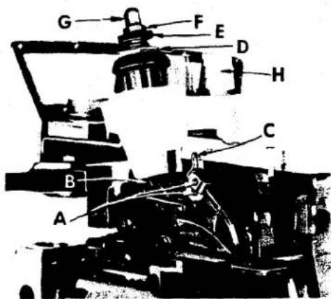
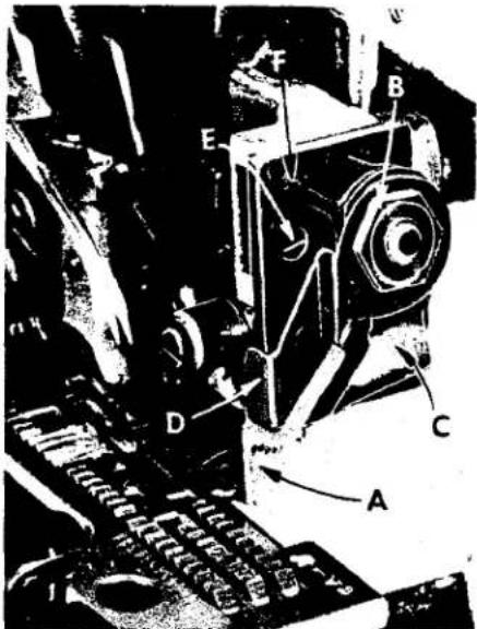
Sufficient pressure to feed work uniformly should be maintained. Should it be necessary to increase or decrease amount of pressure on presser foot loosen lock nut (D, Fig. 2) and turn the adjusting screw (E). Adjusting screw has a right hand thread so tightening increases the pressure, loosening decreases pressure. When pressure adjusting screw (E) has been properly set, tighten lock nut (D). With presser foot resting on the throat plate, position locking nut (F) so that its under surface is approximately 1/32 inch to 1/16 inch from the top surface of adjusting screw (E). Set the cap (G) against the locking nut (F).
FEED ECCENTRICS
Feed eccentrics used in these machines have been selected to produce approximately 11
stitches per inch on Styles 39600 FA and FB and 10 stitches per inch on Styles 39600 FP, FQ, FR and FS. It will be noted that part numbers 39540 B-10 and 39540 B-11 for Styles 39600 FA and FB, and 39540 B-9 and 39540 B-10 for Styles 39600 FP, FQ, FR and FS are the main feed and differential feed eccentricities respectively. Minor numbers of the part symbol indicate approximately the number of stitches obtainable when using that eccentric. Unless otherwise specified, machine will be shipped with above eccentricities.
Generally speaking, differential (right hand) feed eccentric determines the number of stitches produced; the main (left hand) feed eccentric is selected in relation to the degree and direction of stretch of material being sewn, or the type of operation.
The following stitch number feed eccentrics are available under No. 39540 B; 4, 5, 6, 7, 8, 9, 10, 11, 12, 13, 14, 15, 16, 18, 20, 22, 24, 26, 28, 30, 32, 34, 36, 40. Only two eccentrics are supplied with each machine. Additional eccentrics may be ordered separately. To order an eccentric, use No. 39540 B with a minor number suffixed to indicate number of stitches desired. Example: "39540 B-10".
It is suggested that the following sequence be followed: Before assembling the sewing parts, remove cloth plate, fabric guard, chip guard, upper knife assembly and lower knife holder assembly.
SETTING THE NEEDLES
Release the pressure on presser arm and swing arm out of position. Insert both needles (Type 161 GS for the 401 stitch and Type 154 GAS for the overedge stitch) into the left and right holes, respectively, of the needle driving arm (A, Fig. 3), so that the butt ends contact the needle driving arm thread eyelet (C, Fig. 2). Secure needles in this position with clamp screws (A, Fig. 2).
With the throat plate assembled in position, the needles should center in the throat plate needle holes. To align the needles, loosen clamp screw (B, Fig. 3) and reposition the needle driving arm to the right or left as required. The height of the needle driving arm is correct when the point of the left needle is 5/8 inch above the throat plate (Fig. 3) when at the top of its stroke. Tighten clamp screw (B) after correct height has been obtained and needles have been centered in the throat plate needle holes. Remove throat plate

text_image
A B 5" 8Fig. 3
SETTING 503 STITCH LOWER SPREADER

text_image
A 1/8 C BFig. 4
Insert the lower spreader (A, Fig. 4) into bar (B). With lower spreader at left end of its stroke, set spreader point 1/8 inch from centerline of right needle (Fig. 4) using gauge No. 21225-1/8. Do not have lower spreader deflecting needle. Do not lock nut (C) because the spreader point will have to be set to the needle scarf after the rear needle guard has been assembled and positioned. (See paragraph under "Final Setting of Lower Spreader").
SETTING 503 STITCH REAR NEEDLE GUARD
Set the rear needle guard (A, Fig. 5) as high as possible without interfering with either the lower spreader or movement of the lower knife holder, but still inposition to deflect the needle forward .002 to .004 inch. Screw (B) is used to set rear needle guard. Make sure there is no interference between rear needle guard and lower spreader.
FINAL SETTING OF 503 STITCH LOWER SPREADER
Now complete the lower spreader adjustment. As lower spreader moves to the right its point should be set into the needle scarf (C, Fig. 5) until the needle springs forward from the rear needle guard surface. another .002 to .004 inch. This setting
FINAL SETTING OF 503 STITCH LOWER SPREADER (Continued)
text_image
Technical diagram of a mechanical device with labeled parts A, B, C, D, and EFig. 5
is obtained by rocking the spreader forward or backward around its shank. Recheck the 1/8 inch spreader gauge setting and tighten nut (C, Fig. 4).
SETTING 503 STITCH FRONT NEEDLE GUARD
Assemble front needle guard (D, Fig. 5). When lower spreader is springing needle off rear guard, set the front needle guard as close as possible to the needle without touching. Screw (E) is used to adjust and set the front needle guard. After making this setting, assure there is no interference between needle guards and differential feed dog.
SETTING 503 STITCH UPPER LOOPER
Insert upper looper (A, Fig. 6) in its holder. Screw (B) holds the looper in its holder and permits looper to be pushed in or out, or turned around its shank. Screw (C) on the collar, holds looper holder in the shaft and allows the holder to be rotated or adjusted laterally.
text_image
C B 5 6 VERTICAL AFig. 6
Preliminary Setting: When looper is at the right end of its stroke, looper holder should be set to position the looper shank about vertical (Fig. 6). The top end of the looper shank should extend approximately 5/64 inch above holder (Fig. 6).
Set looper to pass just behind hump of lower spreader, with approximately .002 inch clearance between looper and lower spreader (Fig. 7).
Next, turn handwheel until loop-er is at left end of its travel: check the setting so point of looper extends about 5/32 inch to the left of needle (Fig. 8).

text_image
.002 CLEARANCEFig. 7
Now check setting between looper and needle. If needle rubs the back of looper, pull looper out of its holder slightly and rotate the looper holder forward a short distance. These same adjustments, in opposite movement, will reduce the clearance between looper and needle. Reset to lower spreader (Fig. 7).
SETTING 401 STITCH REAR NEEDLE GUARD
Insert rear needle guard into the hole in the throat plate support bracket. Set height of guard (F, Fig. 5) approximately 3/16 inch below the throat plate seat. Bring the 401 needle down until its point is 1/64 inch below the widest portion of the guarding surface. Then bring the guard forward to deflect the needle forward
SETTING 401 STITCH REAR NEEDLE GUARD (Continued)
from .003 to .005 inch. Then lock the guard in place with set screw (G).
SETTING 401 STITCH LOOPER
Insert 401 stitch looper into looper holder and press down until the butt end of the shank strikes the looper shaft. Looper will be at correct height. Tighten the looper clamp screw while working the looper blade to and fro to secure accurate seating of clamp screw against flat on shank.

text_image
5" 32Fig. 8

text_image
1" 16Fig. 9
With looper at the right end of its stroke, set looper 1/16 inch from centerline of left needle (Fig. 9) using looper gauge No. 21225-1/16. Loosen looper holder binder screw with a 7/64 inch hexagonal allen key to position the looper.
Viewing machine from the left end, set the looper point to lie in the scarf of the needle within .002 inch clearance (Fig. 10). Retighten looper holder binder screw.
While hand turning machine through cycle observe the action of the needle with relation to the looper. As needle rises from the bottom of its stroke the looper will approach the needle from right side and pass behind at top of needle scarf without striking. Further rising of the needle will result in the looper point entering the scarf. Furthermore, since the needle point is coming off the rear guard, the needle will resume its normal position by moving to the rear, resulting in a close relation of the needle and looper, or actual contact, until scarf passes looper. On the down stroke, the needle should pass behind the looper without the point glancing off the guarding surface of the looper.

text_image
.002 CLEARANCEFig. 10
Set front needle guard as close as possible to the needle when looper point is behind the needle and flush with the left side of needle. Also, front needle guard should be set so there is from 1/64 to 1/32 clear- ance between it and bottom of looper blade. Turn handwheel in operating direction, making complete revolutions to check whether needle is disturbed or pinched.
For convenience the looper may now be threaded as shown in (Fig. 1 or 1A) and as described under paragraph "To Thread 401 Looper". Replace differential feed dog, throat plate, lower knife holder and reset upper knife. Check cutting action with thread.
SETTING THE FEED DOGS
Assemble main and differential feed dogs (A, B, Fig. 11).
Feed dogs should be level with the throat plate surface by rotating feed tilting adjusting pin (C). This pin raises or lowers the back end of feed bar. Feed dogs should be level at the time teeth first appear above the throat plate. Screw (D) locks the feed tilting adjusting pin in place. Now set feed dogs at highest point of travel. Main and differential feed dog teeth should be set 3/64 inch above the throat plate.

text_image
Technical diagram of a mechanical assembly with labeled parts A through HFig. 11
SETTING THE LOWER KNIFE
Replace the lower knife holder assembly. In replacing the lower knife holder assembly, tighten screw (E, Fig. 11) so that when the face of the flange on sleeve (F) seats against throat plate mounting bracket (G), a free lateral motion of the lower knife and holder assembly is obtained when the knife is manually pressed at its upper corner. Lower knife (H) should be set with cutting edge flush with throat plate surface. Adjustments are made with hexagonal head screw (J) which holds the lower knife. Lower knife is spring pressed against the upper-knife, so no lateral adjustment is necessary when the width of trim is changed.
Lower knife may be secured in any position by tightening screw (K) against the knife holder shaft. Set the desired width of trim by measuring from the right edge of lower knife to needle. Lock lower knife holder shaft with screw (K).
SETTING THE UPPER KNIFE (Styles 39600 FA, FB, FP and FQ)
Replace upper knife assembly. Clamp upper knife (A, Fig. 12) in position, setting allen screw (B) to hold clamp (C) against the upper knife. At bottom of its stroke, front cutting edge of upper knife should extend not less than 1/64 inch below cutting edge of the lower knife.
After upper knife has been set for proper width of trim, screw (D) should be tightened to lock upper knife holding block (E) in place.
text_image
Technical diagram of an electrical device with labeled components A, B, C, D, and EFig. 12
SETTING THE UPPER KNIFE (Styles 39600 FR and FS)
Replace the upper knife assembly. Clamp upper knife (A, Fig. 13) in position, setting nut (B) to hold clamp (C) in its most clockwise position against upper knife. At the bottom of its stroke, front cutting edge of upper knife should extend not less than 1/64 inch below cutting edge of lower knife. The chain guard (D) should be set down against the upper knife and back from the cutting edge.
SETTING THE UPPER KNIFE (Continued) (Styles 39600 FR and FS)
After upper knife has been set for proper width of trim, screw (E) should be tightened to lock upper knife holding block (F) in place. This will simplify resetting when upper knife is replaced.
SETTING THE STITCH LENGTH
Length of stitch is determined by the combination of feed eccentricis used. Outer (left) eccentric (A, Fig. 14) actuates main (rear) feed dog; while the inner (right) eccentric (B) actuates the differential (front) feed dog.
In assembling feed eccentrics, be sure hubs are facing each other. Be careful not to damage shaft or key. Tighten nut (C) securely.
To change feed eccentric, remove nut (C) and washer (D) from end of shaft (E). Turn handwheel in operating direction until key slot in eccentric is toward front. Using hooked eccentric extractor (F), supplied with machine, reach behind eccentric as shown and withdraw eccentric. It may be necessary to move handwheel back and forth slightly during extraction.
text_image
Technical diagram of a mechanical assembly with labeled parts A through FFig. 13
If eccentrics are unusually tight fitting, in addition to removing nut (C) and washer (D, Fig. 15) from shaft (E), it may be helpful to remove nut (G) and feed driving connection (H). Then continue as originally suggested.
SETTING THE PRESSER FOOT

text_image
A B C D E FFig. 14
Assemble the presser foot to presser arm. With needle in high position, swing presser arm into sewing position and set the presser foot to align needle holes (front and back) and flat on throat plate. The front edge of needle hole in presser foot must be aligned with front edge of needle hole in throat plate. It is also important that the bottom of the presser foot be flat on the throat plate. If necessary, presser foot can be realigned with throat plate slots by shifting the foot lifter lever shaft (H, Fig. 16). To move the shaft, loosen collar screws (B, Fig. 16) and clamp screw (G) and then shift the foot lifter lever shaft to the left or right as required. Retighten collar screws and clamp screw.
The foot lifter lever arm (A, Fig. 16) and the collar (B) secure the shaft. Be sure the presser arm does not bind and rise when presser foot release bushing is unlocked.
Adjust lifter lever stop screw (C) so that presser foot can be raised no higher than upper looper will permit: then lock the nut (D). There should be from 1/16 to 1/8 inch free motion of foot lifter lever before the presser foot begins to rise. This
SETTING THE PRESSER FOOT (Continued)
adjustment should be made with screw (E) and locked with nut (F). Re-assemble the chip guard. fabric guard and cloth plate. To assemble chip guard, turn handwheel until upper knife assembly reaches its highest position.
503 STITCH NEEDLE THREAD CONTROL
text_image
Technical diagram of a mechanical assembly with labeled components A through H, showing internal components and directional arrows.Fig. 15
While sewing on material, check needle thread control as follows: Usually all needle thread is drawn on needle down stroke. At the top of needle stroke, thread should be just tight enough to feed chain off stitch tongue. The stitch tends to pull down slightly if excessive thread is pulled on the up stroke.
503 STITCH UPPER LOOPER THREAD CONTROL
With material under presser foot, set upper looper thread eyelet (R, Fig. 1 or 1A) back and down far enough so the thread is taut when the looper reaches its extreme left position. Looper
thread eyelet should be about horizontal.
THREAD TENSIONS
Before proceeding, balance both tensions to give a normal appearing stitch. Moderate change in these tensions will not markedly affect the purl.
SPECIAL ADJUSTMENTS
· SKIPPING: For occasional skipping, check and/or adjust as outlined below:
-
Recheck lower spreader - needle setting. See "Setting the Needles".
-
Recheck spreader - upper looper crossing. See "Setting 503 Stitch Upper Looper".
-
Check clearance between needle and upper looper. See that upper looper moves far enough left past the needle.
Settings 1 and 2 should be made quite carefully. If it can be determined by appearance that skip is definitely not a needle loop skip, reposition looper thread eyelet (R, Fig. 1 or 1A) by lowering it slightly and bringing eyelet holes in close to bend in looper thread pull-off (S). After this change, increase the looper thread tension as much as possible without distorting the stitch.

text_image
E F A G B C H S DFig. 16
STARTING TO OPERATE
Be sure the machine is threaded according to threading diagram (Fig. 1 or 1A).
With thread tensions light, set looper thread eyelet about horizontal and in the center of its front to back location.
STARTING TO OPERATE (Continued)
Operate machine slowly, with presser foot in place. Make sure that chain forms and moves off the tongue freely.
SETTING 401 NEEDLE THREAD EYELETS
Bring needle thread through its respective eyelets as shown in Fig. 1 or 1A and as described in paragraph "Threading 401 Needle Thread". Do Not thread the needle. Lower needle to the bottom of its stroke. Position needle thread pull-off eyelet (AD, Fig. 1 or 1A) so that the thread is spaced 1/16 inch from the needle thread pull-off cam (Fig. 17). With the needle at the top of its stroke, the needle thread pull-off eyelet should be positioned so that there is 1/64 inch clearance between the thread and the needle thread pull-off cam (Fig. 17). The frame thread eyelet should be centered in its slot and set vertically.
NOTE: This setting will require changing, depending upon the type of 401 stitch that is desired.

text_image
1/16 1/64Fig. 17
SETTING 401 LOOPER THREAD EYELETS
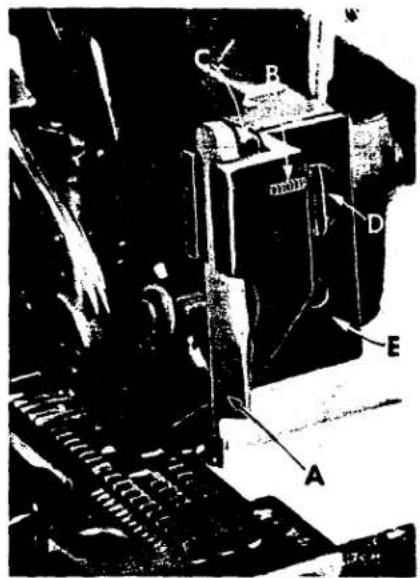
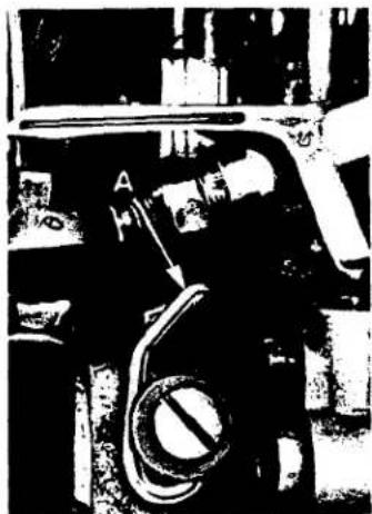
Set 401 looper thread take-up cam eyelet so rear eyelet hole is directly under looper thread cast-off corner of cam (A, Fig. 18) when cam is at its most rearward position. Front and rear eyelet holes to be set horizontally. Looper thread eyelet (A, Fig. 19) to be set vertically and approximately centered in its slot.
Pull several feet of thread through the looper to provide slack while checking the tension. Turn handwheel in operating direction until the needle is totally raised. Pulling the thread straight towards the operator, through the looper thread eyelet (A, Fig. 19), adjust tension with the knurled nut (H, Fig. 2) to approximately 2 ounces.
TIMING 401 STITCH LOOPER THREAD CAST-OFF
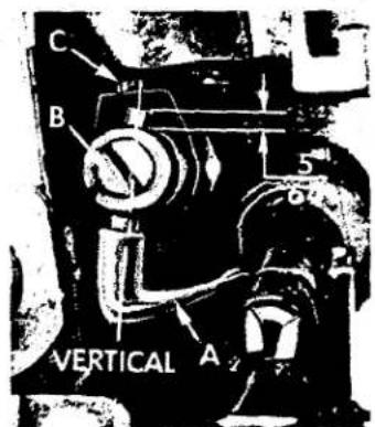
When the 401 looper thread cam is correctly positioned on the needle arm shaft, the cast-off corner (A, Fig. 18) will be 3/4 inch vertically below the top surface of the bed, when the needle arm is at its highest position (Fig. 18). This adjustment is

text_image
B 3 O VERTICALFig. 18
made at the factory, but if checked and moved, it must be observed that the cam functions as a thrust collar for the needle arm shaft and correct thrust must be maintained. If this setting is correct, the casting-off may be timed. To change the time of casting-off, move the cast-off blade (B) up or down, rotating it about its holding screw. Set cast-off blade to cast-off looper thread when the needle point is between the bottom and top of the looper.
SEWING OFF 401 STITCH
Drawing of the needle thread is controlled by the needle thread eyelet. Moving the eyelet towards the operator will tend to have the thread drawn from the cone on the upstroke of the needle arm travel and will tighten the needle thread in the seam that is being sewn.
Moving the eyelet towards the rear, tends to draw the thread on the downstroke and will loosen the needle thread in the seam.
Observe the action of the looper thread take-up at the bottom of the needle stroke. The looper thread is lying across the cam lobes, slack from the previous casting-off. As the needle arm rises to the top, the looper thread will begin to tighten across the cam until cast-off will again occur and the looper thread will lie in the crotch of the cast-off blade (B, Fig. 18).
Only enough tension should be carried on the looper thread to resist friction of looper and eyelet system. Thread should be pulled off only during the return travel of the looper from left to right and cease at casting-off.
natural_image
Close-up of a mechanical component with a circular valve and handle (no visible text or symbols)Fig. 19
ASSEMBLING AND ADJUSTING SEWING PARTS FOR 504 STITCH
The setting and adjustment of the needles, upper looper, front and rear needle guards as described earlier for the 503 stitch are applicable when making similar adjustments for the 504 stitch. Also, the adjusting and setting of the lower looper used in the 504 stitch formation is similar to the setting of the lower spreader used in the 503 stitch formation.
TO REMOVE CRANKSHAFT
text_image
Technical diagram of a mechanical assembly with labeled components and directional arrows indicating motion or flow.Fig. 20
Crankshaft can be withdrawn more easily if these steps are followed:
-
Drain oil by removing plug screw located at back of machine near bottom edge of base.
-
Remove top and bottom covers of machine.
-
Remove the feed eccentric nut and washer (F, Fig. 20) and, with the aid of the eccentric extractor, slip off the eccentrics (G).
-
Remove key (H).
-
Remove two counterweights (J). Identify these counterweights so that they will be reassembled in the proper place.
-
Remove screw (K) which holds crankshaft split bearing. This screw is reached through bottom of bed casting.
-
Remove caps of bearings on crankshaft at points A, B, D and E. When re-assembling bearing caps make sure they are in their original position. Trademarks are stamped on both halves of the caps and both trademarks should be on the same side of the bearings. Also, screws should be reassembled in the same holes from which they were removed.
TO REMOVE CRANKSHAFT (Continued)
text_image
A B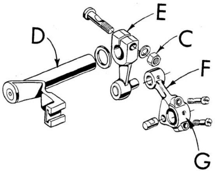
text_image
D E C F GFig. 21
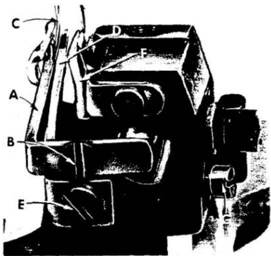
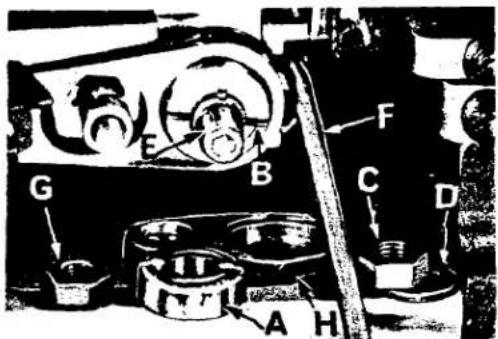
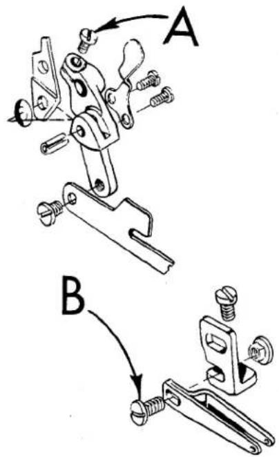
- Loosen clamp screw (A, Fig. 21) which holds eyelet bracket and swing bracket up. Loosen screw (B); swing eyelet up. Loosen clamp nut (C) which holds the upper knife driving arm (D). Access to clamp nut is through top cover. Draw driving arm to the left until upper knife driving lever (E) and connecting rod (F) drop, allowing removal of bearing cap (G). This is at bearing point (C, Fig. 20) on crankshaft. Observe same precautions when reassembling cap as described in paragraph 7.
- Remove screw (L, Fig. 20) which holds inner right crankshaft bearing. This screw is reached through bottom of bed casting.
- Loosen two screws (M) in fan collar; remove both halves of cooling fan.
- Remove screw (N); take off pulley cap (P).
- Loosen two screws (R); remove pulley (S).
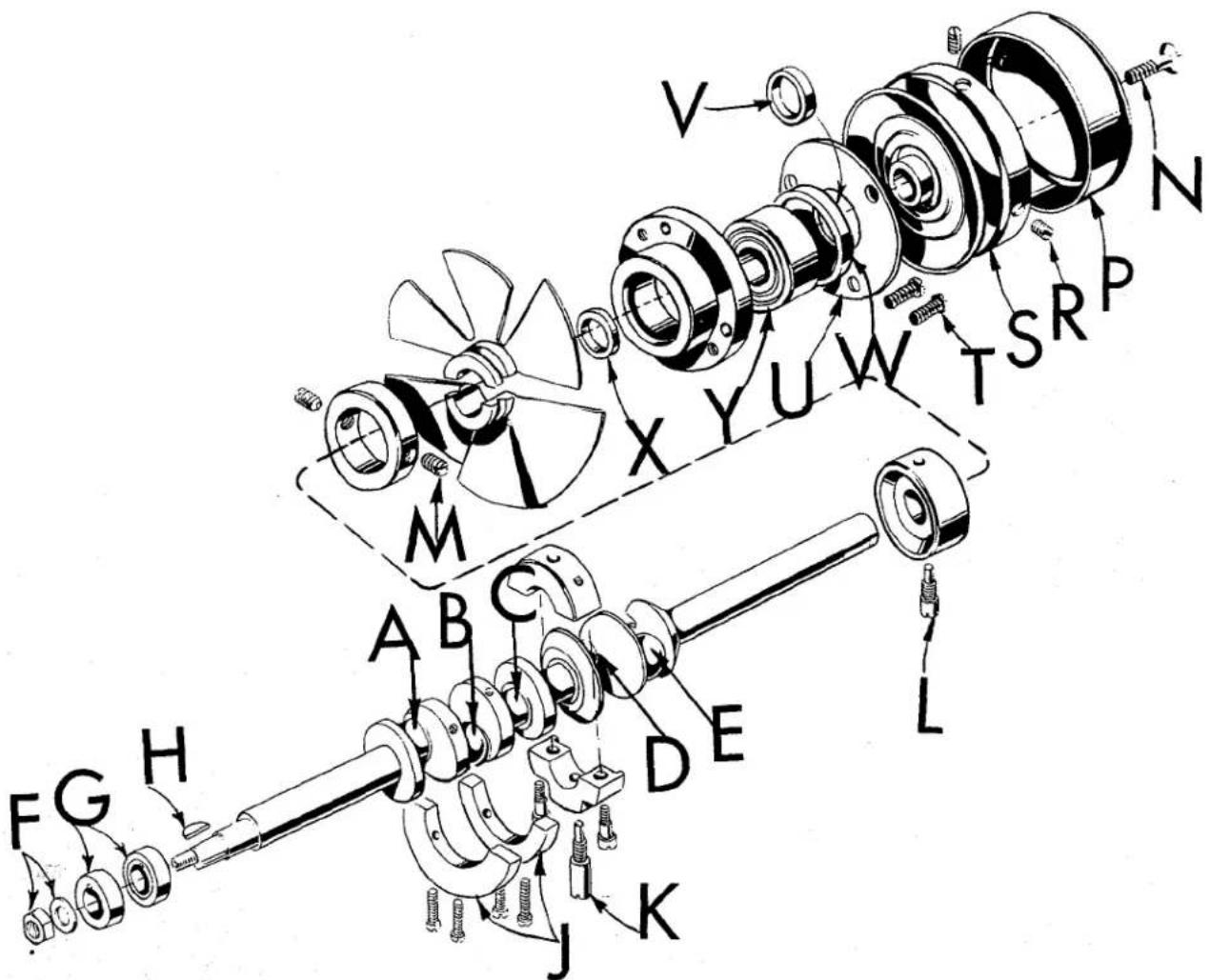
- Remove three screws (T); take off bearing retaining plate (U); also, spacer collars (V) and (W) may be removed at this time.
- Crankshaft may now be removed.
- If necessary to replace ball bearing (Y), it can be pressed off shaft on an arbor press. In replacing the bearing it must be pressed on carefully until it seats against ground thrust washer (X).
- Carefully observing reverse of the foregoing operations should simplify reassembly of crankshaft. Checking exploded view drawings for location of various parts and constant testing for binds during reassembly will also prove helpful.
- Before reassembling, thoroughly clean and dry the top and bottom covers and gaskets. Before reassembling bottom cover make sure that spring pressed oil wick which lubricates left crankshaft bearing is inserted in hole in casting and that it contacts shaft. The wick stands vertically on its spring against bottom cover. Coat the oil drain plug with a sealing compound before reassembling to prevent oil leakage. No. 1 Crane Lead Seal is recommended.
ORDERING REPAIR PARTS
ILLUSTRA TIONS
This catalog has been arranged to simplify ordering repair parts. Exploded views of various sections of the mechanism are shown so that the parts may be seen in their actual position in the machine. On the page opposite the illustration will be found a listing of the parts with their part numbers, description and the number of pieces required in the particular view being shown.
Numbers in the first column are reference numbers only, and merely indicate the position of that part in the illustration. Reference numbers should never be used in ordering parts. Always use the part number listed in the second column.
Component parts of sub-assemblies which can be furnished for repairs are indicated by indenting their descriptions under the description of the main sub-assembly. Example:
| 29 | 29477 KN | Crankshaft and Needle Driving Crank Assembly, forStyles 39600 FA and FB, all gauges----1 |
| 29477 KP | Crankshaft and Needle Driving Crank Assembly, forStyles 39600 FP, FQ, FR and FS, all gauges----1 | |
| 30 | 29477 MC | Needle Driving Arm Crank and Connecting RodAssembly----1 |
| 31 | 22587 M | Screw, for needle driving arm connectingrod----2 |
| 32 | 22596 H | Screw, for needle driving arm crank----1 |
| 33 | 22768 C | Screw, for connecting rod pin----1 |
| 34 | 51-228 Blk. | Vent Plug----1 |
| 35 | 39541 A | Feed Drive Eccentric Key----1 |
| 36 | 30-106 Blk. | Wood Plug, for crankshaft----1 |
| 37 | CO67 E | Cork Plug----1 |
| 38 | 40-46 | Washer----1 |
| 39 | 258 | Nut----1 |
It will be noted in the above example that the connecting rod and needle bearing are not listed. The reason is that replacement of these parts individually is not recommended, so the complete sub-assembly should be ordered.
Where parts for Styles 39600 FA, FB, FP, FQ, FR and FS are not the same, the difference will be shown in the illustrations or mentioned in the descriptions. When a part is used in all the machines covered by this catalog no machine style will be mentioned.
At the back of the book will be found a numerical index of all the parts shown in this book. This will facilitate locating the illustration and description when only the part number is known.
IDENTIFYING PARTS
When the construction permits, each part is stamped with its part number. Parts too small for a complete catalog stamping are identified by letter symbols which distinguish one part from another that is similar in appearance.
Part numbers represent the same part, regardless of catalog in which they appear.
IMPORTANT! ON ALL ORDERS, PLEASE INCLUDE PART NAME AND STYLE OF MACHINE FOR WHICH PART IS ORDERED.
USE GENUINE NEEDLES AND REPAIR PARTS
Success in the operation of these machines can be secured only with genuine UNION SPECIAL Needles and Repair Parts as furnished by the Union Special Corporation, its subsidiaries and authorized distributors. They are designed according to the most scientific principles, and are made with utmost precision. Maximum efficiency and durability are assured.
Genuine needles are packaged with labels marked Union Special®. Genuine repair parts are stamped with the Union Special trademark, U S Emblem. Each trademark is your guarantee of the highest quality in materials and workmanship.
TERMS
Prices are strictly net cash and subject to change without notice. All shipments are forwarded f.o.b. shipping point. Parcel Post shipments are insured unless otherwise directed. A charge is made to cover postage and insurance.
TORQUE REQUIREMENTS
Torque (measured in inch-pounds) is a rotating force (in pounds) applied through a distance by a lever (in inches or feet). This is accomplished by a wrench, screw driver, etc. Many of these devices are available which when set at the proper amount of torque will tighten the part to the correct amount and no tighter.
All straps and eccentrics should be tightened to 19-21 inch-pounds, unless otherwise noted. All other nuts, bolts, screws, etc., should be tightened by hand as tightly as possible, unless otherwise noted.
The screws requiring a specific torque, will be indicated on the picture plates.

text_image
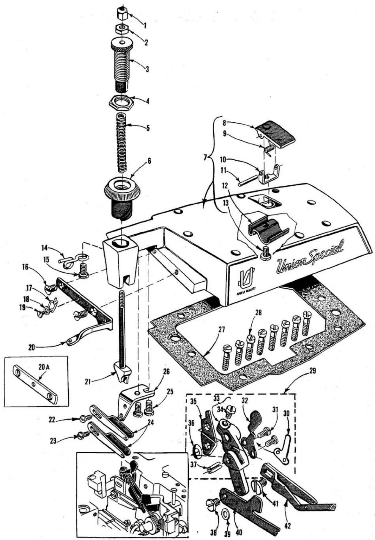
Technical diagram of a mechanical assembly with numbered components and exploded view, likely for engineering or manufacturing documentation.MAIN FRAME, MISCELLANEOUS COVERS AND PLATES
| Ref. No. | Part No. | Description | Amt. Req. |
| 1 | 22657 D-12 | Screw, for cloth plate---- | 1 |
| 2 | 22569 | Screw, for cloth plate stud---- | 1 |
| 3 | 39501 K | Cloth Plate Stud---- | 1 |
| 4 | 39534 R | Feed Bar Oil Shield---- | 1 |
| 5 | 90 | Screw, for feed bar oil shield---- | 1 |
| 6 | 667 H-16 | Dowel Pin, for eyelet bracket---- | 1 |
| 7 | 667 D-8 | Dowel Pin, for top cover---- | 2 |
| 8 | 39594 R | Oil Collector Plate---- | 1 |
| 9 | 22565 | Screw, for upper looper thread tube assembly and upper looper rocker shaft---- | 2 |
| 9A | 22565 S | Spot Screw, for upper looper rocker shaft---- | 1 |
| 9B | 22569 K | Screw, for oil sight gauge---- | 1 |
| 10 | 22569 D | Screw, for oil collector plate---- | 1 |
| 11 | 22571 E | Magnetic Oil Drain Plug---- | 1 |
| 12 | 660-243 | Oil Gauge Seal Ring---- | 1 |
| 13 | 39593 H | Oil Sight Gauge---- | 1 |
| 14 | 22894 AE | Screw, for lower looper drive lever shaft---- | 2 |
| 22894 AE | Screw, for lower looper bar driving lever shaft---- | 2 | |
| 15 | 22569 D | Screw, for chip guard---- | 2 |
| 16 | 29477 GW | Upper Looper Thread Tube Assembly, for Styles 39600 FA, FB---- | 1 |
| 16A | 29477 HJ | Upper Looper Thread Tube Assembly, for Styles 39600 FP, FQ, FR, FS---- | 1 |
| 17 | 39568 G | Thread Tube, for No. 29477 GW---- | 1 |
| 17A | 39568 P | Thread Tube, for No. 29477 HJ---- | 1 |
| 18 | 39568 J | Thread Tube Tension Spring---- | 1 |
| 19 | 22743 | Screw, for thread tube tension spring---- | 1 |
| 20 | 22824 | Screw, for oil filter screen---- | 2 |
| 21 | 39594 G | Oil Filter Screen---- | 1 |
| 22 | 39594 H | Oil Strainer---- | 1 |
| 23 | 39668 R | Looper Thread Eyelet---- | 1 |
| 24 | 53678 N | Washer, for looper thread eyelet screw---- | 1 |
| 25 | 22562 A | Screw, for looper thread eyelet---- | 1 |
| 26 | 86 X | Screw, for feed mechanism cover---- | 1 |
| 27 | 41071 G | Nut, for feed mechanism cover screw---- | 1 |
| 28 | 39582 DA | Feed Mechanism Cover---- | 1 |
| 29 | 39501 DF | Cloth Plate, for semi or fully submerged installation---- | 1 |
| 30 | 39578 F | Cloth Plate Fabric Guard---- | 1 |
| 31 | 138 | Screw, for cloth plate fabric guard---- | 2 |
| 32 | 39532 A | Cloth Plate Latch Spring---- | 1 |
| 33 | 90 | Screw, for cloth plate latch spring---- | 2 |
| 34 | 39678 AB | Chip Guard Assembly---- | 1 |
| 35 | 660-210 | Retaining Ring---- | 1 |
| 36 | 39878 C | Hinge Pin---- | 1 |
| 37 | 39678 U | Chip Guard Base---- | 1 |
| 38 | 39158 U | Spring---- | 1 |
| 39 | 43443 Q | Nut, for hinge pin---- | 2 |
| 40 | 39678 AC | Chip Guard Cover---- | 1 |
| 41 | 39582 F | Bottom Cover and Base Plate Extension---- | 1 |
| 42 | 22653 D-4 | Screw, for bottom cover and base plate extension---- | 2 |
| 43 | 39593 D | Oil Gauge Indicator---- | 1 |
| 44 | 39593 C | Oil Gauge Float---- | 1 |
| 45 | 39582 Y | Bottom Cover Gasket---- | 1 |
| 46 | 22569 | Screw, for bottom cover---- | 14 |
| 47 | 39582 XD | Bottom Cover---- | 1 |
| 48 | 39595 | Mounting Isolator, rubber---- | 4 |
| 49 | 22586 R | Screw, for bottom cover---- | 1 |
text_image
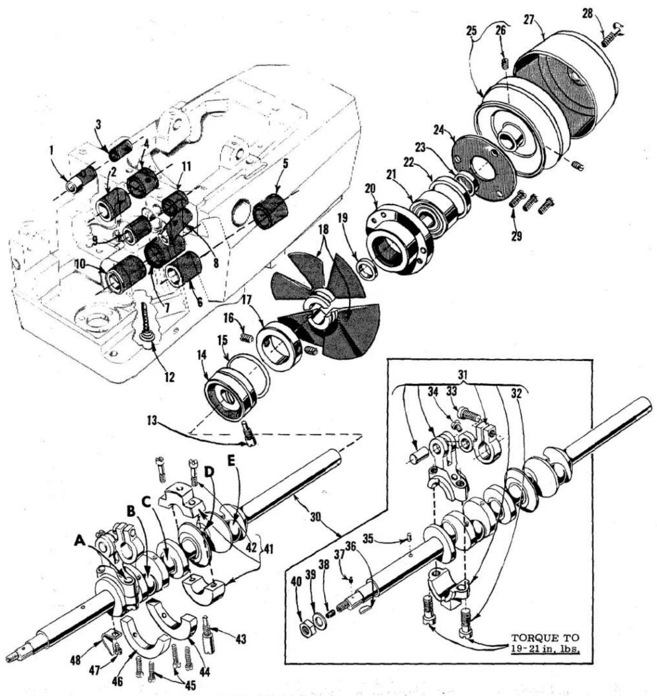
Technical diagram of a mechanical assembly with numbered parts and torque specifications for 19-21 inches.CRANKSHAFT MECHANISM AND BUSHINGS
| Ref. No. | Part No. | Description | Amt. Req. |
| 1 | 39555 E | Foot Lifter Shaft Bushing, left | 1 |
| 2 | 39573 K | Upper Knife Driving Arm Bushing, left | 1 |
| 3 | 39555 N | Foot Lifter Shaft Bushing, right | 1 |
| 4 | 39573 AA | Upper Knife Driving Arm Bushing, right | 1 |
| 5 | 39644 C | 401 Looper Drive Shaft Bushing, right | 1 |
| 6 | 39644 S | 401 Looper Drive Shaft Bushing, left | 1 |
| 7 | 39590 T | Crankshaft Bushing, inner left | 1 |
| 8 | 39544 L | Lower Looper Bar Bushing | 1 |
| 9 | 39552 U | Needle Driving Arm Crank Bushing, left | 1 |
| 10 | 39590 | Crankshaft Bushing, left | 1 |
| 11 | 39552 P | Needle Driving Arm Crank Bushing, right | 1 |
| 12 | 666-94 | Oil Wick and Spring | 1 |
| 13 | 39690 A | Stud, for crankshaft bearing | 1 |
| 14 | 39690 | Crankshaft Bearing, inner right | 1 |
| 15 | 660-443 | "O" Ring, for crankshaft bearing, inner right | 1 |
| 16 | 22894 D | Screw, for fan collar | 2 |
| 17 | 39591 H | Chamber Cooling Fan Collar | 1 |
| 18 | 39591 L | Chamber Cooling Fan | 1 |
| 19 | 39590 J | Thrust Washer | 1 |
| 20 | 39590 G | Crankshaft Ball Bearing Housing | 1 |
| 21 | 660-268 | Crankshaft Ball Bearing | 1 |
| 22 | 39590 R | Ball Bearing Stop Collar | 1 |
| 23 | 39590 S | Spacer Collar | 1 |
| 24 | 39590 H | Crankshaft Ball Bearing Retaining Plate | 1 |
| 25 | 39521 G | Pulley | 1 |
| 26 | 95 | Screw, for pulley | 2 |
| 27 | 39521 D | Pulley Cap | 1 |
| 28 | 22769 B | Screw, for pulley cap | 1 |
| 29 | 22569 B | Screw, for ball bearing housing | 3 |
| 30 | 29477 KN | Crankshaft and Needle Driving Crank Assembly, for Styles 39600 FA and FB, all gauges | 1 |
| 29477 KP | Crankshaft and Needle Driving Crank Assembly, for Styles 39600 FP, FQ, FR and FS, all gauges | 1 | |
| 31 | 29477 MC | Needle Driving Arm Crank and Connecting Rod Assembly | 1 |
| 32 | 22587 M | Screw, for needle driving arm connecting rod | 2 |
| 33 | 22569 H | Screw, for needle driving arm crank | 1 |
| 34 | 22768 C | Screw, for needle driving arm connecting rod pin | 1 |
| 35 | 51-228 Blk. | Vent Plug | 1 |
| 36 | 39541 A | Feed Drive Eccentric Key | 1 |
| 37 | 30-106 Blk. | Wood Plug | 1 |
| 38 | CO67 E | Cork Plug | 1 |
| 39 | 40-46 | Washer | 1 |
| 40 | 258 | Nut | 1 |
| 41 | 39690 B | Crankshaft Split Bearing | 1 |
| 42 | 97 A | Screw, for split bearing | 2 |
| 43 | 39590 N | Stud, for split bearing | 1 |
| 44 | 39691 | Crankshaft Counterweight, right | 1 |
| 45 | 22747 B | Screw, for counterweight | 4 |
| 46 | 39591 K | Crankshaft Counterweight, left | 1 |
| 47 | 87 U | Screw, for oil splasher | 1 |
| 48 | 39594 N | Oil Splasher | 1 |

text_image
Exploded view diagram of a mechanical assembly with numbered parts and exploded viewsNEEDLE DRIVE, FEED MECHANISM AND FEED DOGS
| Ref.No. | PartNo. | Description | Amt.Req. |
| 1 | 22565 F | Screw, for feed adjusting pin | 1 |
| 2 | 39535 C | Feed Adjusting Pin | 1 |
| 3 | 39635 | Main Feed Bar Guide, left | 1 |
| 3A | 39680 | Throat Plate Support Stop | 1 |
| 3B | 93 A | Screw, for throat plate support stop | 1 |
| 4 | 53634 C | Washer, for feed bar guide screw | 2 |
| 5 | 22569 B | Screw, for main feed bar guide, left | 2 |
| 6 | 39534 | Main Feed Bar | 1 |
| 7 | 39535 J | Feed Bar Guide Block | 1 |
| 8 | 39534 GA | Differential Feed Bar | 1 |
| 9 | 39535 D | Differential Feed Bar Guide, right | 1 |
| 10 | 53634 C | Washer, for feed bar guide screw | 2 |
| 11 | 22569 B | Screw, for differential feed bar guide, right | 2 |
| 12 | 39536 B | Feed Bar Driving Stud | 2 |
| 13 | 39538 | Feed Lift Block | 1 |
| 14 | 39534 H | Differential Feed Bar Thrust Washer | 1 |
| 15 | 22569 G | Screw, for thrust washer | 3 |
| 16 | 39626 D | Differential Feed Dog, 16 teeth per inch, marked"BR"; for No. 5 1/8 gauge, all Styles | 1 |
| - | 39626 L | Differential Feed Dog, 16 teeth per inch, marked"EW"; for No. 3 1/8 gauge, Style 39600 FA | 1 |
| *39626 C | Differential Feed Dog, 14 teeth per inch, marked"BP"; for No. 5 1/8 gauge, all Styles | 1 | |
| *39626 E | Differential Feed Dog, 22 teeth per inch, marked"BS"; for No. 5 1/8 gauge, all Styles | 1 | |
| 16A | 39626 F | Differential Feed Dog, 14 teeth per inch, marked"BT"; for No. 12 3/16 gauge, Styles 39600 FP,FQ, FR and FS | 1 |
| 39626 G | Differential Feed Dog, 16 teeth per inch, marked"BU"; for No. 12 3/16 gauge, Styles 39600 FAand FB | 1 | |
| *39626 H | Differential Feed Dog, 22 teeth per inch, marked"BV"; for No. 12 3/16 gauge, all Styles | 1 | |
| 17 | 93 | Screw, for differential feed dog | 1 |
| 18 | 39605 F-5 1/8 | Main Feed Dog, 16 teeth per inch, marked "DG";for No. 5 1/8 gauge, all Styles (throat plate No.39624 F-5 1/8) | 1 |
| *39605 H-5 1/8 | Main Feed Dog, 22 teeth per inch, marked"DZ-5 1/8"; for No. 5 1/8 gauge, all Styles(throat plate No. 39624 F-5 1/8) | 1 | |
| *39605 G-5 1/8 | Main Feed Dog, 14 teeth per inch, marked"DY-5 1/8"; for No. 5 1/8 gauge, all Styles(throat plate No. 39624 F-5 1/8) | 1 | |
| 18A | 39605 G-12 3/16 | Main Feed Dog, 16 teeth per inch, marked"DY-12 3/16"; for No. 12 3/16 gauge, Styles39600 FA and FB (throat plate No. 39624 F-12 3/16) | 1 |
| 39605 F-12 3/16 | Main Feed Dog, 14 teeth per inch, marked "DH";for No. 12 3/16 gauge, Styles 39600 FP, FQ,FR and FS (throat plate No. 39624 F-12 3/16) | 1 | |
| - | 39605 F-3 1/8 | Main Feed Dog, 16 teeth per inch, marked "EY";for No. 3 1/8 gauge, Style 39600 FA (throat plateNo. 39624 F-3 1/8) | 1 |
| *39605 H-12 3/16 | Main Feed Dog, 22 teeth per inch, marked"DZ-12 3/16"; for No. 12 3/16 gauge, all Styles(throat plate No. 39624 F-12 3/16) | 1 | |
| 19 to 48 | See following page | ||
* Available as extra send and charge item.

text_image
Exploded view diagram of a mechanical assembly with numbered parts and Chinese labelsNEEDLE DRIVE, FEED MECHANISM AND FEED DOGS
| Ref.No. | PartNo. | Description | Amt.Req. |
| 1 to 18A | See preceding page | ||
| 19 | 93 A | Screw, for main feed dog | 1 |
| 20 | 39540 B-11 | Differential Feed Driving Eccentric, for Styles39600 FA and FB, all gauges | 1 |
| 39540 B-10 | Differential Feed Driving Eccentric, for Styles39600 FP, FQ, FR and FS, all gauges | 1 | |
| 21 | 39540 B-10 | Main Feed Driving Eccentric, for Styles 39600 FAand FB, all gauges | 1 |
| 39540 B-9 | Main Feed Driving Eccentric, for Styles 39600 FP,FQ, FR and FS, all gauges | 1 | |
| 22 | 39536 AF | Main Feed Bar Driving Connection | 1 |
| 23 | 40-46 | Washer, for feed driving eccentric | 1 |
| 24 | 258 | Nut, for feed driving eccentric | 1 |
| 25 | 39536 E | Nut, for feed bar driving stud | 2 |
| 26 | 39536 C | Feed Bar Driving Connection Bushing | 2 |
| 27 | 39536 AE | Differential Feed Bar Driving Connection | 1 |
| 28 | 22569 B | Screw, for fabric guard mounting bracket | 2 |
| 29 | 8372 A | Washer, for fabric guard mounting bracket | 2 |
| 30 | 39578 P | Fabric Guard Mounting Bracket | 1 |
| 31 | 87 | Screw, for fabric guard | 2 |
| 32 | 39578 M | Fabric Guard | 1 |
| 33 | 39652-5 | Needle Driving Arm, marked "E-5"; for No. 5 1/8gauge, all Styles | 1 |
| - | 39652-3 | Needle Driving Arm, marked "E-3"; for No. 3 1/8gauge, Style 39600 FA | 1 |
| - | 39652-12 | Needle Driving Arm, marked "E-12"; for No.12 3/16 gauge, all Styles | 1 |
| 34 | 28 B | Screw, for needles | 2 |
| 35 | 22519 H | Screw, for needle driving arm | 1 |
| 36 | 39663 L | Needle Thread Cam Pull-off | 1 |
| 37 | 660-207 | "O" Ring, for take-up cam | 1 |
| 38 | 39552 C | Needle Driving Arm Crank Thrust Washer | 1 |
| 38A | 39543 Y | Thrust Collar | 1 |
| 38B | 22782 A | Screw | 1 |
| 39 | 39552 R | Needle Lever Drive Shaft | 1 |
| 40 | 39594 N | Oil Splasher | 1 |
| 41 | 87 U | Screw, for oil splasher | 1 |
| 42 | 39668 P | Looper Thread Take-up Cam | 1 |
| 43 | 531 | Screw, for looper thread take-up cam | 1 |
| 44 | 22768 | Screw, for needle thread cam pull-off | 1 |
| 45 | 22784 E | Screw, for needle driving arm thread eyelet | 1 |
| 46 | 39652 B | Needle Driving Arm Thread Eyelet, for No. 5 1/8gauge, Styles 39600 FB, FQ, FS | 1 |
| - | 39652 D | Needle Driving Arm Thread Eyelet, for No. 3 1/8gauge, Style 39600 FA and No. 5 1/8 gauge,Styles 39600 FA, FP, FR | 1 |
| 46A | 39652 C | Needle Driving Arm Thread Eyelet, for No. 12 3/16gauge, Styles 39600 FB, FQ, FS | 1 |
| - | 39652 E | Needle Driving Arm Thread Eyelet, for No. 12 3/16gauge, Styles 39600 FA, FP, FR | 1 |
| 47 | 154 GAS | Needle, for 503 or 504 stitch | 1 |
| 48 | 161 GS | Needle, for 401 stitch | 1 |
* Available as extra send and charge item.
† Use screw No 77 K in the lower hole for. No. 39663 L and 22768 in upper hole.
text_image
TORQUE TO 19-21 in. lbs. TORQUE TO 19-21 in. lbs. TORQUE TO 14 in. lbs. TORQUE TO 25-26 in. lbs. TORQUE TO 19-21 in. lbs. TORQUE TO 19-21 in. lbs. TORQUE TO 19-21 in. lbs. TORQUE TO 19-21 in. lbs. TORQUE TO 19-21 in. lbs. TORQUE TO 19-21 in. lbs. TORQUE TO 19-21 in. lbs. TORQUE TO 19-21 in. lbs. TORQUE TO 36AUPPER LOOPER, SPREADER AND LOWER LOOPER DRIVING PARTS
| Ref. No. | Part No. | Description | Amt. Req. |
| 1 | 39508 A | Upper Looper, marked "CC", for all Styles, all gauges | 1 |
| 2 | 39543 | Upper Looper Holder, marked "J" | 1 |
| 3 | 22564 G | Screw, for upper looper | 1 |
| 4 | 39543 A | Upper Looper Holder Collar | 1 |
| 5 | 22 KH | Screw, for upper looper holder collar | 1 |
| 6 | 22565 H | Screw, for bushing and cam guide | 1 |
| 7 | 1025 L | Lock Screw, for bushing and cam guide screw | 1 |
| 8 | 39543 T | Cam Follower | 1 |
| * 9 | 39543 S | Upper Looper Drive Shaft Bushing and Cam Guide | 1 |
| *10 | 39543 K | Upper Looper Drive Shaft | 1 |
| 11 | 22503 F | Screw, for cam follower locking clamp | 1 |
| 12 | 39543 E | Cam Follower Locking Clamp | 1 |
| 13 | 97 | Screw, for guide fork | 2 |
| 14 | 39544 J | Guide Fork | 1 |
| 15 | 482 C | Upper Looper Drive Lever Shaft Collar | 1 |
| 16 | 22894 C | Screw, for collar | 2 |
| 17 | 22565 | Screw, for upper looper drive lever shaft | 1 |
| 18 | 39543 X | Upper Looper Drive Lever Shaft | 1 |
| 19 | 22565 S | Screw, for upper looper drive lever shaft | 1 |
| 20 | 39543 W | Upper Looper Drive Lever | 1 |
| 21 | 39543 M | Clamp Collar | 1 |
| 22 | 22562 A | Screw, for clamp collar | 1 |
| 23 | 39543 P | Thrust Washer, for upper looper drive shaft | 2 |
| 24 | 39543 U | Upper Looper Drive Lever Connecting Rod | 1 |
| 25 | 22729 D | Screw, for connecting rod assembly | 4 |
| 26 | 666-255 | Felt Plug, for Nos. 39543 U and 39644 F | 2 |
| 27 | 39594 N | Oil Splasher | 1 |
| 28 | 87 U | Screw, for oil splasher | 1 |
| 29 | 22894 AE | Screw, for lower looper or spreader bar driving lever shaft | 2 |
| 30 | 482 C | Lower Looper or Spreader Shaft Collar | 1 |
| 31 | 22894 C | Screw, for collar | 2 |
| 32 | 22894 J | Screw, for knife drive oil drip plate | 1 |
| 33 | 12982 | Nut, for knife drive oil drip plate screw | 1 |
| 34 | 39694 | Knife Drive Connecting Rod Oil Drip Plate | 1 |
| 35 | 660-206 | "O" Ring, for lower looper or spreader bar driving lever shaft | 1 |
| 36 | 39508 B | Lower Looper, for Styles 39600 FB, FQ, FS; all gauges | 1 |
| 36A | 39560 B | Lower Spreader, for Styles 39600 FA, FP, FR; all gauges | 1 |
| 37 | 39151 | Nut, for lower looper or spreader bar | 1 |
| 38 | 39544 | Lower Looper or Spreader Bar | 1 |
| 39 | 39544 U | Lower Looper or Spreader Bar Driving Lever | 1 |
| 40 | 39644 F | Lower Looper or Spreader Drive Lever Connecting Rod | 1 |
| 41 | 22729 E | Screw, for connecting rod | 2 |
| 42 | 22729 D | Screw, for connecting rod | 2 |
| 43 | 39644 R-2 | Shim, for ball joint guide fork, .002 inch thick --- as required | |
| 39644 R-5 | Shim, for ball joint guide fork, .005 inch thick --- as required | ||
| 44 | 39644 X | Ball Joint Guide Fork | 1 |
| 45 | 538 | Screw, for ball joint guide fork | 2 |
| 46 | 77 | Screw, for connecting link pin | 1 |
| 47 | 39544 B | Lower Looper or Spreader Bar Connecting Link | 1 |
| 48 | 39544 D | Lower Looper or Spreader Bar Connecting Link Pin | 2 |
| 49 | 77 | Screw, for connecting link pin | 1 |
| 50 | 39544 V | Lower Looper or Spreader Bar Driving Lever Shaft | 1 |
* The use of assembly No. 29126 EC is recommended instead of the individual parts.

text_image
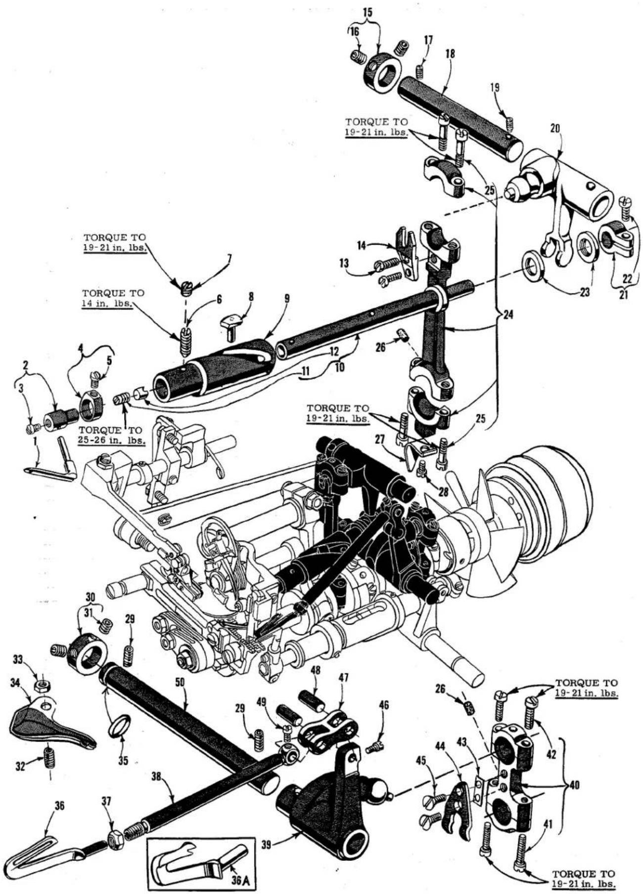
Technical diagram of a mechanical assembly with numbered parts and torque annotations in inches and poundsTHROAT PLATES, NEEDLE GUARDS, 401 STITCH LOOPER PARTS, UPPER AND LOWER KNIFE MECHANISM
| Ref.No. | PartNo. | Description | Amt.Req. |
| 1 | 39673 A | Upper Knife Driving Arm | 1 |
| 2 | 39571 A | Upper Knife Clamp Nut, for Styles 39600 FA, FB, FP and FQ, all gauges | 1 |
| 3 | 39572 B | Upper Knife Holder, for Styles 39600 FA, FB, FP and FQ, all gauges | 1 |
| 4 | 22829 | Screw, for upper knife holder, for Styles 39600 FA, FB, FP and FQ, all gauges | 1 |
| 5 | 22650 CB-4 | Set Screw, for upper knife, for Styles 39600 FA, FB, FP and FQ, all gauges | 1 |
| 6 | 39270 D | Upper Knife, narrow, for Styles 39600 FA-3 1/8 gauge and FB, all gauges | 1 |
| 6A | 39270 E | Upper Knife, wide, for Styles 39600 FA-5 1/8 and 12 3/16 gauge; FP and FQ, all gauges | 1 |
| 7 | 39571 E | Upper Knife Clamp, for Styles 39600 FA, FB, FP and FQ, all gauges | 1 |
| 8 | 39573 A | Upper Knife Driving Arm Washer | 1 |
| 9 | 39573 E | Upper Knife Driving Lever | 1 |
| 10 | 55235 D | Locking Stud, for driving lever | 1 |
| 11 | 6042 A | Washer, for driving lever | 1 |
| 12 | 55235 E | Nut, for driving lever | 1 |
| 13 | 39673 | Upper Knife Driving Lever Connecting Rod | 1 |
| 14 | 22587 E | Screw, for connecting rod | 2 |
| 15 | 39644 M | Looper Avoid Link | 1 |
| 16 | 22565 C | Set Screw, for bushing and cam guide | 1 |
| 17 | 22729 M | Spot Screw, for bushing and cam guide | 1 |
| 18 | 39644 K | Bushing and Cam Guide, for Styles 39600 FA and FB | 1 |
| - | 39644 V | Bushing and Cam Guide, for Styles 39600 FP, FQ, FR, FS | 1 |
| 19 | 39644 P | Thrust Collar | 1 |
| 20 | 98 | Screw, for thrust collar | 2 |
| 21 | 39644 U | Looper Drive Lever Auxiliary Connecting Rod | 1 |
| 22 | 22729 E | Screw, for connecting rod | 2 |
| 23 | 22729 D | Screw, for connecting rod | 2 |
| 24 | 39543 M | Clamp Collar | 1 |
| 25 | 22562 A | Screw, for clamp collar | 1 |
| 26 | 39543 P | Thrust Washer, for lower looper bar | 2 |
| 27 | 660-206 | "O" Ring, for lower looper drive lever shaft | 2 |
| 28 | 39644 N | Lower Looper Drive Lever Shaft | 1 |
| 29 | 39644 | Lower Looper Drive Lever | 1 |
| 30 | 39644 A | Lower Looper Bar (401 stitch) | 1 |
| 31 | 39644 R-2 | Shim, for ball joint guide fork, .002 inch thick as required | |
| - | 39644 R-5 | Shim, for ball joint guide fork, .005 inch thick as required | |
| 32 | 39644 X | Ball Joint Guide Fork | 1 |
| 33 | 538 | Screw, for ball joint guide fork | 2 |
| 34 | 22588 J | Screw, for lower knife clamp | 1 |
| 35 | 39550 Z | Lower Knife Clamp | 1 |
| 36 | 39550 M | Lower Knife Clamp Spring | 1 |
| 37 | 482 C | Lower Looper Drive Lever Shaft Collar | 1 |
| 38 | 22894 C | Screw, for collar | 2 |
| 39 | 39549 | Lower Knife, narrow, for Styles 39600 FA and FB | 1 |
| 39A | 39549 J | Lower Knife, wide, for Styles 39600 FP, FQ, FR and FS, all gauges | 1 |
| 40 to 78 | See following page | ||

text_image
Technical diagram of a mechanical assembly with numbered parts and labeled torque values in inches and pounds.THROAT PLATES, NEEDLE GUARDS, 401 STITCH LOOPER PARTS, UPPER AND LOWER KNIFE MECHANISM
| Ref.No. | PartNo. | Description | Amt.Req. |
| 1 to 39 A | See preceding page | ||
| 40 | 39650 | Lower Knife Holder---- | 1 |
| 41 | 39650 A | Lower Knife Clamp Screw Nut---- | 1 |
| 42 | 22729 B | Screw, for lower knife holder locating stud---- | 1 |
| 43 | 39550 C | Lower Knife Holder Locating Stud---- | 1 |
| 44 | 14077 | Nut, for locking screw---- | 1 |
| 45 | 22892 B | Locking Screw, for lower knife holder---- | 1 |
| 46 | 88 F | Screw, for needle guard---- | 1 |
| 47 | 39543 E | Needle Guard Locking Clamp---- | 1 |
| 48 | 22653 B-12 | Screw, for throat plate support bracket---- | 2 |
| 48A | 39580 F | Washer, for throat plate support bracket screw---- | 2 |
| 49 | 39580 AC | Throat Plate and Lower Knife Support Bracket---- | 1 |
| 50 | 39525 A | Needle Guard, rear, for 504 stitch needle,forStyles 39600 FB, FQ, FS, all gauges---- | 1 |
| - | 39525 J | Needle Guard, rear, for 503 stitch needle, forStyles 39600 FA, FP, FR, all gauges---- | 1 |
| 51 | 39625 B | Needle Guard, front, for 503 or 504 stitch needle---- | 1 |
| 52 | 22585 A | Screw, for 503 or 504 stitch needle guards---- | 2 |
| 53 | 90 | Screw, for 401 stitch front needle guard---- | 1 |
| 54 | 39625 D | Needle Guard, front, for 401 stitch needle, forall Styles, all gauges---- | 1 |
| 55 | 39825 C | Needle Guard, rear, for 401 stitch needle---- | 1 |
| 56 | 39624 F-5 1/8 | Throat Plate, marked 'CB', for No. 5 1/8 gauge,all Styles---- | 1 |
| 56A | 39624 F-12 3/16 | Throat Plate, marked 'CA', for No. 12 3/16 gauge,all Styles---- | 1 |
| - | 39624 F-3 1/8 | Throat Plate, marked 'CJ', for No. 3 1/8 gauge,Style 39600 FA---- | 1 |
| 57 | 22524 | Screw, for throat plate---- | 1 |
| 58 | 39550 E | Knife Holder Spring---- | 1 |
| 59 | 39644 E | Looper Holder, for 401 stitch looper---- | 1 |
| 60 | 22653 J-4 | Screw, for looper holder---- | 1 |
| 61 | 22564 D | Screw, for 401 stitch looper---- | 1 |
| 62 | 39608 D | Looper, marked "CX", for 401 stitch, all Styles---- | 1 |
| 63 | 22503 F | Screw, for cam follower locking clamp---- | 1 |
| 64 | 39543 E | Cam Follower Locking Clamp---- | 1 |
| 65 | 39644 W | Lower Looper Bar Sleeve---- | 1 |
| 66 | 39644 L | Cam Follower---- | 1 |
| 67 | 22775 | Screw, for looper avoid link---- | 1 |
| 68 | 41336 C | Looper Avoid Link Pin---- | 1 |
| 69 | 22781 | Screw, for looper avoid link pin---- | 1 |
| 70 | 39678 P | Chip Deflector, for Styles 39600 FA and FB, allgauges---- | 1 |
| 71 | 187 A | Screw, for chip deflector---- | 1 |
| 72 | 39571 C | Upper Knife Clamp Stud, for Styles 39600 FR andFS, all gauges---- | 1 |
| 73 | 39572 A | Upper Knife Holder Block, for Styles 39600 FRand FS, all gauges---- | 1 |
| 74 | 22738 | Screw, for upper knife clamp stud---- | 1 |
| 75 | 39570 K | Upper Knife, for Styles 39600 FR and FS, all gauges-- | 1 |
| 76 | 39571 F | Upper Knife Clamp, for Styles 39600 FR and FS,all gauges---- | 1 |
| 77 | 39571 B | Upper Knife Chain Guard, for Styles 39600 FR andFS, all gauges---- | 1 |
| 78 | 14077 | Nut, for upper knife clamp stud---- | 1 |
text_image
Exploded view diagram of a Union Special device with numbered parts and exploded viewsTOP COVER, EYELETS AND PRESSER SPRING PARTS
| Ref. No. | Part No. | Description | Amt. Req. |
| 1 | 39557 B | Presser Spring Plunger Cap Nut | 1 |
| 2 | 39557 E | Presser Spring Plunger Lock Nut | 1 |
| 3 | 39557 C | Presser Spring Plunger Adjusting Screw | 1 |
| 4 | 39557 F | Lock Nut, for plunger adjusting screw | 1 |
| 5 | 39557 | Presser Spring | 1 |
| 6 | 39556 A | Presser Foot Release Bushing | 1 |
| 7 | 39582 AJ | Top Cover | 1 |
| 8 | 39582 AF | Oil Filler Cover | 1 |
| 9 | 39582 V | Spring, for oil filler cover | 1 |
| 10 | 39582 AG | Hinge Bracket | 1 |
| 11 | 51-103 Blk. | Hinge Pin | 1 |
| 12 | 39582 W | Oil Guard | 1 |
| 13 | 22562 A | Screw, for hinge bracket | 1 |
| 14 | 39658 | Needle Thread Eyelet, for Styles 39600 FB, FQ and FS | 1 |
| 15 | 22849 A | Screw, for needle thread eyelet | 1 |
| 16 | 22757 E | Screw, for top cover needle thread eyelet | 2 |
| 17 | 51758 | Needle Thread Eyelet | 1 |
| 18 | 53678 N | Washer, for needle thread eyelet screw | 1 |
| 19 | 90 | Screw, for needle thread eyelet | 1 |
| 20 | 39663 J | Top Cover Needle Thread Eyelet, for Styles 39600 FB, FQ and FS, all gauges | 1 |
| 20A | 39663 R | Top Cover Needle Thread Eyelet bracket, for Styles 39600 FA, FP and FR, all gauges | 1 |
| 21 | 39557 A | Presser Spring Plunger | 1 |
| 22 | 87 U | Screw, for needle thread pull-off eyelet, for Styles 39600 FB, FQ and FS | 1 |
| 23 | 87 U | Screw, for needle thread pull-off eyelet, for all Styles | 1 |
| 24 | 39663 H | Needle Thread Pull-off Eyelet, for Styles 39600 FA, FP and FR | 1 |
| 39663 H | Needle Thread Pull-off Eyelet, for Styles 39600 FB, FQ and FS | 2 | |
| 25 | 22569 C | Screw, for top cover eyelet bracket | 2 |
| 26 | 39663 K | Top Cover Eyelet Bracket | 1 |
| 27 | 39582 AE | Top Cover Gasket | 1 |
| 28 | 22541 | Screw, for top cover | 8 |
| 29 | 39668 C | Eyelet Bracket Assembly | 1 |
| 30 | 39668 K | Latch Spring Stop Plate | 1 |
| 31 | 605 | Screw, for latch spring | 2 |
| 32 | 39668 G | Latch Spring | 1 |
| 33 | 39668 L | Eyelet Bracket | 1 |
| 34 | 22570 A | Screw, for eyelet bracket | 1 |
| 35 | 39668 F | Arm | 1 |
| 36 | 39668 H | Spring Washer, for arm | 1 |
| 37 | 660-219 N | Roll Pin, for arm | 1 |
| 38 | 22570 B | Screw, for cast-off blade | 1 |
| 39 | 53634 C | Washer, for cast-off blade screw | 1 |
| 40 | 39668 N | Cast-off Blade | 1 |
| 41 | 22829 | Screw, for take-up eyelet | 1 |
| 42 | 39668 M | Take-up Eyelet | 1 |

text_image
Technical diagram of a mechanical assembly with numbered parts and exploded views, including labeled parts and component numbers.PRESSER FEET, FOOT LIFTER PARTS, THREAD TENSION AND MISCELLANEOUS EYELETS
| Ref.No. | PartNo. | Description | Amt.Req. |
| 1 | 39855 | Foot Lifter Lever | 1 |
| 2 | 39555 B | Foot Lifter Lever Spring | 1 |
| 3 | 39555 D | Foot Lifter Intermediate Lever | 1 |
| 4 | 660-142 | Cotter Pin, for connecting link | 2 |
| 5 | 39555 F | Foot Lifter Lever Connecting Link | 1 |
| 6 | 39555 C | Foot Lifter Lever Arm | 1 |
| 7 | 12538 | Lock Nut, for lever arm | 2 |
| 8 | 22597 E | Screw, for lever arm | 2 |
| 9 | 627 | Screw, for lever arm | 1 |
| 10 | 22566 B | Screw, for foot lifter lever | 1 |
| 11 | 12865 | Thrust Collar, for foot lifter lever shaft | 1 |
| 12 | 88 | Screw, for thrust collar | 2 |
| 13 | 39655 | Foot Lifter Lever Shaft | 1 |
| 14 | 258 A | Nut, for presser arm screw | 1 |
| 15 | 22791 H | Screw, for presser arm | 1 |
| 16 | 39656 B | Presser Arm | 1 |
| 17 | 39656 A | Chain Cutting Knife, marked "AC" | 1 |
| 18 | 605 | Screw, for chain cutting knife | 1 |
| 19 | 39592 Y | Lower Looper Tension Nut, black, for Styles 39600 FB, FQ and FS | 1 |
| 39592 Z | Upper Looper Tension Nut, yellow | 1 | |
| 39592 AA | Overedge Needle Tension Nut, green | 1 | |
| 39592 AB | 401 Stitch Looper Tension Nut, blue | 1 | |
| 39592 AC | 401 Stitch Needle Tension Nut, red | 1 | |
| 20 | 39592 AK | Tension Spring Ferrule | 4 or 5 |
| 21 | 39592 AR-2 | Tension Spring, for 401 stitch looper, all Styles | 1 |
| 39592 AR-4 | Tension Spring, for 401 stitch needle and 503 stitch looper on Styles 39600 FA, FP and FR, all gauges | 2 | |
| 39592 AR-4 | Tension Spring, for needles and 504 stitch loopers on Styles 39600 FB, FQ and FS, all gauges | 4 | |
| 39592 AR-8 | Tension Spring, for 503 stitch needle on Styles 39600 FA, FP and FR, all gauges | 1 | |
| 22 | 39592 AD | Thread Tension Disc | 8 or 10 |
| 23 | 39592 AF | Tension Disc Felt | 4 or 5 |
| 24 | 39592 AL | Thread Tension Post | 4 or 5 |
| 25 | 8372 A | Washer, for thread tension post | 4 or 5 |
| 26 | 22806 A | Screw, for tension post mounting bracket | 1 |
| 27 | 39592 AH | Nut, for thread tension post | 4 or 5 |
| 28 | 39592 AG-5 | Tension Post Mounting Bracket | 1 |
| 29 | 39592 AN | Tension Post Bar | 1 |
| 30 | 22847 B | Screw, for tension post mounting bracket | 1 |
| 31 | 73 X | Screw, for frame thread guide | 2 |
| 32 | 39668 W | Frame Thread Guide, for lower looper thread, for Styles 39600 FB, FQ and FS, all gauges | 1 |
| 33 to 566 | See following page | ||

text_image
Technical diagram of a mechanical assembly with numbered parts and exploded views, including labeled parts like 'Union Speed' and various assembly configurations.PRESSER FEET, FOOT LIFTER PARTS, THREAD TENSION AND MISCELLANEOUS EYELETS
| Ref.No. | PartNo. | Description | Amt.Req. |
| 1 to 32 | See preceding page | ||
| 33 | 376 A | Screw, for looper thread eyelet, Styles 39600 FA, FP and FR---- | 1 |
| - | 376 A | Screw, for looper thread eyelet, Styles 39600 FB, FQ and FS---- | 2 |
| 34 | 39568 E | Auxiliary Upper Looper Thread Eyelet, for all Styles---- | 1 |
| 35 | 39568 L | Upper Looper Thread Eyelet, for all Styles---- | 1 |
| 36 | 39568 B | Lower Looper Thread Eyelet, for Styles 39600 FB, FQ and FS,all gauges---- | 1 |
| 37 | 43139 A | Nut, for looper thread eyelet screw, for Styles 39600 FA, FPand FR---- | 1 |
| - | 43139 A | Nut, for looper thread eyelet screw, for Styles 39600 FB, FQand FS---- | 2 |
| 38 | 22569 B | Screw, for eyelet mounting bracket---- | 1 |
| 39 | 39568 D | Looper Thread Eyelet Mounting Bracket---- | 1 |
| 40 | 39620 C-5 1/8 | Presser Foot, for No. 5 1/8 gauge, Styles 39600 FA and FB---- | 1 |
| - | 39620 C-12 3/16 | Presser Foot, for No. 12 3/16 gauge, Styles 39600 FA and FB---- | 1 |
| 41 | 39630 G | Presser Foot Shank, marked "D", for No. 5 1/8 gauge---- | 1 |
| - | 39630 J | Presser Foot Shank, marked "E", for No. 12 3/16 gauge---- | 1 |
| 42 | 22781 | Clamp Screw---- | 1 |
| 43 | 39630 AC | Spring---- | 1 |
| 44 | 39630 L | Lock Nut---- | 1 |
| 45 | 22799 U | Hinge Screw, for presser foot bottom---- | 1 |
| 46 | 39630 F-5 1/8 | Presser Foot Bottom, marked "AK-5 1/8", for No. 5 1/8gauge---- | 1 |
| - | 39630 F-12 3/16 | Presser Foot Bottom, marked "AK-12 3/16", for No.12 3/16 gauge---- | 1 |
| 47 | 39630 M | Hinge Screw, for needle hole section---- | 1 |
| 48 | 39630 H | Needle Hole Section, marked "AT", for No. 5 1/8 gauge---- | 1 |
| - | 39630 K | Needle Hole Section, marked "AR", for No. 12 3/16 gauge---- | 1 |
| 49 | 39620 F-5 1/8 | Presser Foot, for No. 5 1/8 gauge, Styles 39600 FP and FQ---- | 1 |
| - | 39620 F-12 3/16 | Presser Foot, for No. 12 3/16 gauge, Styles 39600 FP and FQ---- | 1 |
| - | 39620 F-3 1/8 | Presser Foot, for No. 3 1/8 gauge, Style 39600 FA---- | 1 |
| 49A | 39620 G-5 1/8 | Presser Foot, bottom marked "BL", for No. 5 1/8 gauge,Styles 39600 FR and FS---- | 1 |
| - | 39620 G-12 3/16 | Presser Foot, bottom marked "BK", for No. 12 3/16 gauge,Styles 39600 FR and FS---- | 1 |
| 50 | 39630 W | Presser Foot Shank, marked "G", for No. 5 1/8 gauge---- | 1 |
| - | 39630 AA | Presser Foot Shank, marked "L", for No. 3 1/8 gauge---- | 1 |
| - | 39630 X | Presser Foot Shank, marked "F", for No. 12 3/16 gauge---- | 1 |
| 51 | 22781 | Clamp Screw---- | 1 |
| 52 | 39630 L | Lock Nut---- | 1 |
| 53 | 39630 AB | Spring---- | 1 |
| 54 | 22799 Y | Hinge Screw, for presser foot bottom---- | 1 |
| 55 | 39630 T-5 1/8 | Presser Foot Bottom, marked "BL", for No. 5 1/8 gauge---- | 1 |
| - | 39630 T-3 1/8 | Presser Foot Bottom, marked "BP", for No. 3 1/8 gauge---- | 1 |
| - | 39630 T-12 3/16 | Presser Foot Bottom, marked "BK", for No. 12 3/16gauge---- | 1 |
| 56 | 39678 X | Chip Deflector, marked "A", for No. 3 1/8 gauge, Style39600 FA, for No. 5 1/8 gauge, Styles 39600 FP and FQ---- | 1 |
| - | 39678 Y | Chip Deflector, marked "B", for No. 12 3/16 gauge, Styles39600 FP and FQ---- | 1 |
| 56A | 39678 Z | Finger Guard, marked "C", for Styles 39600 FR and FS---- | 1 |
| 57 | 22768 B | Screw, for chip deflector or finger guard---- | 1 |
| 58 | 39630 M | Hinge Screw, for needle hole section---- | 1 |
| 59 | 39630 U | Needle Hole Section, marked "AV", for No. 5 1/8 gauge---- | 1 |
| - | 39630 Z | Needle Hole Section, marked "AZ", for No. 3 1/8 gauge---- | 1 |
| - | 39630 V | Needle Hole Section, marked "AU", for No. 12 3/16 gauge---- | 1 |
| *60 | 29480 LG | Rear Presser Foot Hold Down Kit---- | 1 |
| 61 | J87 J | Screw, for presser foot hold down wire---- | 1 |
| 62 | 90 | Screw, for presser foot hold down wire---- | 1 |
| 63 | 39656 E | Presser Foot Hold Down Wire Bracket---- | 1 |
| 64 | 41071 G | Nut, for screw No. 90---- | 1 |
| 65 | 77 B | Screw, for presser foot hold down wire bracket---- | 1 |
| 66 | 39656 F | Presser Foot Hold Down Wire---- | 1 |
* Available as an extra send and charge item.

text_image
Technical diagram of mechanical assembly with numbered parts and labeled parts A, 1, 2, 3, 4, 5, 6, 7, 8, 9, 10, 11, 12, 13, 14, 15, 16, 17, 18, 19, 20, 21, 22, 23, 24, 25, 26, 27, 28, 29, 30, 31, 32, 33, 34, 35, 36, 37, 38, 39THREAD STAND AND ACCESSORIES
| Ref.No. | PartNo. | Description | Amt.Req. |
| 1 | 21101 H-4 | Thread Stand, complete, for 4 cones, for Styles39600 FA, FP and FR | 1 |
| †1A | Thread Stand, complete, for 6 cones, for Styles39600 FB, FQ and FS | 1 | |
| 2 | 21114 S-4 | Lead Eyelet, for No. 21101 H-4 | 1 |
| - | 21114 AL-5 | Lead Eyelet, for 5 threads | 1 |
| 3 | 258 A | Nut | 8 or 10 |
| 4 | 652-16 | Washer | 4 or 5 |
| 5 | 21114 | Spool Seat Disc | 4 or 5 |
| 6 | 21114 W | Spool Pin | 4 or 5 |
| 7 | 21104 V | Pad, for thread cone | 4 or 5 |
| 8 | 21114 H-4 | Eyelet Support, for No. 21101 H-4 | 1 |
| - | 21114 H-6 | Eyelet Support, for 6 threads | 1 |
| 9 | 22651 CD-4 | Screw | 1 |
| 10 | 21104 B-24 | Thread Stand Rod | 1 |
| 11 | 21114 D-4 | Spool Seat Support, for No. 21101 H-4 | 1 |
| - | 21114 D-6 | Spool Seat Support, for 6 threads | 1 |
| 12 | 22651 CD-5 | Screw | 2 |
| 13 | 21104 H | Nut | 1 |
| 14 | 652-16 | Washer | 1 |
| 15 | 21114 U | Lead Eyelet Ball Split Socket | 2 |
| 16 | 21114 A | Thread Stand Base | 1 |
| 17 | 22651 CD-4 | Screw | 1 |
| 18 | 22810 | Clamp Screw | 1 |
| 19 | 21114 T | Lead Eyelet Socket Ball | 1 |
| 20 | 22651 CD-4 | Screw | 2 |
| 21 | 421 D-34 | Foot Lifter Treadle Chain, 34 inches long | 1 |
| 22 | 21388 AU | Socket Wrench, for 3/8 inch hexagonal nut holdingfeed eccentric | 1 |
| 23 | 21388 W | Wrench, curved double end, 9/32 inch opening | 1 |
| 24 | 21227 BF | Feed Eccentric Extractor Hook | 1 |
| *25 | 21209 K | Hexagon Socket Bit, 7/64 inch hexagonal (for usewith handle No. 21209 G) | 1 |
| *26 | 21225-1/16 | Looper Gauge, 1/16 inch, for 401 stitch | 1 |
| * - | 21225-1/8 | Looper Gauge, 1/8 inch, for 503 or 504 stitch | 1 |
| 27 | 660-272 | Thread Tweezers | 1 |
| 28 | 21207 B | Screwdriver, 1/8 inch diameter | 1 |
| 29 | 660-264 | "S" Hook, for treadle chain | 2 |
| 30 | WR64 | Wrench, 3/32 inch hexagonal | 1 |
| 31 | WR70 | Wrench, 7/64 inch hexagonal | 1 |
| *32 | 29481 J | Edge Guide Assembly | 1 |
| 33 | 22569 C | Screw, for edge guide mounting bracket | 2 |
| 34 | 604 | Screw, for edge guide | 2 |
| 35 | 39503 A | Edge Guide | 1 |
| 36 | 39603 A | Edge Guide Swinging Arm | 1 |
| 37 | 12957 E | Spring Washer | 1 |
| 38 | 22758 E | Screw, for edge guide swinging arm | 1 |
| 39 | 39603 | Edge Guide Mounting Bracket | 1 |
* Available as extra send and charge item.
† Number for complete thread stand not available, order component parts.
NUMERICAL INDEX OF PARTS
| Part No. | Page No. | Part No. | Page No. | Part No. | Page No. |
| 22 KH | 31 | 21114 H-6 | 43 | 22810 | 43 |
| 28 B | 29 | 21114 S-4 | 43 | 22824 | 23 |
| 30-106 Blk | 25 | 21114 T | 43 | 22829 | 33, 37 |
| 40-46 | 25, 29 | 21114 U | 43 | 22847 B | 39 |
| 51-103 Blk | 37 | 21114 W | 43 | 22849 A | 37 |
| 51-228 Blk | 25 | 21114 AL-5 | 43 | 22892 B | 35 |
| WR64 | 43 | 21207 B | 43 | 22894 C | 31, 33 |
| CO67 E | 25 | 21209 K | 43 | 22894 D | 25 |
| WR70 | 43 | 21225-1/16 | 43 | 22894 J | 31 |
| 73 X | 39 | 21225-1/8 | 43 | 22894 AE | 23, 31 |
| 77 | 31 | 21227 BF | 43 | 29477 GW | 23 |
| 77 B | 41 | 21388 W | 43 | 29477 HJ | 23 |
| †86 X | 23 | 21388 AU | 43 | 29477 KN | 25 |
| 87 | 29 | 22503 F | 31, 35 | 29477 KP | 25 |
| 87 U | 25, 29, 31, 37 | 22519 H | 29 | 29477 MC | 25 |
| 22524 | 35 | 29480 LG | 41 | ||
| J87 J | 41 | 22541 | 37 | 29481 J | 43 |
| 88 | 39 | 22562 A | 23, 31, 33, 37 | 39151 | 31 |
| 88 F | 35 | 39158 U | 23 | ||
| 90 | 23, 35, 37, 41 | 22564 D | 35 | 39270 D | 33 |
| 22564 G | 31 | 39270 E | 33 | ||
| 93 | 27 | 22565 | 23, 31 | 39501 K | 23 |
| 93 A | 27, 29 | 22565 C | 33 | 39501 DF | 23 |
| 95 | 25 | 22565 F | 27 | 39503 A | 43 |
| 97 | 31 | 22565 H | 31 | 39508 A | 31 |
| 97 A | 25 | 22565 S | 23, 31 | 39508 B | 31 |
| 98 | 33 | 22566 B | 39 | 39521 D | 25 |
| 138 | 23 | 22569 | 23 | 39521 G | 25 |
| 154 GAS | 29 | 22569 B | 25, 27, 29, 41 | 39525 A | 35 |
| 161 GS | 29 | 39525 J | 35 | ||
| 187 A | 35 | 22569 C | 37, 43 | 39532 A | 23 |
| 258 | 25, 29 | 22569 D | 23 | 39534 | 27 |
| 258 A | 39, 43 | 22569 G | 27 | 39534 H | 27 |
| 376 A | 41 | 22569 K | 23 | 39534 R | 23 |
| 421 D-34 | 43 | 22570 A | 37 | 39534 GA | 27 |
| 482 C | 31, 33 | 22570 B | 37 | 39535 C | 27 |
| 531 | 29 | 22571 E | 23 | 39535 D | 27 |
| 538 | 31, 33 | 22585 A | 35 | 39535 J | 27 |
| 604 | 43 | 22586 R | 23 | 39536 B | 27 |
| 605 | 37, 39 | 22587 E | 33 | 39536 C | 29 |
| 627 | 39 | 22587 M | 25 | 39536 E | 29 |
| 652-16 | 43 | 22588 J | 33 | 39536 AE | 29 |
| 660-142 | 39 | 22596 H | 25 | 39536 AF | 29 |
| 660-206 | 31, 33 | 22597 E | 39 | 39538 | 27 |
| 660-207 | 29 | 22650 CB-4 | 33 | 39540 B-9 | 29 |
| 660-210 | 23 | 22651 CD-4 | 43 | 39540 B-10 | 29 |
| 660-219 N | 37 | 22651 CD-5 | 43 | 39540 B-11 | 29 |
| 660-243 | 23 | 22653 B-12 | 35 | 39541 A | 25 |
| 660-264 | 43 | 22653 D-4 | 23 | 39543 | 31 |
| 660-268 | 25 | 22653 J-4 | 35 | 39543 A | 31 |
| 660-272 | 43 | 22657 D-12 | 23 | 39543 E | 31, 35 |
| 666-94 | 25 | 22729 B | 35 | 39543 K | 31 |
| 666-255 | 31 | 22729 D | 31, 33 | 39543 M | 31, 33 |
| 667 D-8 | 23 | 22729 E | 31, 33 | 39543 P | 31, 33 |
| 667 H-16 | 23 | 22729 M | 33 | 39543 S | 31 |
| 1025 L | 31 | 22738 | 35 | 39543 T | 31 |
| 6042 A | 33 | 22743 | 23 | 39543 U | 31 |
| 8372 A | 29, 39 | 22747 B | 25 | 39543 W | 31 |
| 12538 | 39 | 22757 E | 37 | 39543 X | 31 |
| 12865 | 39 | 22758 E | 43 | 39543 Y | 29 |
| 12957 E | 43 | 22768 | 29 | 39544 | 31 |
| 12982 | 31 | 22768 B | 41 | 39544 B | 31 |
| 14077 | 35 | 22768 C | 25 | 39544 D | 31 |
| 21101 H-4 | 43 | 22769 B | 25 | 39544 J | 31 |
| 21104 B-24 | 43 | 22775 | 35 | 39544 L | 25 |
| 21104 H | 43 | 22781 | 35, 41 | 39544 U | 31 |
| 21104 V | 43 | 22782 A | 29 | 39544 V | 31 |
| 21114 | 43 | 22784 E | 29 | 39549 | 33 |
| 21114 A | 43 | 22791 H | 39 | 39549 J | 33 |
| 21114 D-4 | 43 | 22799 U | 41 | 39550 C | 35 |
| 21114 D-6 | 43 | 22799 Y | 41 | 39550 E | 35 |
| 21114 H-4 | 43 | 22806 A | 39 | 39550 M | 33 |
| +77 K | 29 | ||||
| *660-443 | 25 |
NUMERICAL INDEX OF PARTS
| Part No. | Page No. | Part No. | Page No. | Part No. | Page No. |
| 39550 Z | 33 | 39592 AH | 39 | 39644 K | 33 |
| 39552 C | 29 | 39644 L | 35 | ||
| 39552 P | 25 | 39592 AK | 39 | 39644 M | 33 |
| 39552 R | 29 | 39592 AL | 39 | 39644 N | 33 |
| 39552 U | 25 | 39592 AN | 39 | 39644 P | 33 |
| 39555 B | 39 | 39592 AR-2 | 39 | 39644 R-2 | 31, 33 |
| 39555 C | 39 | 39592 AR-4 | 39 | 39644 R-5 | 31, 33 |
| 39555 D | 39 | 39592 AR-8 | 39 | 39644 S | 25 |
| 39555 E | 25 | 39593 C | 23 | 39644 U | 33 |
| 39555 F | 39 | 39593 D | 23 | 39644 V | 33 |
| 39555 N | 25 | 39593 H | 23 | 39644 W | 35 |
| 39556 A | 37 | 39594 G | 23 | 39644 X | 31, 33 |
| 39557 | 37 | 39594 H | 23 | 39650 | 35 |
| 39557 A | 37 | 39594 N | 25, 29, 31 | 39650 A | 35 |
| 39557 B | 37 | 39594 R | 23 | 39652-3 | 29 |
| 39557 C | 37 | 39595 | 23 | 39652-5 | 29 |
| 39557 E | 37 | 39603 | 43 | 39652-12 | 29 |
| 39557 F | 37 | 39603 A | 43 | 39652 B | 29 |
| 39560 B | 31 | 39605 F-3 1/8 | 27 | 39652 C | 29 |
| 39568 B | 41 | 39605 F-5 1/8 | 27 | 39652 D | 29 |
| 39568 D | 41 | 39605 F-12 3/16 | 27 | 39652 E | 29 |
| 39568 E | 41 | 39605 G-5 1/8 | 27 | 39655 | 39 |
| 39568 G | 23 | 39605 G-12 3/16 | 27 | 39656 A | 39 |
| 39568 J | 23 | 39605 H-5 1/8 | 27 | 39656 B | 39 |
| 39568 L | 41 | 39605 H-12 3/16 | 27 | 39656 E | 41 |
| 39568 P | 23 | 39608 D | 35 | 39656 F | 41 |
| 39570 K | 35 | 39620 C-5 1/8 | 41 | 39658 | 37 |
| 39571 A | 33 | 39620 C-12 3/16 | 41 | 39663 H | 37 |
| 39571 B | 35 | 39620 F-3 1/8 | 41 | 39663 J | 37 |
| 39571 C | 35 | 39620 F-5 1/8 | 41 | 39663 K | 37 |
| 39571 E | 33 | 39620 F-12 3/16 | 41 | 39663 L | 29 |
| 39571 F | 35 | 39620 G-5 1/8 | 41 | 39663 R | 37 |
| 39572 A | 35 | 39620 G-12 3/16 | 41 | 39668 C | 37 |
| 39572 B | 33 | 39624 F-3 1/8 | 35 | 39668 F | 37 |
| 39573 A | 33 | 39624 F-5 1/8 | 35 | 39668 G | 37 |
| 39573 E | 33 | 39624 F-12 3/16 | 35 | 39668 H | 37 |
| 39573 K | 25 | 39668 K | 37 | ||
| 39573 AA | 25 | 39625 B | 35 | 39668 L | 37 |
| 39578 F | 23 | 39668 M | 37 | ||
| 39578 M | 29 | 39625 D | 35 | 39668 N | 37 |
| 39578 P | 29 | 39626 C | 27 | 39668 P | 29 |
| 39580 F | 35 | 39626 D | 27 | 39668 R | 23 |
| 39580 AC | 35 | 39626 E | 27 | 39668 W | 39 |
| 39582 F | 23 | 39626 F | 27 | 39673 | 33 |
| 39582 V | 37 | 39626 G | 27 | 39673 A | 33 |
| 39582 W | 37 | 39626 H | 27 | 39678 P | 35 |
| 39582 Y | 23 | 39626 L | 27 | 39678 U | 23 |
| 39582 AE | 37 | 39630 F-5 1/8 | 41 | 39678 X | 41 |
| 39582 AF | 37 | 39630 F-12 3/16 | 41 | 39678 Y | 41 |
| 39582 AG | 37 | 39630 G | 41 | 39678 Z | 41 |
| 39582 AJ | 37 | 39630 H | 41 | 39678 AB | 23 |
| 39582 DA | 23 | 39630 J | 41 | 39678 AC | 23 |
| 39582 XD | 23 | 39630 K | 41 | 39680 | 27 |
| 39590 | 25 | 39630 L | 41 | 39690 A | 25 |
| 39590 G | 25 | 39630 M | 41 | 39690 B | 25 |
| 39590 H | 25 | 39630 T-3 1/8 | 41 | 39691 | 25 |
| 39590 J | 25 | 39630 T-5 1/8 | 41 | 39694 | 31 |
| 39590 N | 25 | 39630 T-12 3/16 | 41 | 39825 C | 35 |
| 39590 R | 25 | 39630 U | 41 | 39855 | 39 |
| 39590 S | 25 | 39630 V | 41 | 39878 C | 23 |
| 39590 T | 25 | 39630 W | 41 | 39890 | 25 |
| 39591 H | 25 | 39630 X | 41 | 41071 G | 23, 41 |
| 39591 K | 25 | 39630 Z | 41 | 41336 C | 35 |
| 39591 L | 25 | 39630 AA | 41 | 43139 A | 41 |
| 39592 Y | 39 | 39630 AB | 41 | 43443 Q | 23 |
| 39592 Z | 39 | 39630 AC | 41 | 51758 | 37 |
| 39592 AA | 39 | 39635 | 27 | 53634 C | 27, 37 |
| 39592 AB | 39 | 39644 | 33 | 53678 N | 23, 37 |
| 39592 AC | 39 | 39644 A | 33 | 55235 D | 33 |
| 39592 AD | 39 | 39644 C | 25 | 55235 E | 33 |
| 39592 AF | 39 | 39644 E | 35 | ||
| 39592 AG-5 | 39 | 39644 F | 31 |
Union Special Wants to Help You Cut Sewing Machine Maintenance Costs
Union Special is offering two practical systems to help pinpoint and reduce your sewing machine maintenance costs: a record keeping system to help spot machines requiring abnormally high maintenance, and a parts inventory system to speed routine repairs. Machine Maintenance Records
Repair-prone machines or inexperienced competent operators can eat up your maintenance dollars in short order. To help spot these problems. Union Special suggests two variations of a simple maintenance record keeping system using cards provided by Union Special.
The first system utilizes a "Machine Maintenance Record" card (Form 237) for each sewing machine in a plant. When a repair is required, the card is pulled from the file and the repair date, parts used, and their cost are entered in the spaces provided and the card is refiled.

text_image
MACHINE MAINTENANCE RECORD MAKERS NAME STYLE TYPE NEEDLE BEDIAL NO.DATE PUNCH. DATE SYMBOL PART USED GOT DATE SYMBOL PART USED COST FORM 237- Machine Maintenance Record cardThe second system is normally used when more detailed information on repair costs is desired. Two record cards are used: a "Repair Request Card" (Form 234), and a "Machine Repair Record" (Form 233). When a machine requires service, the forelady or foreman fills out the top of a "Repair Request Card" and gives it to a mechanic. He fills in the time the repair work is started, the parts used and their cost,
and the completion time. This data is then transferred to the permanen: "Machine Repair Record" kept in the office.
Whichever system is used, management now has an invaluable too to reduce needless maintenance costs.
Repair Part Inventories
While record keeping tells management which machines require abnormally high maintenance, it does little to help reduce the downtime caused by routine repairs. To alleviate this situation, Union Special recommends that manufacturers establish a formal parts inventory system for each type of sewing machine they operate.
Excessive machine downtime and wasted hours by mechanics can be eliminated with an orderly in-plant inventory of the most commonly needed parts. There is no longer a need to cannibalize other machines for spare parts. Long waits for deliveries are avoided and machine downtime is kept to a minimum. The cost of a parts inventory is small when the overall savings are considered.

text_image
MACHINE REPAIR RECORD CARD MAKER NAME MAKER NAME DATE MARKER NAME PARTS USED REPAIR REQUEST CARD DATE: INFORMATION NUMBER: PACS NUMBER: RACE MANUAL NO. CREATOR NO. PARTS USED ITEMS PAGE PART NUMBER CART FORM 233- Machine Repair Record card FORM 234- Repair Request Card TIME STARTED: TIME COMPLETED: MECHANIC NO. : 1000 HORN BY: 00000000000000000000000000000000000000000000000000000000000000000000000000000000 FOM 233- MACHINE Repair Record cardFor free sample copies of the machine record cards and spare part inventory lists for a variety of the most popular machines, contact your local Union Special Representative or write direct to Union Special.
UnionSpecial®
Style 39600 FP
Suggested Minimum Spare Parts List*
| Part Number | Description | Minimum Quantity Per 5 Machines | Part Number | Description | Minimum Quantity Per 5 Machines |
| 39620 F-5-1/8 or | Presser foot | 1 | 39630 L | Lock nut for hinge screw | 2 |
| 22799 Y | Hinge screw for presser foot bottom | 2 | |||
| 39620 F-12-3/16 | Presser foot | 1 | 39549 J | Lower knife (wide) | 6 |
| 22781 | Presser foot clamp screw | 2 | 39270 E | Upper knife (wide) | 6 |
| 39630 AB | Presser foot spring | 2 | 22629 | Screw for upper knife holder | 2 |
| 39605 F-5-1/8 or | Main feed dog for 5-1/8 gauge | 1 | 22650 CB-4 | Set screw for upper knives | 2 |
| 39571 A | Upper knife clamp nut | 2 | |||
| 39605 F-12-3/16 | Main feed dog for 12-3/16 gauge | 1 | 22588 A | Screw for lower knife clamp | 2 |
| 93 A | Screw for main feed dog | 4 | 39650 A | Lower knife clamp screw nut | 2 |
| 39626 D or | Differential feed dog for 5-1/8 gauge | 1 | 39550 Z | Lower knife clamp | 2 |
| 39608 D | 401 stitch looper | 2 | |||
| 39626 F | Differential feed dog for 12-3/16 gauge | 1 | 22564 D | Screw for 401 stitch looper | 4 |
| 22653-J-4 | Screw for 401 stitch looper holder | 4 | |||
| 93 | Screw for differential feed dog | 4 | 39508 A | Upper looper (all gauges) | 2 |
| 39624 F-5-1/8 or | Throat plate 5-1/8 gauge | 1 | 22564 G | Screw for upper looper | 6 |
| 39560 B | Lower spreader (all gauges) | 2 | |||
| 39624 F-12-3/16 | Throat plate for 12-3/16 gauge | 1 | 39151 | Nut for lower spreader bar | 4 |
| 22524 | Throat plate screws | 6 | 22519 H | Clamp screw for needle driving arm | 4 |
| 154 GAS | 503 stitch needles (specify size) | 100 | 28 B | Screws for needles | 12 |
| 161 GS | 401 stitch needles (specify size) | 100 | 22784 E | Screw for thread eyelet | 4 |
| 39630 M | Hingescrew for needle hole section | 2 | 29480 LG | Kit of parts for holding rear of foot down | 1 |
| *The parts and quantities listed above are intended to assist you in setting up the initial inventory of spare parts. An efficient inventory can only be established according to actual usage. The nature of the sewing operation will determine actual usage. | 21225 1/8 | Looper gauge | 1 | ||
| 21225 1/16 | Looper gauge | 1 | |||
| 29484 | Screw assortment | 1 | |||

bar
| Company | Revenue ($M) | | :--- | :--- | | Samsung | 12.5 | | Apple | 10.8 | | Amazon | 9.2 | | Microsoft | 7.6 | | Alphabet | 6.3 | | General Motors | 5.4 | | Oppo | 4.9 | | IBM | 4.5 | | HP | 4.1 | | Sony | 3.8 | | Peacock | 3.5 | | Zillow | 3.2 | | HP | 2.9 | | IBM | 2.6 | | HP | 2.3 | | Sony | 2.1 | | IBM | 1.8 | | HP | 1.5 | | Sony | 1.3 | | IBM | 1.1 | | HP | 0.9 | | Sony | 0.7 | | IBM | 0.5 | | HP | 0.3 | | Sony | 0.2 | | IBM | 0.1 | | HP | 0.05 | | Sony | 0.03 | | IBM | 0.02 | | HP | 0.01 | | Sony | 0.005 | | IBM | 0.003 | | HP | 0.002 | | Sony | 0.001 | | IBM | 0.0005 | | HP | 0.0003 | | Sony | 0.0002 | | IBM | 0.0001 | | HP | 0.00005 | | Sony | 0.00003 | | IBM | 0.00002 | | HP | 0.00001 | | Sony | 0.000005 | | IBM | 0.000003 | | HP | 0.000002 | | Sony | 0.000001 | | IBM | 0.0000005 | | HP | 0.0000003 | | Sony | 0.0000002 | | IBM | 0.0000001 | | HP | 0.00000005 | | Sony | 0.00000003 | | IBM | 0.00000002 | | HP | 0.00000001 | | Sony | 0.00000001 | | IBM | 0.00000001 | | HP | 0.00000001 | | Sony | 0.00000001 | | IBM | 0.0000001 | | HP | 1.5 | The chart displays the annual revenue (in millions of dollars) for four companies: Samsung, Apple, Amazon, Microsoft, and Alphabet. The values are estimated based on the data provided in the code above the chart.
natural_image
World map illustration showing continents and latitude/longitude lines (no text or labels)WORLDWIDE SALES AND SERVICE
Union Special Corporation maintains sales and service facilities throughout the world. These offices will aid you in the selection of the right sewing equipment for your particular operation. Union Special Corporation representatives and service technicians are factory trained and are able to serve your needs promptly and efficiently. Whatever your location, there is a qualified representative to serve you.
Corporate Office:
One Union Special Plaza
Huntley, IL 60142
Phone: 708·669·5101
Fax: 708·669·1096
European Distribution Center:
Union Special GmbH
Raffleisenstrasse 3
D-71696 Möglingen, Germany
Tel: 49-07141-247-0
Fox: 49·7141·247·100
Brussels, Belgium
Charlotte, N.C.
Commerce, CA
El Paso, TX
Hong Kong, China
Huntley, IL
Leicester, England
Lille, France
Miami, FL
Milan, Italy
Mission, TX
Möglingen, Germany
Montreal, Quebec
Osaka, Japan
Other Representatives throughout all parts of the world.

Finest Quality
Union Special INDUSTRIAL SEWING EQUIPMENT