
61400S - Industrienähmaschine Union Special - Kostenlose Bedienungsanleitung
Finden Sie kostenlos die Bedienungsanleitung des Geräts 61400S Union Special als PDF.

| Produkttyp | Industrienähmaschine (Steppstich) |
| Marke | Union Special |
| Modell | 61400S |
| Klasse | 61400 |
| Stil | 61400 S |
| Anwendung | Anbringen von Ärmelbesätzen an Arbeits- und Hemdblusen; Oberwalzenvorschub nach hinten zur Nadel |
| Stichart | Steppstich |
| Nadelstangenhub | 1 13/64 Zoll |
| Empfohlene Nadeln | Typ 180GNS oder 180GPS (kurze Länge, Größen 028 bis 060) |
| Stichlängeneinstellung | Drucktastensteuerung mit Anzeigeskala (S bis L) |
| Transportmechanismus | Normaltransport mit kraftbetriebenem Oberwalzenvorschub nach hinten zur Nadel |
| Schmiersystem | Automatische Schmierung der unteren Hauptwelle, Transportwelle, Transportaufzugslager; plus manuelle Schmierstellen |
| Öltyp | Reines Mineralöl, Saybolt-Viskosität 200-250 Sek. bei 100°F (Union Special Spezifikation Nr. 83 oder 86) |
| Ölbehälterkapazitäten | Hauptbehälter (ca. 2x/Monat nachfüllen), Greiferölbehälter (2x/Tag prüfen), Greiferwellengetriebegehäuse (alle 6 Monate prüfen) |
| Montageart | Sockelmontage (isolierte Montage möglich) |
| Riemenart | Keilriemen Nr. 1 oder Rundriemen |
| Standardzubehör | Spulenwickler, Auffangschale, Ölablassflasche mit Klemmfeder, Kniehebelvorrichtung, Raststift, Scharnierplatten, Filzunterlagen |
| Verfügbare Tischplatten | Größen: 42x20, 48x20, 54x20, 60x20 Zoll (verschiedene Konfigurationen) |
| Sicherheitshinweise | Ölbehälter vor Betrieb füllen; Maschine nicht ohne Spulenkapsel betreiben; nur empfohlenes Öl verwenden |
| Ersatzteile | Verwenden Sie Original Union Special Teile; vollständige Teileliste und numerischer Index im Handbuch enthalten |
Häufig gestellte Fragen - 61400S Union Special
Benutzerfragen zu 61400S Union Special
0 Frage zu diesem Gerät. Beantworten Sie die, die Sie kennen, oder stellen Sie Ihre eigene.
Eine neue Frage zu diesem Gerät stellen
Laden Sie die Anleitung für Ihr Industrienähmaschine kostenlos im PDF-Format! Finden Sie Ihr Handbuch 61400S - Union Special und nehmen Sie Ihr elektronisches Gerät wieder in die Hand. Auf dieser Seite sind alle Dokumente veröffentlicht, die für die Verwendung Ihres Geräts notwendig sind. 61400S von der Marke Union Special.
BEDIENUNGSANLEITUNG 61400S Union Special

Union Special INDUSTRIAL SEWING EQUIPMENT
CATALOG NO. 83R
61400 CLASS
STREAMLINED HIGH SPEED
LOCKSTITCH MACHINES
Aid Plant Layout! Boost Production!
PEDESTAL MOUNTED MACHINES
UNION SPECIAL'S pedestal mountings for sewing heads have offered a great many advantages to manufacturers ever since they were introduced as a revolutionary new type of mounting for feed-off-the-arm machines in Classes 35700 and 35800.
In the pedestal mounted type installation, the machine is completely isolated from the base and, where table boards are used, they are completely isolated from the pedestal and from the machine, which makes for smoother, quieter operation. In various cases, the motor may be mounted to the right or to the left under the machine handwheel. Mounting of the motor to the right provides maximum space under machine for the operator.
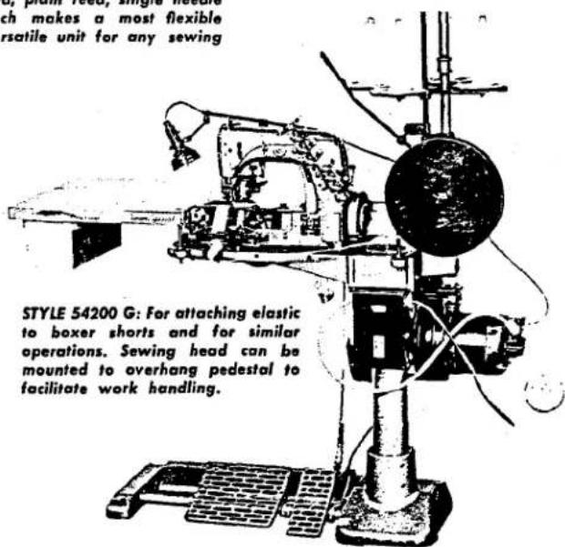
These new pedestals offer maximum flexibility, convenience, and adaptability to production lines, especially where variations in operation or garment styles are necessary from time to time. The foot treadles are adjustable laterally and the machine mounting bracket is adjustable vertically to suit the individual operator and to provide the most comfortable working position, thus reducing fatigue. The illustrations shown here are just a few of the many styles of machines that Union Special has to offer in the pedestal mounted type installation which manufacturers all over the world have found to be necessary equipment for increasing production.

CLASS 35700: This is the feed-off-the-arm felling machine for which the pedestal mounting first was developed. This type installation requires little floor space and provides large working area.
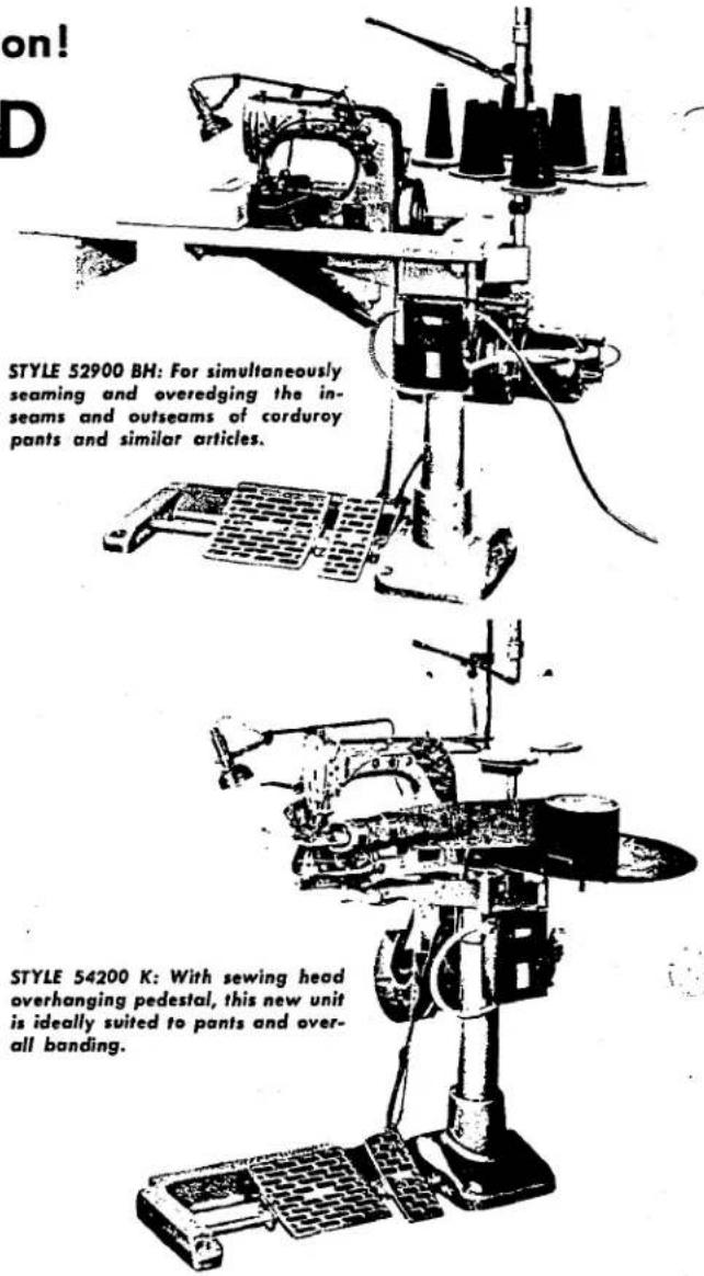
STYLE 61400 A: The pedestal mounted, plain feed, single needle Lockstitch makes a most flexible and versatile unit for any sewing plant.
Catalog No. 83 R
LIST OF PARTS AND INSTRUCTIONS
FOR
ADJUSTING AND OPERATING
Class 61400
Streamlined Lockstitch
Styles
61400 A 61400 J
61400 B 61400 N
61400 E 61400 P
61400 F 61400 R
61400 G 61400 S
61400 H 61400 AA
61400 BA
The parts listed in this catalog are furnished at list prices for repairs only.
Third Edition
Copyright 1955
By
Union Special Machine Co.
Rights Reserved in All Countries
UnionSpecial
MACHINE COMPANY
INDUSTRIAL SEWING MACHINES
CHICAGO
Printed in U.S.A.
March, 1966
(1) 2017年1月1日至2018年1月1日(含)的公司股票交易均价为4.56元/股,与前一交易日收盘价相比,涨幅为-0.97%。
(1) 2017年 ,公司与上海浦东发展银行股份有限公司签订了《关于使用部分闲置募集资金进行现金管理的协议》。
(2) 1/2 (3) 1/2 (4) 1/2 (5) 1/2 (6) 1/2 (7) 1/2 (8) 1/2 (9) 1/2 (10)
1. 2017年1月1日
(1) 本说明仅供参考。
(1) 2017年1月1日至2018年1月1日,公司与关联方累计发生关联交易的总金额为人民币4,500万元。
(1) AD = BD = 1
(1) 2017年1月1日至2018年1月1日,公司与关联方累计发生关联交易的总金额为人民币45,000万元。
(1) 1/2 (2) 1/2 (3) 1/2 (4) 1/2 (5) 1/2 (6) 1/2 (7) 1/2 (8) 1/2 (9) 1/2 (10)
(1) 2017年1月1日至2018年1月1日,公司与关联方累计发生的交易金额为人民币4,500万元。
[Non-Text]
[Non-Text]
FOREWORD
The dominating idea back of "Union Special" is to build the best industrial sewing machines in the world. The new high speed Stream-lined Lockstitch machines are a pronounced achievement along these lines. All parts are made to precision gauges insuring complete interchangeability. A few of the outstanding new features are:
-
Streamlined design. Pleasing in appearance, this natural functional design provides greater stability and ruggedness, free from difficult-to-clean recesses.
-
Simplified oiling. Automatically supplies oil to lower main shaft bearings, feed rocker and feed lift bearings and not only eliminates all oil holes in cloth plate but also does away with hand lubrication commonly required below bed plate.
-
Acceleration. The new Streamlined Lockstitch is brought to top speed in an instant - for higher productive rates and lower costs.
-
Push button control, for quick, easy adjustment of stitch length. With a stitch length indicator of the comparison type, using letters as a means of reference to predetermine stitch lengths.
It is our constant aim to furnish carefully prepared information that will enable the customer to secure all possible economies and advantages from the use of Union Specials. The following pages contain valuable operating and adjusting data and illustrate and describe the parts for Styles in Class 61400 Streamlined Lockstitch machines.
An additional catalog, containing information relative to these machines, and which will be furnished on request, is listed below:
Catalog No. 45 N Needle Manual
Union Special representatives will be found in all manufacturing centers, ready to cooperate with you to plan and estimate requirements.
UnionSpecial MACHINE COMPANY
Engineering Department
APPLICATION OF CATALOG
This catalog applies only to the standard styles of machines as listed herein. It can also be applied with discretion to the special machines in Class 61400. All references to directions, such as right and left, front and back, etc., are taken from the operator's position while seated at the machine..
IDENTIFICATION OF MACHINE
Each Union Special carries a style number which is stamped in the name plate on the machine. Style numbers are classified as standard and special. Those which are standard have one or more letters suffixed, but never contain the letter "Z". Example: "61400 A". Style numbers containing the letter "Z" are special.
Styles of machines similar in construction are grouped under a class number which differs from the style number in that it contains no letters. Example: "61400".
STYLES OF MACHINES IN CLASS 61400 STREAMLINED LOCKSTITCH
| 61400 A | For plain seaming, 1 9/64 inch needle bar travel. Accessories No. 29480 AJ included. Plain edge guide No. 61203 or 61203 A and attaching screw No. 22551 A or three-way edge guide No. 61303 E with attaching screw No. G26 will be furnished gratis when specified. All other guides and attachments are extra. (Specify feed dog, presser foot, throat plate, attachments, guides, stitches per inch, thread number, needle type and size.) |
| 61400 B | Same as Style 61400 A, except it has 1 13/64 inch needle bar travel. |
| 61400 E | Non-adjusted machine prepared to receive Columbia pinking attachment, 1 9/64 inch needle bar travel, no sewing parts included. Accessories No. 29480 AJ included. (Specify needle type and size.) (NO LONGER AVAILABLE) |
| 61400 F | Same as Style 61400 E, except it includes sewing parts and Columbia pinking attachment for plain seaming and simultaneous pinking operations on light to medium work, such as house dresses, slips, etc. (Specify needle type and size.) (NO LONGER AVAILABLE) |
| 61400 G | Non-adjusted machine prepared to receive Lewis pinking attachment, 1 9/64 inch needle bar travel, plain feed, no sewing parts included. Accessories No. 29480 AJ included. (Specify needle type and size.) (NO LONGER AVAILABLE) |
| 61400 H | Same as 61400 G, except it includes sewing parts and Lewis pinking attachment, for plain seaming and simultaneous pinking operation on light to medium work such as house dresses, slips, etc. (Specify needle type and size.) |
| 61400 J | Same as Style 61400 A, except equipped with a quick stitch change mechanism that will produce two predetermined stitch lengths by instant adjustment. |
| 61400 N | Equipped with power driven top roller feed to right of needle, 1 9/64 inch needle bar travel, for attaching collar bands to dress shirts and hemming tails of sport or dress shirts, etc. Accessories No. 29480 AJ included. (Specify feed dog, presser foot, throat plate, feed roller, guides, stitches per inch, thread number, needle type and size.) |
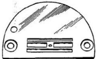
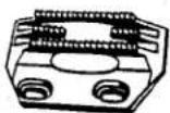
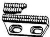
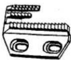
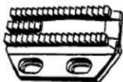
| 61400 P | Equipped with power driven top roller feed to rear of needle, 1 9/64 inch needle bar travel, for attaching sleeve facings to work and dress shirts. Accessories No. 29480 AJ included. (Specify feed dog, presser foot, throat plate, feed roller, guides, stitches per inch, thread number, needle type and size.) |
| 61400 R | Same as Style 61400 N, except it has 1 13/64 inch needle bar travel. (Specify feed dog, presser foot, throat plate, feed roller, guides, stitches per inch, thread number, needle type and size.) |
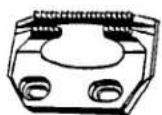
| 61400 S | Same as Style 61400 P, except it has 1 13/64 inch needle bar travel. (Specify feed dog, presser foot, throat plate, feed roller, guides, stitches per inch, thread number, needle type and size.) |
| 61400 AA | Same as Style 61400 A, except without accessories. We do furnish one extra bobbin, spool pin, two hinge studs and two No. 22585 A screws for attachment. |
| 61400 BA | Same as Style 61400 B, except without accessories. We do furnish one extra bobbin, spool pin, two hinge studs and two No. 22585 A screws for attachment. |
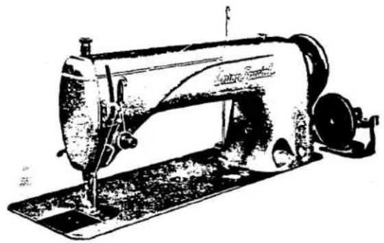
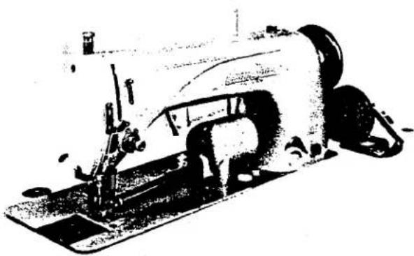
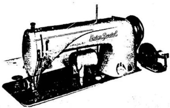
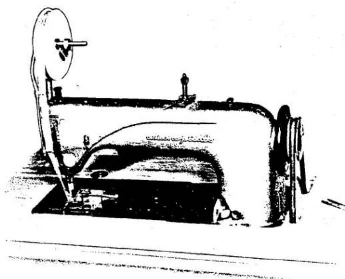
ILLUSTRATIONS OF STANDARD LOCKSTITCH MACHINES
natural_image
Line drawing of a vintage sewing machine (no text or symbols visible)61400 A 61400 B
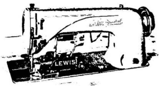
61400 G
Note: See page 81 for pinker repair parts.
natural_image
Black-and-white illustration of a vintage sewing machine (no visible text or symbols)61400 N 61400 R
natural_image
Vintage sewing machine with visible branding and mechanical components (no readable text or symbols)61400 P 61400 S
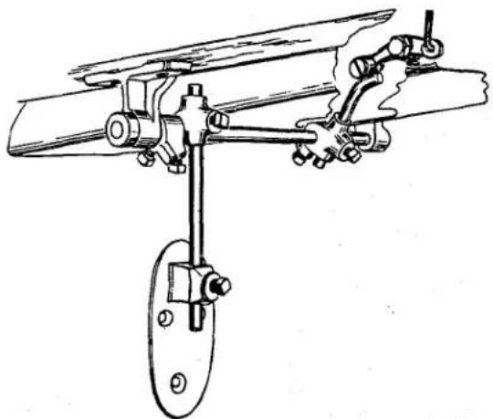
Other equipment which may be applied to Union Special Lockstitch machines is the Fowler Trimmer. This attachment is furnished by the Fowler Machine and Attachment Company, 1128 Broadway, Brooklyn, N. Y.
Your inquiries regarding this equipment will be promptly attended to. The illustration below shows the Fowler Trimmer installed on a Style 61100 C skirt taping machine.
natural_image
Line drawing of a vintage mechanical device with a circular component and base mount (no text or symbols)Fowler Trimmer
![INSTRUCTIONS FOR ASSEMBLING ACCESSORIES 29480 AJ OR 29480 CG & ISOLATORS 29480 AK ONTO TABLEBOARDS 2137INB, 2137IND (ALL LENGTHS) POSITION BRACKETS AT STENCILED LINES [61376F] [61376E] [61376C] [61376E] [61376D] [61376G] [61376H] [61376I] [61376J] [61376K] [61376L] [61376M] [61376N] [61376O] [61376P] [61376Q-16] [NA-15] * 21393 T 21393 E [NA-12] G1374 ASSEMBLY N° 61477 NA-12 NA-12A NA-15 ASSEMBLY N° 61477 666-166 21393 F TABLE BOARD 660-168 21371 NB-42,-48,-54,-60 21371 ND-42,-48,-54,-60 POSITION OIL PAN BY NAILING AT DIMPLES IN BOARD. PROPER POSITION PROVIDES DRAINING TO THE RIGHT FRONT CORNER. NOTE: PART NUMBERS ENCLOSED IN BRACKETS ARE NOT IN- CLUDED WITH ACCESSORIES 29480AT BUT ARE FUR- NISHED SEPARATELY AS 29480 AK. SC 329A 21662C 21665C 2166IP 69FD 21665 2166ID 21663C 21664 ASSEMBLY N° 21660C PERIMETER OF BED MUST CONTACT THE TWO LEATHER ISOLATORS ONLY, IF BED CONTACTS BOARD, VIBRA- TION WILL BE TRANSMITTED END OF ISOLATORS MAY BE TRIMMED TO BRING CLOTH PLATE FLUSH WITH TABLE BOARD THE TWO NAILS SECURING LEATHER ISOLATOR TO TABLE BOARD MUST BE LOW ENOUGH TO CLEAR BED * 2/393 T INCLUDED WITH 29480 CG FOR 6/900 WITH PINKER](/content/2026/06/1210933/images/f1b2d19e7f25551294ecc2da4b14c0f170de5b3f8e923b51de25e9446c1fd75f.jpg)
INSTALLING
Each machine before it leaves the factory is sewed off, inspected, and carefully packed. When the machine reaches the customer it is ready for service. Because of all the precaution taken by those who handle the machine, the customer needs only to place it in its proper position in the table and make only the ordinary settings to adapt the machine to the material he wishes to sew.
ASSEMBLY PARTS
A bag of assembly parts, consisting of one spool pin, one extra bobbin, two hinge studs, and two screws for holding miscellaneous attachments to the bed plate is packed with each machine.
After unpacking the machine assemble the spool pin (K, Fig. 3).
Push the hinge studs into position in the holes provided at the rear of the machine. The studs are slotted so that a tight fit can be easily made.
STANDARD ACCESSORIES
Also included with each machine is a box of standard accessories containing one bobbin winder assembly, one drip pan, one oil drain jar and clamp spring, one knee lifter assembly and rubber pad, one machine rest pin, two hinge plates and screws, four felt pads and necessary nails. These parts are indispensable when setting up the machine.
TABLE TOPS
Lockstitch machines are installed in table tops prepared with cut out, so that the bed plate is flush with the top of the table.
Standard table tops are available for isolated mounting on all types of installations and drives.
Isolated mounting parts are not included with table tops and must be ordered separately. The installation of isolated mounting parts is shown in (Fig. 1). For table tops not prepared for isolated mounting, felt pads are furnished with the accessories for isolating. The nails for these pads should be driven horizontally as indicated on the right end of cut-out (Fig. 1).
When assembling the hinge plates to the table tops, be sure to locate them as accurately as possible, so that the hinge studs, attached to the machine, can swing properly in the plate.
Special care should be taken that machine does not contact the sides of the cut-out at any point.
KNEE PRESS
The knee press is attached to Union Special table tops at the location designated by punch marks on the underside. For other boards locate the knee press so that the center of the shaft is 8-1/4 inches from the right side of the cut-off. The knee press assembly should appear as in (Fig. 2).
DRIP PAN
The drip pan is attached to Union Special table tops at the indentation marks on the inside of the cut-out, using the nails furnished with the accessories (Fig. 1). For other table tops, the drip pan should be set high enough to clear the knee press and low enough to clear the bottom of the machine. It should be laterally located so that it is directly under the base of the machine.
natural_image
Technical line drawing of a mechanical assembly with no visible text or symbolsFig. 2
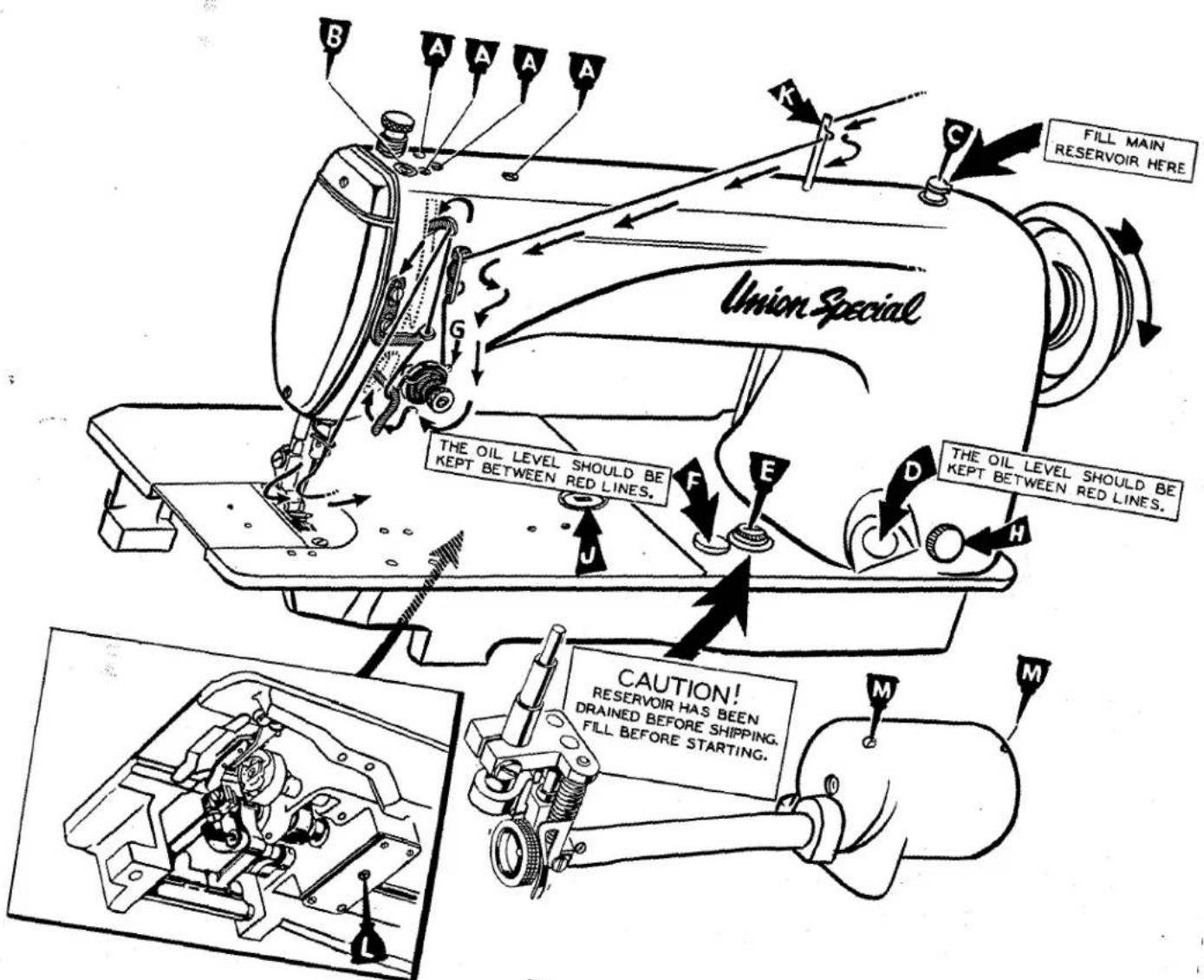
Fig. 3
BOBBIN WINDER
The bobbin winder should be secured to the table top so that its pulley will be located directly in front of the sewing machine belt and will bear against the belt when in operation. The base of the winder has two elongated attaching holes, which allows the mechanism to be moved closer to or farther away from belt as needed. The pulley of the winder, when in operation should exert only enough pressure against the belt to wind the bobbin. Regulation and operation of the bobbin winder is described under "Threading and Winding the Bobbin".
BELTS
These machines are equipped to use either No. 1 "V" or round belt.
LUBRICATION
CAUTION!!
The oil has been drained from the main reservoir, the hook shaft gear case, and the hook oil reservoir before shipment and these reservoirs must be filled before starting to operate. Lubricate machine thoroughly in accordance with instructions and run slowly for several minutes to distribute the oil to the various parts. Full speed operation can then be expected without damage.
RECOMMENDED OILS
Use a straight mineral oil of a Saybolt viscosity of 200 to 250 seconds at 100°F . in hook oil reservoir, main reservoir, and hook shaft gear case. This is equivalent to Union Special oil specification No. 83.
Stainless water white straight mineral oil of the same viscosity as that described in the preceding paragraph can be used in the hook oil reservoir, the stainless oil is Union Special specification No. 86.

natural_image
Technical line drawing of a mechanical assembly with no visible text or symbolsFig. 4
Oils conforming to specification No. 83 or 86 may also be used in the manually oiled places.
For trouble free operation, oil the machine as indicated in the diagram (Fig. 3).
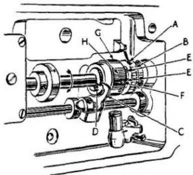
With needle bar at the top of its stroke, oil the holes (A) twice daily. In oiling hole (B), very little oil should be used and only around the outer edges of the needle bar. Do not put oil into the hole in the needle bar as it will flow out when machine is operated at high speed. A can of oil, No. 28604 J, is included with the accessories packed with the machine. It contains a sufficient quantity to fill all the reservoirs. The main reservoir is filled through oil cup (C) and the supply is usually replenished about twice a month. However, the oil level should be checked from time to time and kept between the lines on the gauge (D).
The hook oil reservoir is filled at plug screw (E) and its level should be checked twice daily and kept between the lines on the gauge (F).
The hook shaft gear case is filled at the plug screw hole (L). A quantity of oil sufficient to bring the level up to the plug screw hole, when the machine is tilted back against the rest pin, should be used. Remove plug screw and check the level of oil about every six months.
On Styles 61400 N, 61400 P, 61400 R, 61400 S, holes (M) should be oiled sparingly each day.
CAUTION!!
Do not use a compounded oil in the hook oil reservoir, feeding drive shaft gear case, or hook shaft gear case, as these oils separate and froth.
CAUTION!!
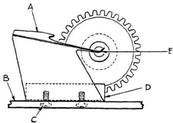
Fig. 5
Lubrication of the mechanism below the bed plate is automatically accomplished through the feed driving shaft which is tubular. Oil is introduced into the shaft at the gear end by means of an oil distributing plate (A, Fig. 5) which is secured to the large gear case cover (B) by means of two screws (C) and retaining block (D).
Should it ever become necessary to remove any of the parts from the gear case, it is imperative that the adjustment of the oil distributing plate be checked very carefully. This can be done by removing the large plug screw at the right end of the gear housing and looking through the hole. The low point of the oil distributing plate must be even with or slightly below the center of shaft (E) and just touching it. This is a very important adjustment as the functioning of the automatic lubrication of the lower part of the machine depends upon it.
NEEDLES
TYPE NUMBERS AND SIZES
Each needle has a type number and size number. The former denotes the kind of shank, point, length of groove, finish and other details. The latter denotes the largest diameter of the blade, measured in thousandths of an inch across the eye, and is stamped in the needle shank. Collectively, the type number and the size number is the complete symbol.
To have orders promptly and accurately filled, the empty package, a sample needle, or the type and size number should be given. See marks on packages. A complete order would read as follows: "1000 Needles Type 183GNS, Size 040".
Needle Types 180GNS, 180GPS are recommended for Styles 61400 B, 61400 R, 61400 S. Needle Types 183GNS, 183GPS are recommended for Styles 61400 A, 61400 E, 61400 F, 61400 G, 61400 H, 61400 N, 61400 P.
| TYPE NO. | DESCRIPTION AND SIZES |
| 180GNS | Round shank, round point, lockstitch, short length, ball eye, single groove, struck groove, short spot, ball point, chromium plated - sizes 032, 036, 040, 044, 048, 054, 060 |
| 180GPS | Round shank, round point, lockstitch, short length, ball eye, single groove, struck groove, short spot, chromium plated - sizes 028, 032, 036, 040, 044, 048, 054, 060 |
| 183GNS | Round shank, round point, lockstitch, extra short length, ball eye, single groove, struck groove, short spot, ball point, chromium plated - sizes 029, 032, 036, 040, 044 |
| 183GPS | Round shank, round point, lockstitch, extra short length, ball eye, single groove, struck groove, short spot, chromium plated - sizes 029, 032, 036, 040, 044 |
SELECTING THE SIZE OF THE NEEDLE
The strength requirement of the seam produced is largely dependent on the size of the thread employed. The quality of the work desired is largely dependent on the size of the needle employed. On heavy work, the penetration of which requires a sturdy needle, it is advisable to use a comparatively large size needle for a given size thread.
The following table shows the preferred size of needle for a given size and kind of thread. The choice, however, should give consideration to the factors referred to above, which may dictate the selection of a needle size slightly larger or smaller than the size specified.
NEEDLES (Continued)
SELECTING THE SIZE OF THE NEEDLE (Continued)
| COTTON THREAD SIZE | MERCERIZED THREAD SIZE | NEEDLE SIZE |
| 20 | - | 060 |
| 30 | B | 054 to 060 |
| 36 | A | 048 to 054 |
| 40 | A | 044 to 048 |
| 50 | O | 044 to 048 |
| 60 | OO | 040 to 044 |
| 70 | OOO | 036 to 040 |
| 80 | OOOO | 032 to 036 |
| 90 | OOOO | 032 to 036 |
| 100 | - | 028 to 032 |
OPERATOR'S INSTRUCTIONS
THREAD
While the direction of the twist in the bobbin thread is immaterial, the direction the hook rotates favors the use of a left twist thread in the needle. To determine the direction of twist grasp a short length of thread between the thumb and forefinger of both hands. Turn the thread away from you with the right hand. If the strands unwind it is a left twist; if the strands wind tighter it is a right twist.
SELECTING THE HOOK ASSEMBLY
Due to variations in the sizes of needle thread used, two hook assemblies have been provided. For sizes 30-4 to 16-4 thread, the use of No. L628 hook assembly is recommended and for sizes smaller than 30-4 No. 29474 F should be used.
REMOVING THE BOBBIN CASE
To remove the bobbin case, turn handwheel in operating direction until the needle reaches its highest position. Using the left hand reach under the table, open the bobbin case latch (A, Fig. 6) and pull the bobbin case out of the sewing hook.
Opening the latch retains the bobbin in the case. When the latch is closed the bobbin is released and can readily be removed.

natural_image
Mechanical diagram showing a circular component with internal components and a labeled section A (no text or symbols present)Fig. 6
WINDING THE BOBBIN
Thread the bobbin winder by leading the thread from the supply down through the eyelet (A, Fig. 7), down between the tension discs, and under the tension post. Press an empty bobbin on the winder
shaft (B) up to the stop, wind the end of thread around the bobbin a few turns in a clockwise direction, and press downwardly on hand lever (C) until pulley is moved into contact with machine belt, and is locked in that position. When the machine is operated, the bobbin will be rotated and filled until the thread engages the automatic throw-out member, which disengages the pulley. The extent to which the bobbin is filled can be varied by regulating the screw (D).
The tension post bracket is mounted on the winder base, and can be shifted from left to right by loosening screw (E) so that any tendency of the bobbin to wind unevenly may be readily corrected.
WINDING THE BOBBIN (Continued)
The purpose of the bobbin winder is to assure the operator of a full bobbin at all times. When the bobbin in the machine is used up, replace it with a full one and begin to wind the empty bobbin immediately. Bobbins can be rewound while the machine is sewing.

Fig. 7
THREADING THE BOBBIN CASE
The bobbin case should be held between the thumb, second and third fingers of the left hand (A, Fig. 8).
The bobbin should be held between the thumb and forefinger of the right hand (B) with the thread coming off the bottom of the bobbin.
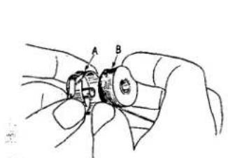
Fig. 8
Place the bobbin in the bobbin case. In one continuous motion with the thumb and forefinger of the right hand draw the bobbin thread through the diagonal slot in bobbin case (A, Fig. 9) under the tension spring and into corner of spring (B). Note the direction of the rotation of the bobbin as the end of the thread is pulled when looking at the bobbin case from the back. The bobbin should rotate counterclockwise.

Fig. 9
REPLACING THE BOBBIN CASE
Have the needle bar at its highest position, allow about two and one half inches of thread to hang free. The bobbin case latch should be opened with the left hand and by reaching under the table and through the opening in the table it should be placed part way into the sewing hook. The latch should then be released and bobbin case snapped into position.
INSERTING THE NEEDLE
Insert the needle in the needle bar as far as it will go, with the spot or scarf toward the right facing the handwheel. Tighten the set screw securely.
The cross hole in needle bar, about 1/4 inch from end (A, Fig. 10) is to show the operator when the needle has been inserted as far up as it will go, and to provide a means for cleaning accumulated lint from needle hole so needle will seat properly.
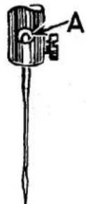
Fig. 10
THREADING THE NEEDLE
Threading diagram (Fig. 3) shows the places where the needle thread passes. Please note that the needle thread passes through the needle eye from left to right.
PREPARATION FOR SEWING
With the left hand hold the end of the needle thread, leaving it slack, and turn the handwheel in operating direction until the needle moves down and up again to its highest position. Pull up the needle thread and the bobbin thread will come up with it through the needle hole in throat plate. Draw both threads under the presser foot.
TENSIONS
A perfect stitch is one in which the needle thread and bobbin thread are locked together in the center of the material being sewed. A stitch of this kind is secured by regulating the tensions on both threads.
BOBBIN THREAD TENSION
The tension on the bobbin case is applied by means of a set screw (A, Fig. 11) which regulates tension spring (B). The tension on the spring is correct when it is just sufficient to hold the case and bobbin, suspended by the bobbin thread.
Remove the bobbin case from the bobbin case holder and turn set screw in spring in a clockwise direction to apply more tensions or counterclockwise to release tension.
When the bobbin thread tension is correct it rarely becomes necessary to make any changes as varying the needle thread tension will usually attain a good stitch.
NEEDLE THREAD TENSION
The needle thread tension is varied by turning the tension regulating nut (G, Fig. 3). Turning the nut in a clockwise direction increases the tension and counterclockwise decreases the tension. This should not be done when the presser foot is in its raised position, and is generally done while the machine is sewing on a piece of scrap material.
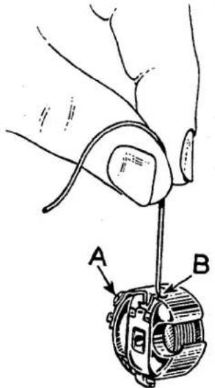
Fig. 11
TO CHANGE THE STITCH LENGTH
Press plunger (H, Fig. 3) in firmly. While holding plunger in, turn handwheel in operating direction until stitch regulating finger is felt to drop into the slot of feed eccentric. Continuing to hold the plunger in, turn handwheel in operating direction to increase the stitch length and in opposite direction to decrease the stitch length.
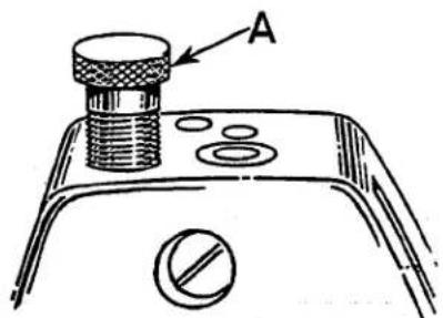
Fig. 12
Comparative stitch lengths are indicated by the graduations on the dial (J) in bed plate, ranging from S (Short) to L (Long). Release the plunger.
PRESSURE ON MATERIAL
The presser spring should exert only enough pressure to make the work feed uniformly. To increase the pressure on the presser foot turn the presser spring regulator (A, Fig. 12) in clockwise direction. Turning the regulator counterclockwise decreases the pressure.
SETTING THE NEEDLE BAR TO HEIGHT
The lower needle bar bushing, the one to which the needle bar is timed, is set at the factory, the distance from the bottom of bushing (B, Fig. 13) to the throat plate seat is 2-9/32 inches.
The four lines engraved on the needle bar are used in setting the bar to height and are referred to as timing lines. The upper two lines are used with the extra short length Type 183 GC or 183 GL needles which are recommended for Styles 61400 A, 61400 E, 61400 F, 61400 G, 61400 H, 61400 N, 61400 P.
The lower two lines are used with the short length Type 180 GL needles which are recommended for Styles 61400 B, 61400 R, 61400 S.
When the needle bar is at its lowest position the upper timing line (A) of the pair selected, dependent on the needle being used, should be even with the lower edge of the lower needle bar bushing (B). To change the position of the needle bar turn the handwheel until the needle bar is at its lowest position, then loosen clamp screw (D) and move the bar to the proper timing line. Keeping the needle bar link at its lowest position, retighten screw securely.
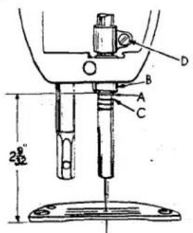
Fig. 13
The illustration (Fig. 13) shows the proper setting of the needle bar on Style 61400 A using extra short needles Types 183GNS or 183GPS. The setting of the needle bar on Style 61400 B using short needles Types 180GNS or 180GPS is accomplished in the same manner except that the lower pair of timing marks on the needle bar is used.
TIMING THE HOOK

Fig. 14
Tip the machine back so that it rests on the rest pin in the table top. Insert a new needle. Loosen the two screws and swing out the bobbin case positioning finger (B, Fig. 14). Loosen the three set screws (A) in the hook and hold the hook and bobbin case holder in such a position as to prevent interference with the needle. Turn the handwheel in operating direction until the needle bar is at its lowest position, continue to turn the handwheel until the needle is ascending and the lowest timing mark of the pair used (C, Fig. 13) in setting the needle bar is even with the lower edge of the needle bar bushing (B).
Turn the hook on the shaft until the point of the hook is even with the center of the needle and as close to the needle as possible without deflecting it. A spacing of .003 to .005 inch between
the needle and the point of the hook is satisfactory. With the hook in this position,
tighten the set screw opposite the hook point securely. Then tighten two remaining screws securely and recheck the timing of hook with the needle at which time the top of the eye of the needle should be about 1/64 inch below the bottom of the hook point. If this condition does not exist, recheck the setting of the needle bar bushing in relation to the throat plate seat.
Adjust the bobbin case holder positioning finger by turning the bobbin case holder until the finger recess is at the top.. Place the projection on the finger into the bobbin case holder recess and tighten the finger attaching screws securely, allowing 1/32 inch clearance between the outside edge of projection and inside edge of bobbin case recess (Fig. 15).
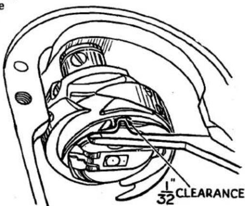
Fig. 15
HOOK LUBRICATION
Insert the bobbin case in the hook and run the machine. CAUTION! Do not run the machine without the bobbin case in the hook, as hook damage may result. After a minute of running, place a piece of white paper directly below the hook, continue running the machine, check the delivery of oil from the hook. The hook is properly lubricated when a definite pattern of oil appears on the test paper after a five second run.
Running through the middle of the hook shaft is an oil metering insert pin which controls the flow of oil to the hook. An occasional cleaning of this insert pin will insure its proper operation.
To withdraw the pin from the hook shaft, the hook must first be removed. The end of the insert pin has an internal thread into which Union Special metering pin extractor No. 21227 AZ may be screwed and the pin withdrawn.
The metering insert pin should fit snugly in the hook shaft. If it is loose it should be withdrawn and kinked slightly.
When re-assembling the hook it must be re-timed as previously instructed.
HOOK SHAFT
Should it become necessary to replace the hook shaft, drain the oil from the gear case and remove gear case cover and hook. Loosen gear set screws (A, Fig. 16) and carefully withdraw hook shaft. Remove thrust collar from left end of hook shaft by loosening screws (B). To re-assemble, slide collar onto the hook shaft with faced end adjacent to bushing (C) and insert hook shaft as far as it will go. Tighten set screws (A) making sure that one of the set screws bears against the flat on the shaft. Check for bind. Then set the thrust collar against bushing (C), tighten screws (B) and check for bind.
If, when the hook shaft is removed, the gear (D), the thrust washers (E) and the oil seal washer (F) should drop into the gear case they will have to be re-assembled as shown in the sketch. Clean, dry, and re-seal gasket and housing cover using gasket cement. Fill gear case with proper oil.
Re-time the hook as previously described.
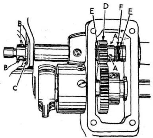
Fig. 16

Fig. 17
FEED DOG HEIGHT
In regulating the height of the feed dog, it should be at its highest position and the presser foot resting directly against it.
The feed dog holder attaching screw (A, Fig. 17) should be loosened slightly, and regulating screw (B) should be turned either clockwise to raise the feed dog or counterclockwise to lower it. Make sure that the bottom of the shank of the feed dog holder rests against the head of regulating screw.
A suggested initial setting is as follows: Feed dogs having 22 or more teeth per inch should show about 3/64 inch above the throat plate at highest point of travel, those having 16 or less teeth per inch should show the depth of a full tooth above the throat plate. The feed dog can be tilted up or down as required by loosening screws (A and C).
Loosen feed dog holding screws (D) to space the feed dog, front to back or sideways in throat plate.
PRESSER BAR CONNECTION

Fig. 18
The presser bar connection (A, Fig. 19) should be set so that it bears against the hand lifter (B) at all times.
This is accomplished by turning the machine over on its side, loosening lock nut (G, Fig. 18) and relocating the stop screw (E) on the lifter lever bell crank (F). By turning the stop screw counterclockwise, the presser bar connection is brought closer to the hand lifter. While turning the screw, move the hand lifter up and down continuously until no free motion can be felt. Tighten lock nut (G) to lock screw in position.
PRESSER BAR GUIDE
When locating the presser bar guide (C) Fig. 19) the presser foot must rest directly against the throat plate with the feed dog in its lowest position.
The guide is properly set when there is a 1/16 inch space between presser bar guide and the connection.
To obtain this setting, loosen set screw (D) in the guide and insert screw driver between the connection and the guide. Tap on presser foot to insure its being down on the throat plate, center the foot by turning it so that needle enters the middle of its slot and re-tighten screw (D) in guide.
THREAD CONTROL
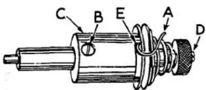
Fig. 20

Fig. 19
Test check spring tension (A, Fig. 20). There should be enough tension to insure a good returning snap when spring is depressed and released. Should it require adjusting, loosen set screw in the head on right side of tension post (G, Fig. 21) and remove tension post assembly. Partially loosen tension post set screw (B, Fig. 20) in tension post socket (C). Holding the socket in the left hand turn the tension post (D) counterclockwise with the right hand until the check spring moves away from the upper stop (E) and has no tension on it. Turn the tension post (D) in a clockwise direction until the spring again touches the upper stop (E). Then proceed further in the same direction until the desired tension is obtained. When correct-
ly set, the tension post set screw (B) should be drawn up snugly but not forcefully. Further adjustment of the check spring tension can be made by inserting a screw driver into the slotted end of the tension post (D) and turning in the required direction.
Replace tension assembly with the check spring about 1/2 inch above the thread take-up wire. While the tension post assembly is being replaced, the presser foot should be resting on the throat plate.
The frame take-up eyelet (A, Fig. 22) should be set at its lowest position.
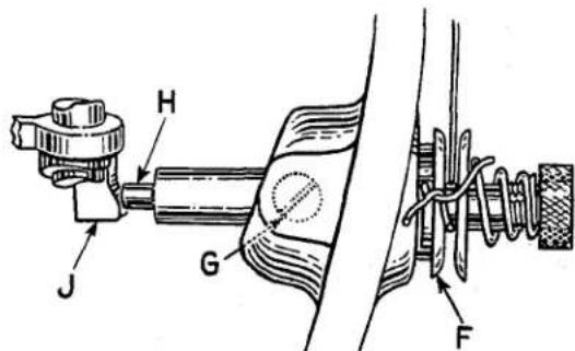
Fig. 21
For the final setting of check spring, sew slowly on a piece of material and observe the action of the check spring. The thread from the check spring to the take-up thread wire should be taut when the take-up is at the bottom of its stroke.
LOCATING TENSION RELEASE MECHANISM

Fig. 22
The tension assembly should be located in bed from front to back, so that when the presser foot is raised to its highest position, the tension discs (F, Fig. 21) are opened just enough to allow the thread to pass through the discs freely.
To position the tension assembly, see that set screw in bed (G, Fig. 21) is loose and tension assembly adjusting screw (B, Fig. 22) is screwed down to the bed.
Lift the presser foot hand lifter to its highest position; with the left hand grasp the thread and pull it through the tensions, with the right hand push tension post deeper into the machine until release pin (H, Fig. 21) pressing against the presser bar connection (J) has opened the tension discs just enough to allow the thread to pull through freely. Re-tighten set screw (G), turn tension assembly adjusting screw (B, Fig. 22) counterclockwise until it contacts the flange of the tension post socket.
NOTE: When tacking is required, the tension assembly should be adjusted so that the pressure foot may be raised to clear the heaviest seam without releasing the needle thread tension.
STITCH REGULATING PLUNGER LOCK
To lock the stitch regulating plunger at any desired stitch length tilt the machine back against rest pin and tighten screw (F, Fig. 24) securely.
FEED TIMING
The definite relationship which exists between the feed dog and the needle bar motions is referred to as timing.
To check for the proper setting of the feed timing, proceed as follows:
- Set the stitch length midway between long and short as described in "To Change The Stitch Length."
- Check to see that the feed dog is set at its proper height as described in "Feed Dog Height" (Fig. 17).
- Turn the handwheel in the operating direction until the top of the needle eye is even with the top surface of the throat plate.
- For Styles 61400 A, 61400 E, 61400 F, 61400 G, 61400 H, 61400 N, 61400 P, top of the feed dog teeth should be level with the upper surface of throat plate.
4A. For Styles 61400 B, 61400 R, 61400 S, top of the feed dog teeth should be about .010 inch above the upper surface of the throat plate. An advanced or fast timing is one in which the top of the feed dog teeth have sunk below the surface of the throat plate, before the top of the descending needle eye has reached the surface of the throat plate. Conversely, a retarded or slow feed timing is one in which the top of the feed dog teeth are still above the surface of the throat plate when the top of the descending needle eye has reached the surface of the throat plate. A simple method of advancing or retarding the feed timing slightly to meet the varying conditions in material and operations is provided in the head of the machine.
CAUTION! A change in the feed timing always requires an additional change in the setting of the sewing hook.
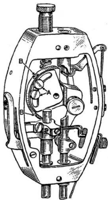
Fig. 23
FEED TIMING (Continued)
To change the setting of the feed timing proceed as follows:
- Remove needle as a safety precaution.
- Loosen the two screws (A, Fig. 23) holding the counterweight to the segment plate, and the two screws (B) holding the counterweight to main shaft.
- Hold handwheel and turn the counterweight in a clockwise direction to retard the feed and a counterclockwise direction to advance the feed. The two screws (A) holding the counterweight to the segment plate will be moved toward either end of segment plate slot, depending on whether the feed timing was advanced or retarded.
- Re-tighten all screws securely. It is very important that the counterweight should not be allowed to slip.
MACHINE TIMING
If at any time the feed driving gears should have to be removed, the machine will have to be re-timed by the following procedure:

Fig. 24
- Lay machine on its side on the bench.
- Remove the large gear housing cover. Note caution should be observed that machine is tilted far enough back so oil will not leak out. Also be careful in removing the housing cover that the gasket is not mutilated.
- Loosen screws (B, Fig. 24) and slide gear (A) to the extreme right so it is out of mesh with the idler gear (D).
- Looking through the stitch length indicator window on the top of the bed plate, rotate the lower main shaft (C) in the operating direction until the timing mark "-0-" appears between the pointers of the indicator window. Then rotate upper main shaft in the operating direction until the needle bar reaches its highest position. Carefully turn gear (A), without disturbing the lower main shaft setting, until the set screw lies directly above the flat in the lower main shaft. The gears should then be engaged as closely as possible in this position. While holding the gear and thrust collar (E) tightly between thumb and forefinger tighten set screw against flat in shaft securely, then tighten the second set screw and check to see that there is no end play in the shaft and that the machine revolves freely.
- Clean, dry and re-seal gasket and housing cover using gasket cement.
- Replace housing cover. Check position of oil distributing plate as previously described under "Lubrication."
- Re-set sewing hook.
MECHANIC'S INSTRUCTIONS
FOR
TOP ROLLER FEED MACHINES
STYLES 61400 N, 61400 P, 61400 R, 61400 S
All adjustments for the top roller feed machines are the same as for the plain feed Lockstitch machines, except for the timing and setting of the top roller feed.
CAUTION! At no time should the machine be run or turned over by hand with the two feeds in direct contact with one another as chipped teeth may result.
Synchronization of the top roller feed with the lower feed is of the utmost importance. The top roller should begin feeding at the same time that the feed dog begins its feeding cycle and should continue feeding until the feed dog has completed its feeding cycle.
The top roller feed has been synchronized with the lower feed at the factory. However, if at any time, any parts of the mechanism involved have to be replaced, observing the following steps will simplify the synchronization and setting of the top roller feed:
- The top feed roller on Styles 61400 N and 61400 R, which are equipped with the roller to the right of the needle bar, should be set as close to the presser foot as possible without contacting. Loosen screw (A, Fig. 25) which holds the shank of the roller. Lift the presser foot off the throat plate by means of the hand lifter and move the top roller. Re-tighten screw. On Styles 61400 P and 61400 S, which have the feed roller behind the needle bar, set the roller so that its slot is directly in line with the needle.

natural_image
Technical line drawing of a sewing machine needle and tool (no text or symbols)Fig. 25
-
Set the stitch length of the main feed as previously described at its longest travel so that the letter "L" is visible in the indicator window in bed plate.
-
Lay the machine on its side and set the stitch length of the top roller feed at its longest travel so that the pointer (A, Fig. 26) is at the letter "L" on the indicator (B). To accomplish this, depress the lever (C) and while holding it down, turn the handwheel in operating direction until the point of the lever is felt to drop into the slot (D) in the adjustable eccentric. Still holding the lever down, continue turning the handwheel until it can be turned no further. If at this point, the pointer (A) is not as the letter "L", loosen the two screws (E) in the hub of the indicator and turn the indicator on the shaft so that the letter "L" is at the pointer. Tighten screws.
-
Now check the synchronization of the top feed roller and the main feed. Raise the top roller off the bed plate by means of the hand lifter lever, turn handwheel in operating direction and observe the top roller and main feed dog. They should begin feeding at the same time. To synchronize the two feeds, lay the machine on its side and loosen the time screw (F, Fig. 26) in the adjustable eccentric. The time screw can be easily identified by the words "time spot" stamped on the right side of the eccentric. Now loosen set screw (G). If the top feed roller began feeding before the main feed dog, turn the eccentric (H) in the opposite direction from the operating direction of the main shaft. The operating direction of the main shaft is indicated by arrow (Fig. 26). Only a slight movement of the eccentric is necessary to change the time at which the top roller commences to feed. Tighten the two screws (F and G) and check synchronization. When tightening the two screws do not force the eccentric against the clutch driving arm as a bind may be created. If the main feed dog began feeding before the top feed roller, proceed as above except turn the eccentric in the same direction as the operating direction of the main shaft.
-
Changing the position of the top feed eccentric on the shaft will affect the location of the top feed stitch length indicator (B, Fig. 26) and it will now have to be re-set so that pointer stops at the letter "L" as described in paragraph 3 above.
MECHANIC'S INSTRUCTIONS
FOR
TOP ROLLER FEED MACHINES
STYLES 61400 N, 61400 P, 61400 R, 61400 S
(Continued)
- Set the main feed to produce the required length of stitch in the same manner as previously
described. When checking the length of stitch produced by the main feed place a screw driver
or similar object under the top feed shaft and raise the feed roller (Fig. 25) so that the actual stitch length of the main feed can be observed.
7.
Now set the stitch length of the top roller feed so that with two plies of material under the presser foot, both plies feed uniformly and straight and that neither ply feeds faster than the other. The top roller feed stitch length is set in the same manner as described in paragraph 3, except that in shortening the stitch, the handwheel is turned opposite to the operating direction. The letters on the graduations of the main feed and top roller feed stitch length indicators have no relationship to one another, so that with both indicators set at the same letters, the stitch lengths of both feeds will not necessarily be the same.
Fig. 26
USEFUL SUGGESTIONS
If the machine fails to work satisfactorily, though apparently in good repair, it is possible that some minor trouble exists. For this reason delay may be avoided by acting on the following:
- See that the needle is set properly; that it is the recommended needle; that it is straight and free from nicks and rough places; that it is inserted in the needle bar as far up as it will go; and that there is clearance all around needle as it enters the throat plate.
- See that the machine is threaded correctly and the needle thread is delivered to the machine properly.
- See that the proper tension is applied to the threads.
- See that the presser foot is set so that the needle does not strike it.
- See that the feed dog is not striking the hook or throat plate.
- Take off throat plate and remove accumulated lint from feed dog slots and hook.
- See that there are no nicks or cuts in the wall of the throat plate needle hole. String out this hole with fine emery cord or cloth.
- See that the take-up spring acts freely, is not grooved or nicked. Remove any gummy oil and dirt around tension discs.
- See that the hook thread deflector is free from nicks and burrs.
- See that the point of the hook is not blunted, broken or nicked.
- See that the hook is timed correctly.
- See that the feed is timed correctly.
- See that bobbin case holder finger is set 1/32 inch from bobbin case holder, which is the correct position for passing the thread.
- See that all screws are tight.
ORDERING REPAIR PARTS
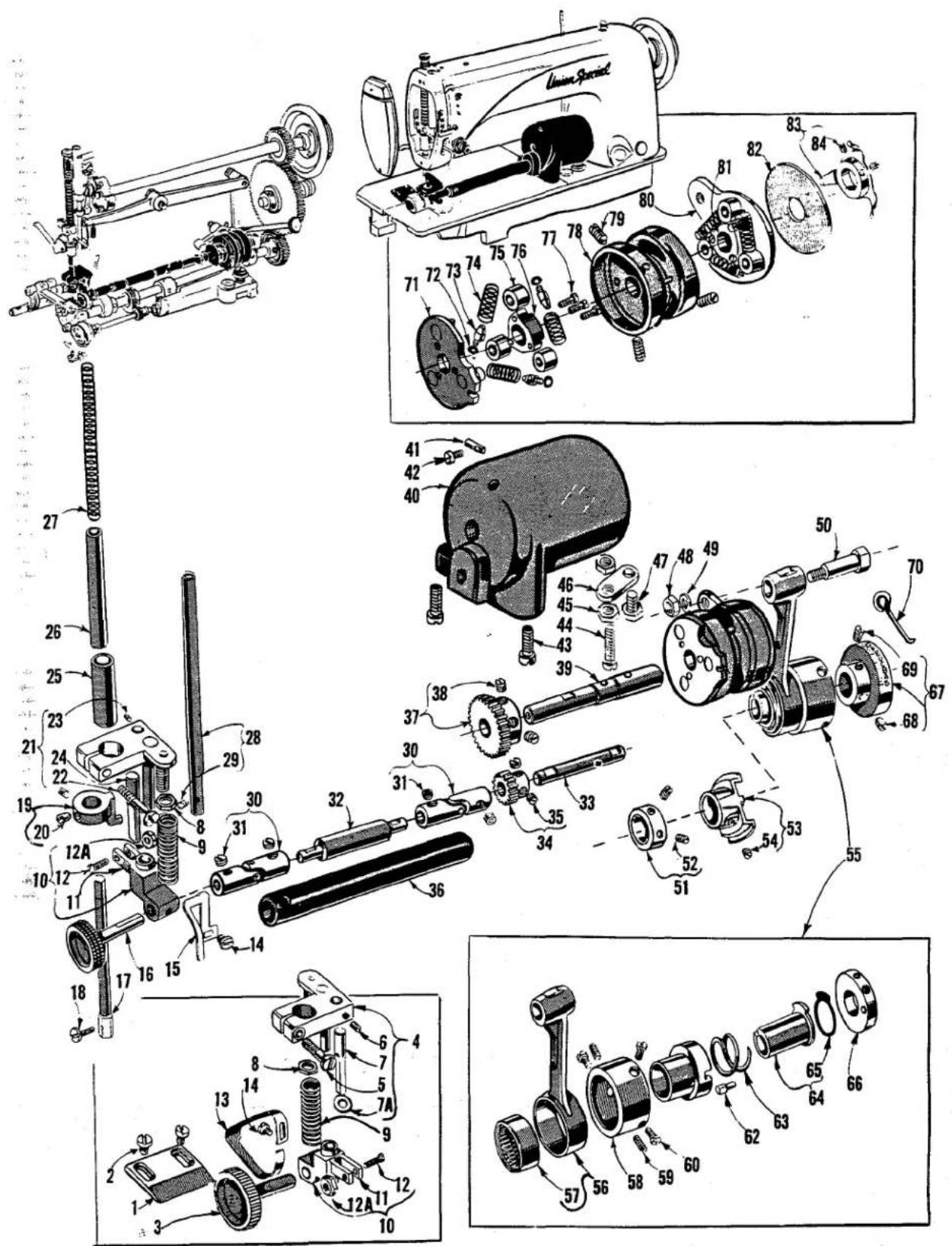
ILLUSTRATIONS
This catalog has been so arranged as to simplify the ordering of repair parts. Exploded views of the various sections of the mechanism are shown so that the parts may be seen in their actual position in the machine. On the page opposite the illustration will be found the listing of the parts with their part number, description and the number of pieces required in the particular view being shown.
The numbers in the first column are reference numbers only and indicate the position of the part in the illustration. The reference number should never be used in ordering parts. Always use the part number shown in the second column.
Those component parts of sub-assemblies which can be furnished for repairs are indicated by the fact that their descriptions are indented under the descriptions of the main sub-assembly. Example:
| 12 | 61434 | Feed Bar | 1 |
| 13 | 89 | Screw | 1 |
| 14 | 88 D | Screw | 1 |
| 15 | 61439 A | Feed Dog Holder Support | 1 |
In those cases where the parts for the various styles in Class 61400 are not the same the difference will be shown in the illustrations and descriptions. When a part is used in all machines covered by this catalog no machine style will be mentioned.
Following the pages of exploded views will be found several pages of illustrations of throat plates, feed dogs, presser feet, attachments, and miscellaneous parts. Since it would be impossible to show all these parts in the exploded views, they have been arranged so that the throat plates and feed dogs that can be used together are grouped on the pages of illustrations, and presser feet and attachments have been arranged, as closely as possible, according to similarity in design and use. On the descriptive pages covering these parts, no reference numbers or number of pieces required are given.
At the back of the book will be found a numerical index of all the parts shown in this book, which will facilitate locating the illustration when only the part number is known.
IDENTIFYING PARTS
Where the construction permits, each part is stamped with its part number. Some of the smaller parts are stamped with an identification letter to distinguish them from parts similar in appearance.
All part numbers represent the same part, regardless of the catalog in which they appear.
USE GENUINE NEEDLES AND REPAIR PARTS
Success in the operation of these machines can be secured only with genuine Union Special Needles and Repair Parts as furnished by the Union Special Machine Company, its subsidiaries and authorized distributors. They are designed according to the most approved scientific principles, and are made with utmost precision. Maximum efficiency and durability are assured.
Genuine needles are packaged with labels marked Union Special. Genuine repair parts are stamped with the Union Special trademark. Each trademark is your guarantee of the highest quality in materials and workmanship.
TERMS
Prices are strictly net cash and subject to change without notice. All shipments are forwarded f. o. b. shipping point. Parcel Post shipments are insured unless otherwise directed. A charge is made to cover the postage and insurance.
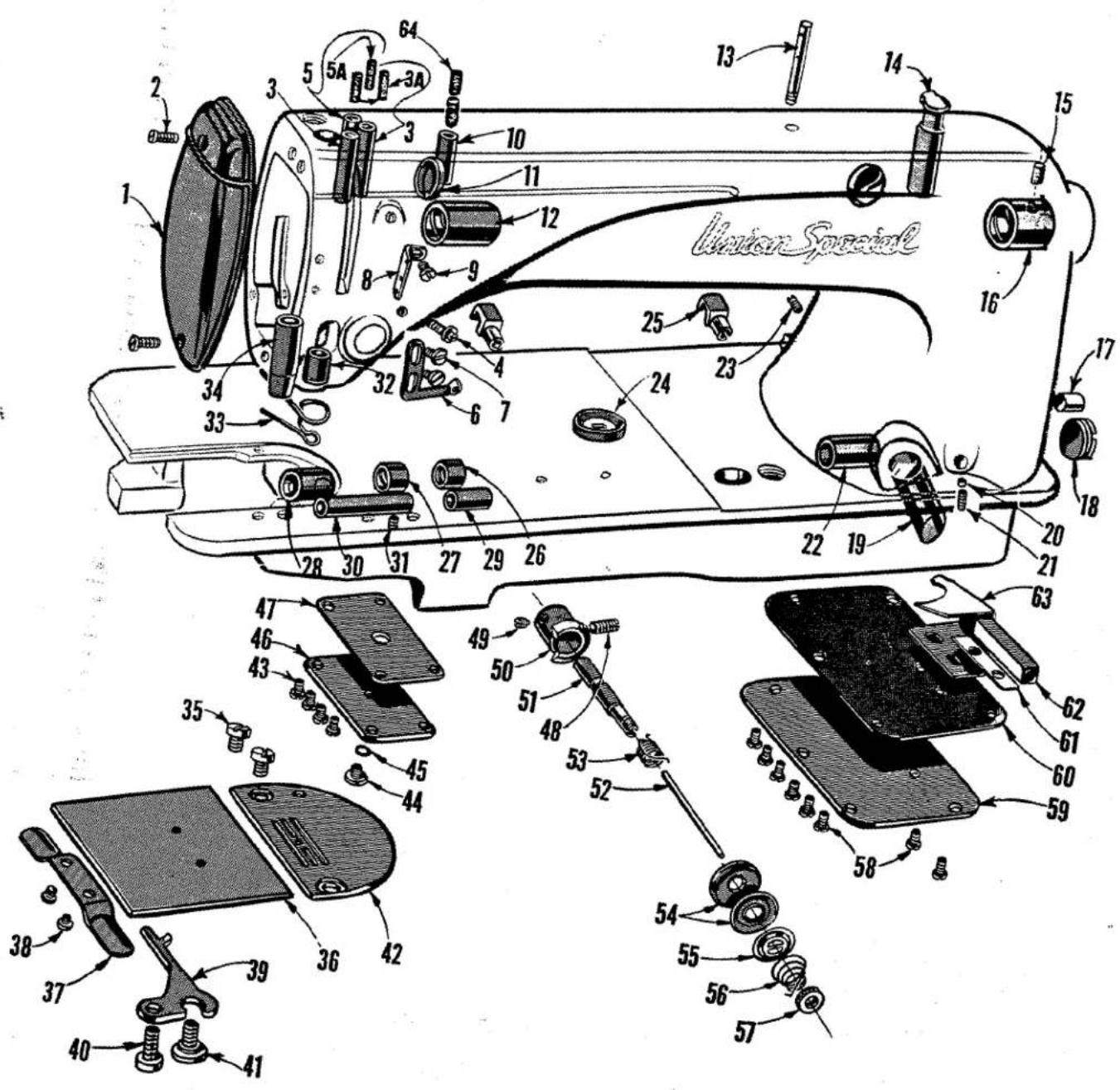
MAIN FRAME, MISCELLANEOUS BUSHINGS, COVERS AND PLATES
| Ref. No. | Part No. | Description | Amt. Req. |
| 1 | B61382 H | Head Cover | 1 |
| 2 | 22569 B | Screw | 2 |
| 3 | 61293 | Oil Tube | 2 |
| 3A | 666-126 | Oil Wick, for No. 61293 | 2 |
| 4 | 22863 B | Tension Assembly Adjusting Screw | 1 |
| 5 | 61393 C | Oil Tube, for all Styles except 61400 N, P | 1 |
| 61393 E | Oil Tube, for Styles 61400 N, P | 1 | |
| 5A | 666-127 | Oil Wick, for No. 61393 C | 1 |
| 6 | 61351 J | Thread Eyelet | 1 |
| 7 | 22585 A | Screw | 2 |
| 8 | 61271 | Thread Eyelet | 1 |
| 9 | 22570 A | Screw | 1 |
| 10 | 61393 B | Oil Tube | 1 |
| 11 | 61293 N | Plug, for inside of arm | 2 |
| 12 | 61490 A | Main Shaft Bushing, left | 1 |
| 13 | 61272 | Needle Thread Guide Pin | 1 |
| 14 | 61394 AE | Oil Cup | 1 |
| 15 | 666-104 | Oil Wick | 1 |
| 16 | 61490 | Main Shaft Bushing, right | 1 |
| 17 | 50-558 Blk. | Plug | 1 |
| 18 | 22539 D | Plug Screw | 1 |
| 19 | 50-568 Blk. | Oil Sight Gauge | 1 |
| 20 | 61245 G | Stitch Regulator Thumb Screw Locking Insert | 1 |
| 21 | 22597 A | Screw | 1 |
| 22 | 61432 B | Feed Driving Shaft Bushing, right | 1 |
| 23 | 22597 A | Screw | 1 |
| 24 | 61449 H | Stitch Regulator Indicator Window | 1 |
| 25 | 61375 | Hinge Stud | 2 |
| 26 | 61432 D | Feed Driving Shaft Oil Retaining Bushing, right | 1 |
| 27 | 61432 E | Feed Driving Shaft Oil Retaining Bushing, left | 1 |
| 28 | 61432 C | Feed Driving Shaft Bushing, left | 1 |
| 29 | 61341 D | Hook Shaft Bushing, right | 1 |
| 30 | 61341 C | Hook Shaft Bushing, left | 1 |
| 31 | 96 A | Screw | 1 |
| 32 | 61454 | Needle Bar Bushing, lower | 1 |
| 33 | 61470 | Needle Thread Guide, for Styles 61400 A, B, E, F, G, H, J, AA, BA | 1 |
| 61470 B | Frame Thread Guide, for Styles 61400 N, P, R, S | 1 | |
| 34 | 61457 C | Presser Bar Bushing, lower, for Styles 61400 A, B, E, F, G, H, J, AA, BA | 1 |
| 35 | 376 | Screw | 2 |
| 36 | 61202 | Bed Slide | 1 |
| 37 | 61273 | Bed Slide Spring | 1 |
| 38 | 91 A | Screw | 2 |
| 39 | 61414 A | Bobbin Case Holder Positioning Finger | 1 |
| 40 | 93 | Screw | 1 |
| 41 | 22742 | Screw | 1 |
| 42 | Throat Plate, see pages of Throat Plates and Feed Dogs | 1 | |
| 43 | 22570 A | Screw | 4 |
| 44 | 22730 | Plug Screw | 1 |
| 45 | 660-257 | Gasket | 1 |
| 46 | 61282 A | Cover, for hook shaft gear case | 1 |
| 47 | 61282 E | Gasket | 1 |
| 48 | 22597 E | Set Screw | 1 |
| 49 | 89 | Set Screw | 1 |
| 50 | 61492 A | Tension Post Socket | 1 |
| 51 | 61492 | Tension Post | 1 |
| 52 | 61292 G | Tension Release Pin | 1 |
| 53 | 61453 | Take-up Spring | 1 |
| 54 | 109 | Tension Disc | 2 |
| 55 | 61292 H | Tension Release Washer | 1 |
| 56 | 61392 F-9 | Tension Spring, for Styles 61400 A, E, F, G, H, J, N, P, AA | 1 |
| 61392 F-14 | Tension Spring, for Styles 61400 B, R, S, BA | 1 | |
| 57 | 61292 C | Tension Nut | 1 |
| 58 | 22570 A | Screw | 8 |
| 59 | 61382 J | Cover, for feed driving shaft gear case | 1 |
| 60 | 61282 D | Gasket | 1 |
| 61 | 61394 R | Gasket | 1 |
| 62 | 61394 Q | Oil Distributing Plate Retaining Block | 1 |
| 63 | 61394 P | Oil Distributing Plate | 1 |
| 64 | 666-20 | Oil Wick | 2 |
| Ref.No. | PartNo. | Description | Amt.Req. |
| 1 | Presser Foot, see pages of Presser Feet | 1 | |
| 2 | 22775 | Screw | 1 |
| 3 | 61457 | Presser Bar, for Styles 61400 A, B, E, F, G, H, J, AA, BA | 1 |
| 4 | 61453 B | Take-up Spring Thread Wire | 1 |
| 5 | 61459 B | Presser Bar Guide, for Styles 61400 N, P, R, S | 1 |
| 61459 A | Presser Bar Guide, for Styles 61400 A, B, E, F, G, H, J, AA, BA | 1 | |
| 6 | 77 | Screw | 1 |
| 7 | 22596 D | Screw, for No. 61459 B | 1 |
| 93 A | Screw, for No. 61459 A | 1 | |
| 8 | 61256 | Presser Spring, for Styles 61400 A, E, F, G, H, J, N, P, R, S, AA | 1 |
| 61356 | Presser Spring, for Styles 61400 B, BA | 1 | |
| 9 | 61256 G | Washer | 1 |
| 10 | 61457 B | Presser Spring Regulator | 1 |
| 13 | 61417 | Needle Bar, for Styles 61400 A, B, E, F, G, H, J, AA, BA | 1 |
| 14 | 22768 A | Needle Set Screw | 1 |
| 15 | 61255 | Needle Bar Connection | 1 |
| 16 | 22562 B | Screw | 1 |
| 17 | 96 | Screw | 1 |
| 18 | 61454 D | Needle Bar Bushing, upper, for all Styles except 61400 N, P | 1 |
| 18A | 61454 A | Needle Bar Bushing, upper, for Styles 61400 N, P | 1 |
| 18B | 61454 B | Spring Clip, for Styles 61400 N, P | 1 |
| 18C | 666-186 | Oil Felt, for Styles 61400 N, P | 1 |
| 18D | CL21 | Oil Wick, for 61393 E, Styles 61400 N, P | 1 |
| 19 | 29486 B | Take-up Lever and Needle Bar Link Assembly | 1 |
| 20 | 22757 C | Screw | 1 |
| 21 | 61255 H | Needle Bar Link | 1 |
| 22 | 61351 K-625 | Needle Bearings, .0625 inch diameter | 38 |
| 61351 K-626 | Needle Bearings, .0626 inch diameter | 38 | |
| 61351 K-627 | Needle Bearings, .0627 inch diameter | 38 | |
| 23 | 61252 J | Crank Pin | 1 |
| 24 | 61351 C | Thrust Washer | 1 |
| 25 | 61351 Q | Take-up Lever Assembly | 1 |
| 26 | 22597 A | Screw | 1 |
| 27 | 61251 D | Take-up Lever Pin | 1 |
| 28 | 660-205 | Retaining Ring | 1 |
| 29 | 61451 C | Thrust Washer, for take-up lever | if required |
| 30 | 61391 C | Main Shaft Counterweight, for Styles 61400 A, E, F, G, H, J, N, P, AA | 1 |
| 61391 D | Main Shaft Counterweight, for Styles 61400 B, R, S, BA | 1 | |
| 31 | 22894 V | Screw | 2 |
| 31A | 22880 | Spot Screw | 1 |
| 31B | 22570 B | Set Screw | 1 |
| 32 | 22596 D | Screw | 2 |
| 33 | 8372 A | Washer | 2 |
| 34 | 61322 B | Main Shaft | 1 |
| 35 | 61360 | Main Shaft Driving Gear | 1 |
| 36 | 22884 | Screw | 2 |
| 37 | 61421 | Handwheel Assembly, for No. 1 "V" or Round Belt | 1 |
| 38 | 22574 | Screw | 3 |
| 39 | 61321 L | Hub Washer | 1 |
| 40 | 61321 J | Handwheel | 1 |
| 41 | 61421 A | Pulley Hub | 1 |
| 42 | 22894 AB | Screw | 2 |
| 43 | 61458 | Presser Bar Connection, for Styles 61400 A, B, E, F, G, H, J, AA, BA | 1 |
| 61458 A | Presser Bar Connection, for Styles 61400 N, P, R, S | 1 | |
| 44 | 22892 | Screw | 1 |
| 45 | 22560 B | Screw, for No. 61458 A on Styles 61400 N, P, R, S | 2 |
| 46 | 61265 | Hand Lifter | 1 |
| 47 | 22799 M | Screw Pin | 1 |
| 48 | 61267 | Lifter Lever Link | 1 |
| 49 | 61466 A | Lifter Lever | 1 |
| 50 | 22890 | Screw, left thread | 1 |
| 51 | 61368 A | Lifter Lever Extension Stud and Connecting Rod, complete | 1 |
| 52 | 61368 | Lifter Lever Connecting Rod | 1 |
| 53 | 61366 C | Lifter Lever Extension Stud | 1 |
| 54 | 652 B-20 | Lock Washer | 1 |
| 55 | 9937 | Nut | 1 |
| 56 | 660-142 | Cotter Pin | 1 |
| 57 | 61468 | Lifter Lever Bell Crank, for Styles 61400 A, B, E, F, G, H, J, AA, BA | 1 |
| 61368 E | Lifter Lever Bell Crank, for Styles 61400 N, P, R, S | 1 | |
| 58 | 22817 A | Stud | 1 |
| 59 | 22874 F | Screw | 1 |
| 60 | 22712 F | Screw | 1 |
| 61 | 61368 F | Roller | 1 |
| 62 | 22758 B | Screw | 1 |
| 63 | 15872 F | Spring | 1 |
| 64 | 61267 G | Spring Pin | 1 |

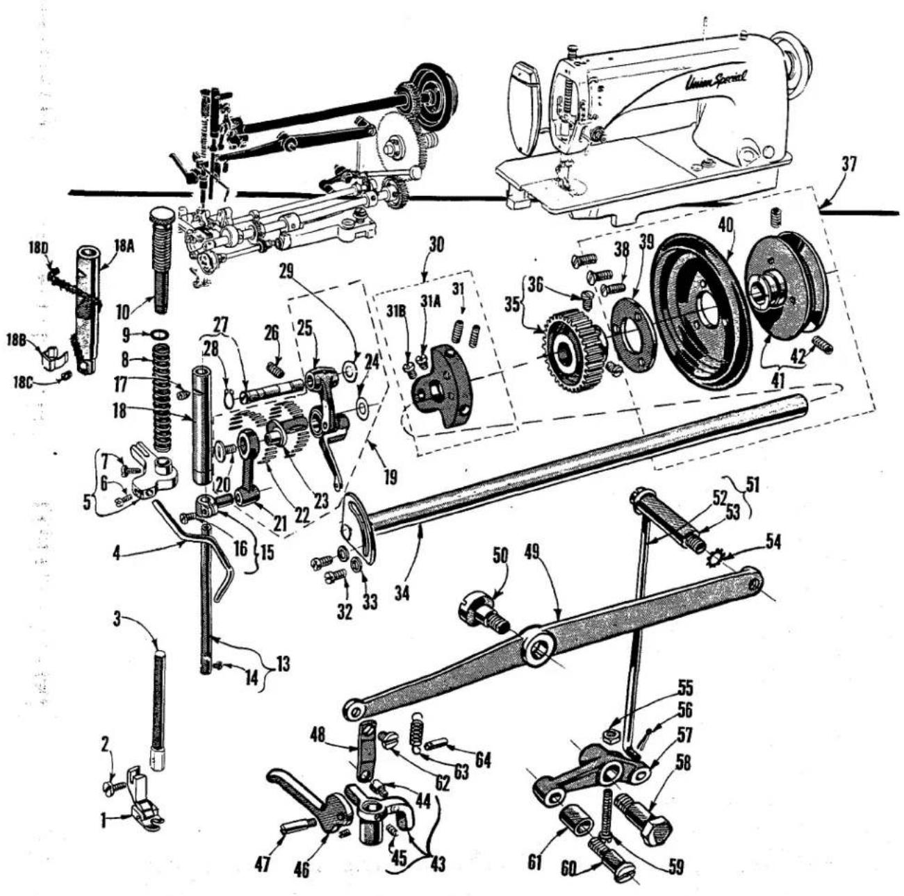
FEED DRIVING AND STITCH REGULATING MECHANISM
| Ref. No. | Part No. | Description | Amt. Req. |
| 1 | 61236 | Feed Rocker---- | 1 |
| 2 | 61336 U | Bushing---- | 2 |
| 3 | 22894 E | Screw---- | 2 |
| 4 | 61235 | Feed Bar and Feed Rocker Connection Link Shaft---- | 2 |
| 5 | 90 | Screw---- | 2 |
| 6 | 61336 Y | Feed Rocker Oil Wick---- | 1 |
| 7 | 61236 G | Feed Rocker Shaft---- | 1 |
| 8 | 22528 | Screw---- | 1 |
| 9 | 61439 | Feed Dog Holder---- | 1 |
| 10 | Feed Dog, see pages of Feed Dogs and Throat Plates---- | 1 | |
| 11 | 22768 | Screw---- | 2 |
| 12 | 61434 | Feed Bar---- | 1 |
| 13 | 89 | Screw---- | 1 |
| 14 | 88 D | Screw---- | 1 |
| 15 | 61439 A | Feed Dog Holder Support---- | 1 |
| 16 | 61233 N | Feed Link---- | 1 |
| 17 | 22845 D | Feed Lift Link Stud---- | 1 |
| 18 | 61434 G | Washer---- | 1 |
| 19 | 15037 A | Nut---- | 1 |
| 20 | 22775 A | Screw---- | 1 |
| 21 | 29126 BS | Feed Drive Eccentric Assembly---- | 1 |
| 22 | 61438 A | Connection Rod---- | 1 |
| 23 | 88 | Screw---- | 1 |
| 24 | 660-225 | Needle Bearing---- | 1 |
| 25 | 61437 C | Feed Driving Eccentric Retaining Housing---- | 1 |
| 26 | 719 | Screw---- | 1 |
| 27 | 22564 B | Screw---- | 3 |
| 28 | 61449 B | Stitch Regulating Thrust Spring---- | 1 |
| 29 | 61449 | Stitch Regulating Eccentric---- | 1 |
| 30 | 61449 A | Stitch Regulating Eccentric Friction Disc---- | 1 |
| 31 | 61437 B | Feed Driving Eccentric Pivot Pin---- | 1 |
| 32 | 61437 A | Feed Driving Eccentric Timing Collar---- | 1 |
| 33 | 22764 B | Time Spot Screw---- | 1 |
| 34 | 22802 A | Screw---- | 1 |
| 35 | 51242 M | Washer---- | 1 |
| 36 | 61449 F | Stitch Regulating Pawl---- | 1 |
| 37 | 61449 E | Stitch Regulating Pawl Collar---- | 1 |
| 38 | 22880 | Screw---- | 1 |
| 39 | 22845 G | Screw---- | 1 |
| 40 | 61248 H | Stitch Regulating Shaft Collar---- | 2 |
| 41 | 531 | Screw---- | 2 |
| 42 | 61443 | Hook Shaft Driving Gear---- | 1 |
| 43 | 22894 J | Set Screw---- | 2 |
| 44 | 61449 G | Stitch Length Indicator---- | 1 |
| 45 | 95 | Set Screw---- | 1 |
| 46 | 96 | Time Spot Screw---- | 1 |
| 47 | 22743 | Plug Screw---- | 1 |
| 48 | 61432 A | Feed Driving Shaft---- | 1 |
| 49 | 50-552 Blk. | Plug---- | 1 |
| 50 | 61360 G | Feed Driving Shaft Collar---- | 1 |
| 51 | 22884 | Screw---- | 2 |
| 52 | 61260 A | Feed Driving Shaft Gear---- | 1 |
| 53 | 22884 | Screw---- | 2 |
| 54 | 61348 A | Stitch Regulator Shaft---- | 1 |
| 55 | 61447 | Stitch Regulator Plunger Spring---- | 1 |
| 56 | 93 A | Screw---- | 1 |
| 57 | 61246 A | Stitch Regulator Plunger Lever---- | 1 |
| 58 | 161 | Collar---- | 1 |
| 59 | 88 | Screw---- | 1 |
| 60 | 61445 | Stitch Regulator Plunger---- | 1 |
| 61 | 61264 A | Intermediate Gear Shaft Collar, left---- | 1 |
| 62 | HA61 D | Screw---- | 2 |
| 63 | 61261 A | Feed Driving Intermediate Gear---- | 1 |
| 64 | 61263 | Bushing---- | 1 |
| 65 | 61264 | Intermediate Gear Shaft Collar, right---- | 1 |
| 66 | HA61 D | Screw---- | 2 |
| 67 | 62262 | Intermediate Gear Shaft---- | 1 |
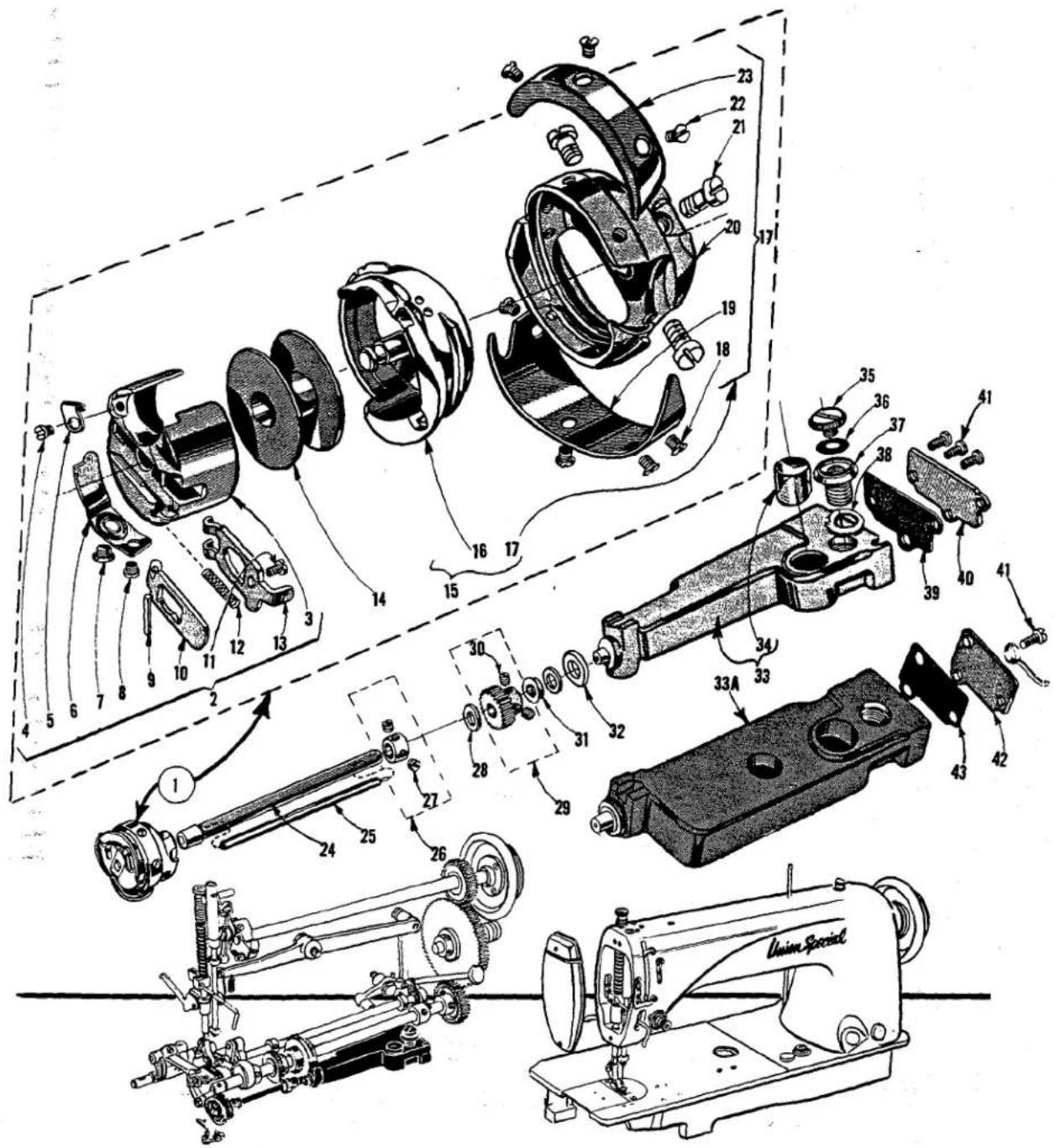
ROTARY HOOK AND LUBRICATING MECHANISM
| Ref.No. | PartNo. | Description | Amt.Req. |
| 1 | 29474 G | Rotating Hook Assembly, for 30-3 and smaller thread | 1 |
| L628 | Rotating Hook Assembly, for sizes 16-4 to 30-4 thread | 1 | |
| 2 | 61413 E | Bobbin Case Assembly | 1 |
| 3 | 61413 F | Bobbin Case | 1 |
| 4 | 22564 F | Screw | 1 |
| 5 | 61413 G | Eyelet | 1 |
| 6 | 61414 C | Bobbin Case Tension Spring | 1 |
| 7 | 22716 B | Tension Regulating Screw | 1 |
| 8 | 22564 E | Screw | 1 |
| 9 | 61216 | Bobbin Case Latch Hinge Pin | 1 |
| 10 | 61415 A | Bobbin Case Latch Lever | 1 |
| 11 | 22564 E | Stop Screw | 1 |
| 12 | 61216 N | Bobbin Case Latch Spring | 1 |
| 13 | 61415 | Bobbin Case Latch | 1 |
| 14 | 61212 | Bobbin | 1 |
| 15 | 61407 B | Hook, Thread Retainer, Thread Deflector and Bobbin Case Holder Assembly, for 30-3 and smaller thread | 1 |
| 16 | 61414 | Bobbin Case Holder, for 30-3 and smaller thread | 1 |
| L629 | Bobbin Case Holder, for sizes 16-4 to 30-4 thread | 1 | |
| 17 | 61407 C | Hook, Thread Retainer and Thread Deflector Assembly | 1 |
| 18 | 22716 A | Screw | 4 |
| 19 | 61210 B | Hook Thread Deflector | 1 |
| 20 | 61208 B | Hook | 1 |
| 21 | 22569 H | Screw | 3 |
| 22 | 22716 H | Screw | 3 |
| 23 | 61411 A | Hook Thread Retainer | 1 |
| 24 | 61340 C | Hook Shaft | 1 |
| 25 | 61396 F | Hook Shaft Oil Metering Insert | 1 |
| 26 | 61242 | Hook Shaft Collar | 1 |
| 27 | 88 | Screw | 2 |
| 28 | 61341 J | Thrust Washer | 2 |
| 29 | 61244 | Hook Shaft Pinion Gear | 1 |
| 30 | 89 | Screw | 2 |
| 31 | 61341 G | Hook Shaft Oil Seal Washer | 1 |
| 32 | 61394 AF | Gasket | 2 |
| 33 | 61394 AJ | Hook Oil Reservoir, for Styles 61400 A, B, E, F, G, H, J, AA, BA | 1 |
| 33A | 61494 | Hook Oil Reservoir, for Styles 61400 N, P, R, S | 1 |
| 34 | 50-567 Blk. | Oil Sight Gauge | 1 |
| 35 | 61394 AC | Filler Hole Plug Screw | 1 |
| 36 | 61394 M | Gasket | 1 |
| 37 | 61394 L | Oil Reservoir Securing Screw | 1 |
| 38 | 61494 U | Washer | 1 |
| 39 | 61394 AA | Gasket, for Styles 61400 A, B, E, F, G, H, J, AA, BA | 1 |
| 40 | 61394 Z | Oil Reservoir End Cover, for Styles 61400 A, B, E, F, G, H, J, AA, BA | 1 |
| 41 | 22569 C | Screw, for Styles 61400 A, B, E, F, G, H, J, AA, BA | 3 |
| 22569 C | Screw, for Styles 61400 N, P, R, S | 3 | |
| 42 | 61494 A | Oil Reservoir End Cover, for Styles 61400 N, P, R, S | 1 |
| 43 | 61494 B | Gasket, for Styles 61400 N, P, R, S | 1 |
| Ref.No. | PartNo. | Description | Amt.Req. |
| 1 | 61439 P | Supplementary Cloth Plate Section, for Styles 61400 P, S | 1 |
| 2 | 376 | Screw, for Styles 61400 P, S | 2 |
| 3 | 61439 T | Feed Roller, for Styles 61400 P, S | 1 |
| 4 | 61439 M | Feed Roller Mounting Bracket, for Styles 61400 P, S | 1 |
| 5 | 22874 | Screw | 1 |
| 6 | 88 | Screw | 1 |
| 7 | 50-799 Blk. | Roller Feed Guide | 1 |
| 7A | 53678 N | Washer | 1 |
| 8 | 12987 A | Nut | 1 |
| 9 | 61439 AV | Spring | 1 |
| 10 | 51239 AA | Feed Roller Block | 1 |
| 11 | 51239 AB | Bushing | 1 |
| 12 | 22747 B | Screw | 1 |
| 12A | 43443 Q | Nut | 1 |
| 13 | 61439 R | Stripper, for Styles 61400 P, S | 1 |
| 14 | 22704 | Screw | 1 |
| 15 | 51239 AE | Feed Roller Guard, for Styles 61400 N, R | 1 |
| 16 | Feed Roller, see page of Feed Rollers | 1 | |
| 17 | 61457 F | Presser Bar | 1 |
| 18 | 22775 | Screw | 1 |
| 19 | 61439 K | Feed Roller Lifter Connection | 1 |
| 20 | 22560 B | Screw | 2 |
| 21 | 51239 AC | Feed Roller Mounting Bracket, for Styles 61400 N, R | 1 |
| 22 | 22874 | Screw | 1 |
| 23 | 88 | Screw | 1 |
| 24 | 50-799 Blk. | Roller Feed Guide | 1 |
| 25 | 61457 G | Presser Bar Bushing | 1 |
| 26 | 61457 E | Presser Bar Plunger | 1 |
| 27 | 61256 | Presser Spring | 1 |
| 28 | 61417 C | Needle Bar | 1 |
| 29 | 28 C | Screw | 1 |
| 30 | 51239 G | Universal Joint | 2 |
| 31 | 22894 T | Screw | 2 |
| 32 | 61339 F | Feed Roller Driving Shaft, left section | 1 |
| 33 | 61339 E | Feed Roller Driving Shaft, right section | 1 |
| 34 | 51239 E | Feed Roller Driving Shaft Gear | 1 |
| 35 | 22580 | Screw | 2 |
| 36 | 61339 H | Feed Roller Shaft Guard | 1 |
| 37 | 61339 D | Feed Roller Driving Gear | 1 |
| 38 | 95 | Set Screw | 2 |
| 39 | 51239 S | Clutch Shaft | 1 |
| 40 | 61439 G | Clutch Housing | 1 |
| 41 | 51239 B | Pin | 1 |
| 42 | 22729 | Screw | 1 |
| 43 | 22891 | Screw | 2 |
| 44 | 22874 | Supporting Screw | 1 |
| 45 | 9937 | Nut | 2 |
| 46 | 61439 F | Adjusting Plate | 1 |
| 47 | 22882 | Screw | 1 |
| 48 | 18 | Nut | 1 |
| 49 | 21657 E | Washer | 1 |
| 50 | 22832 G | Screw | 1 |
| 51 | 2339 F | Thrust Washer | 1 |
| 52 | 98 | Screw | 2 |
| 53 | 61449 AA | Stitch Regulating Collar | 1 |
| 54 | 89 | Screw | 1 |
| 55 | 29126 DG | Roller Feed Driving Eccentric Assembly | 1 |
| 56 | 61439 AJ | Connection Rod | 1 |
| 57 | 660-226 | Needle Bearing | 1 |
| 58 | 61437 C | Eccentric Housing | 1 |
| 59 | 22560 A | Set Screw | 2 |
| 60 | 22564 B | Screw | 3 |
| 62 | 61437 U | Pivot Pin | 1 |
| 63 | 61449 B | Spring | 1 |
| 64 | 61149 G | Stitch Regulating Eccentric, .076 inch throw | 1 |
| 65 | 61149 H | Stitch Regulating Eccentric Friction Disc | 1 |
| 66 | 61437 A | Eccentric Timing Collar | 1 |
| 67 | 61149 | Stitch Length Indicator | 1 |
| 68 | 96 | Time Spot Screw | 1 |
| 69 | 95 | Set Screw | 1 |
| 70 | 61449 L | Stitch Indicator | 1 |
| 71 | 61339 S | Clutch Check Plate | 1 |
| 72 | 41358 T | Washer | 6 |
| 73 | 41358 S | Spring Support Pin | 6 |
| 74 | 41358 Q | Spring | 6 |
| 75 | 41258 | Clutch Roller | 6 |
| 76 | 41358 P | Clutch Block, left | 1 |
| 77 | 22747 | Screw | 6 |
| 78 | 41358 M | Clutch Barrel | 1 |
| 79 | 22597 B | Screw | 3 |
| 80 | 61439 H | Clutch Lever | 1 |
| 81 | 41358 N | Clutch Block, right | 1 |
| 82 | 51239 U | Clutch Brake Washer | 1 |
| 83 | 51239 T | Clutch Brake | 1 |
| 84 | 22565 C | Screw | 2 |

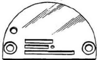
THROAT PLATE AND FEED DOG COMBINATIONS FOR STYLES 61400 A
| Part No. | Description |
| L28 | With .063 inch needle hole, for miscellaneous hemming operations; feed dog No. L29, presser foot No. L30 (.085 inch thick) |
| L29 | Teeth cut 16 per inch, for miscellaneous hemming operations; throat plate No. L28, presser foot No. L30 |
| L54 | With .063 inch needle hole, for miscellaneous seaming on leather; feed dog No. L55, presser foot No. 61420 BA (.085 inch thick) |
| L55 | Teeth cut 16 per inch, for miscellaneous seaming on leather; throat plate No. L54, presser foot No. 61420 BA |
| L118 | With .063 inch needle hole, for edge stitching shirts and dresses; feed dog No. L119, presser foot No. 61420 AM (.085 inch thick) |
| L119 | Teeth cut 22 per inch, for miscellaneous edge stitching with 1/2 inch margin; throat plate No. L118, presser foot No. 61420 AM |
| L143 | With .093 inch needle hole, for miscellaneous hemming operations, used with 3/16 inch plate hemmer; feed dog No. L206, presser foot No. L205 (.085 inch thick) |
| L206 | Teeth cut 16 per inch, for miscellaneous hemming operations, used with 3/16 inch plate hemmer; throat plate No. L143, presser foot No. L205 |
| L222 | With .063 inch needle hole, for top stitching collars of dress shirts; feed dog No. L223, presser foot No. L768 (.085 inch thick) |
| L223 | Teeth cut 16 per inch, for top stitching collars of dress shirts; throat plate No. L222, presser foot No. L768 |
| L287 | With .063 inch needle hole, for edge stitching coats and vests; feed dog No. 61305 G, presser foot No. 61320 (.085 inch thick) |
| L369 | Teeth cut 22 per inch, for hemming handkerchiefs; throat plate No. L391, presser foot No. 61320 AJ |
| L391 | With .063 inch needle hole, for hemming handkerchiefs; feed dog No. L369, presser foot No. 61320 AJ (.085 inch thick) |
| L519 | With .073 inch needle hole, for edge stitching sack coats and similar operations; feed dog No. L520, presser foot No. L518 (.085 inch thick) |
| L520 | Teeth cut 14 per inch, for edge stitching sack coats; throat plate No. L519, presser foot No. L518 |
| L579 | Teeth cut 22 per inch, for edge stitching pockets; throat plate No. L580, presser foot No. 61220 W |
| L580 | With .063 inch needle hole, for edge stitching pockets and similar operations; feed dog No. L579, presser foot No. 61220 W (.085 inch thick) |
| L936 | With .063 inch needle hole, for quilting operation; feed dog No. 61405 V, presser foot No. L298 (.085 inch thick) |
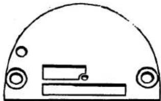
| 61205 | Teeth cut 16 per inch, for setting pockets on shirts and miscellaneous operations on house dresses; throat plate No. 61224-063, presser feet Nos. 61220 J, 62320 AH |
| 61224-063 | With .063 inch needle hole, for seaming house dresses; also in size .093 inch needle hole for setting pockets in work and dress pants; feed dog No. 61205, presser feet Nos. 61220 J, 61320 AH (.085 inch thick) |
| 61305 G | Teeth cut 16 per inch, for edge stitching coats and vests; throat plates Nos. L287, 61324 F-093, presser feet Nos. 61320, L290 |
| 61405 V | Teeth cut 12 per inch, for quilting operations; throat plate No. L936, presser foot No. L298 |
| 61405 Y | Teeth cut 22 per inch, for hemming shirts; throat plate No. 61424 Y-063, presser foot No. 61220 J |
| 61424 Y-063 | With .063 inch needle hole, for hemming shirts; also in size .073 inch needle hole; feed dog No. 61405 Y, presser foot No. 61220 J (.085 inch thick) |
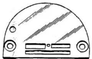
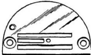
natural_image
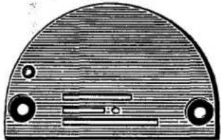
Simple line drawing of a semi-circular object with internal rectangular shapes and circular ports (no text or symbols)61224 E
61205 E

natural_image
Simple line drawing of a semi-circular mechanical component with holes and a slot (no text or symbols)61324 P
61305 P
natural_image
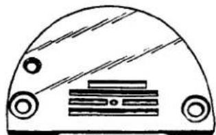
Simple line drawing of a semi-circular object with two circular ports and a central rectangular component (no text or symbols)61224 F
61205 D
natural_image
Top-down view of a curved mechanical component with internal components (no text or symbols visible)61324

61305
natural_image
Simple line drawing of a semi-circular object with internal components (no text or symbols)61424 J
61405 J

natural_image
Simple line drawing of a semi-circular mechanical component with internal features (no text or symbols)61324E
61305E
natural_image
Simple line drawing of a semi-circular object with circular tops and horizontal bars (no text or symbols)61424 L
61405 L

natural_image
Simple line drawing of a semi-circular mechanical component with no text or symbols61324 F

61305 G

natural_image
Simple line drawing of a semi-circular object with two circular ends and a central rectangular element (no text or symbols)61424 M
61405 M

natural_image
Simple line drawing of a dome-shaped object with internal components (no text or symbols)61324 L

61305 M
natural_image
Simple line drawing of a semi-circular object with internal lines and circular elements (no text or symbols)61424 P
61405 P

natural_image
Simple line drawing of a dome-shaped object with circular holes and a rectangular slot (no text or symbols)61424 R
61405 R
natural_image
Simple line drawing of a dome-shaped object with circular and rectangular elements (no text or symbols)61424 U

61405 U
THROAT PLATE AND FEED DOG COMBINATIONS FOR STYLE 61400 A
| Part No. | Description |
| 61205 D | Teeth cut 16 per inch, for setting pockets on shirts; throat plate No. 61224 F-073, presser feet Nos. 61320 AH, 61320 AJ |
| 61205 E | Teeth cut 16 per inch, for hemming work shirts; throat plate No. 61224 E-063, presser foot No. 61420 BN |
| 61224 E-063 | With .063 inch needle hole, for hemming work shirts; feed dog No. 61205 E, presser foot No. 61420 BN (.085 inch thick) |
| 61224 F-063 | With .063 inch needle hole, for setting pockets of dress shirts; also in sizes .083, .093 inch needle holes for work shirts; feed dog No. 61205 D, presser feet Nos. 61320 AH, 61320 AJ (.085 inch thick) |
| 61305 | Teeth cut 16 per inch, for miscellaneous operations on cotton and wool trousers; throat plate No. 61324-093, presser foot No. 61320 B |
| 61305 E | Teeth cut 16 per inch, for miscellaneous operations on coats and pants; throat plate No. 61324 E-073, presser foot No. L266 |
| 61305 G | Teeth cut 16 per inch, for edge stitching coats and vests; throat plate No. L287 or 61324 F-093, presser foot No. 61320 or L290 |
| 61305 M | Teeth cut 12 per inch, for seaming heavy coats and trousers; throat plate No. 61324 L-093, presser foot No. 61320 S |
| 61305 P | Teeth cut 16 per inch, for edge stitching zipper tabs; throat plate No. 61324 P-093, presser foot No. 61420 BE |
| 61324-063 | With .063 inch needle hole, for miscellaneous operations on cotton and wool trousers; also in sizes .073, .093 inch needle holes; feed dog No. 61305, presser foot No. 61320 B (.085 inch thick) |
| 61324 E-063 | With .063 inch needle hole, for miscellaneous operations on coats and pants; also in sizes .073, .093 inch needle holes; feed dog No. 61305 E, presser foot No. L266 (.085 inch thick) |
| 61324 F-063 | With .063 inch needle hole, for edge stitching coats and similar garments; also in size .093 inch needle hole; feed dog No. 61305 G, presser foot No. L290 (.085 inch thick) |
| 61324 L-093 | With .093 inch needle hole, for seaming heavy coats, trousers and similar operations; feed dog No. 61305 M, presser foot No. 61320 S (.085 inch thick) |
| 61324 P-093 | With .093 inch needle hole, for edge stitching zipper tabs and similar operations; feed dog No. 61305 P, presser foot No. 61420 BE (.085 inch thick) |
| 61405 J | Teeth cut 22 per inch, for top stitching shirt collars; throat plate No. 61424 J-063, presser foot No. 61420 AH |
| 61405 L | Teeth cut 16 per inch, for binding rayon material; throat plate No. 61424 L-063, presser foot No. 61420 BE |
| 61405 M | Teeth cut 22 per inch, for attaching yokes to shirts; throat plate No. 61424 M-063, presser foot No. 61420 BD |
| 61405 P | Teeth cut 14 per inch, for hemming high back overall suspenders; throat plate No. 61424 P-093, presser foot No. 61320 C |
| 61405 R | Teeth cut 16 per inch, for sewing zipper tabs to pants flies; throat plate No. 61424 R-073, presser foot No. 61420 V |
| 61405 U | Teeth cut 16 per inch, for miscellaneous seaming on medium weight materials; throat plate No. 61424 U-093, presser foot No. 61220 P |
| 61424 J-063 | With .063 inch needle hole, for top stitching shirt collars; feed dog No. 61405 J, presser foot No. 61420 AH (.085 inch thick) |
| 61424 L-063 | With .063 inch needle hole, for binding rayon; feed dog No. 61405 L, presser foot No. 61420 BE (.085 inch thick) |
| 61424 M-063 | With .063 inch needle hole, for attaching yokes to shirts; feed dog No. 61405 M, presser foot No. 61420 BD (.085 inch thick) |
| 61424 P-093 | With .093 inch needle hole, for hemming high back overall suspenders; feed dog No. 61405 P, presser foot No. 61320 C (.085 inch) |
| 61424 R-073 | With .073 inch needle hole, for sewing zipper tabs to pants flies; feed dog No. 61405 R, presser foot No. 61420 V (.085 inch thick) |
| 61424 U-093 | With .093 inch needle hole, for general seaming medium weight work; feed dog No. 61405 U, presser foot No. 61220 P (.085 inch thick) |
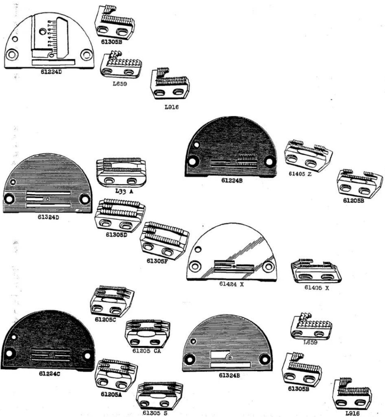
THROAT PLATE AND FEED DOG COMBINATIONS FOR STYLE 61400 A
| Part No. | Description |
| L33 A | Teeth cut 32 per inch, for tacking flies to overalls; throat plate No. 61324 D-063, presser foot No. 61320 Q |
| L659 | Teeth cut 10 per inch, for binding on melton and similar operations; throat plates Nos. 61224 D-073, 61324 B-093, presser feet Nos. 61220 H, 61320 |
| L916 | Teeth cut 22 per inch, for sewing bias strips on dresses and similar material; throat plates Nos. 61224 D-063, 61324 D-063, presser foot No. 61220 H |
| 61205 A | Teeth cut 16 per inch, for plain seaming on work shirts, dress and semi-dress pants; throat plate No. 61224 C-073, presser feet Nos. 61220 J, 61320 AB |
| 61205 B | Teeth cut 16 per inch, for hemming work shirts, dresses and similar garments; throat plate No. 61224 B-063, presser feet Nos. 61220 B, 61220 C |
| 61205 C | Teeth cut 22 per inch, for plain seaming ondress shirts, blouses, dresses and other light material; throat plates Nos. 61224 C-043, 61224 C-063, presser foot No. 61220 J |
| 61205 CA | Teeth cut 22 per inch, for hemming shirts, using hemmer No. L96, throat plate No. 61224 C-073, presser foot No. 61220 J |
| 61224 B-063 | With .063 inch needle hole, for hemming house dresses; also in size .093 inch needle hole for work shirts; feed dogs Nos. 61205 B, 61405 Z, presser feet Nos. 61220 B, 61220 C (.085 inch thick) |
| 61224 C-063 | With .063 inch needle holes for seaming dresses; also in sizes .043, .073, .083 inch needle holes for seaming work shirts and dress pants; feed dogs Nos. 61205 A, 61205 C, 61205 CA, 61305 S, presser feet Nos. 61220 C, 61220 J, 61320 AB (.085 inch thick) |
| 61224 D-063 | With .063 inch needle hole, for binding operations, used with English type binder; also in size .073 inch needle hole; feed dog Nos. 61305 B, L659, L916, presser feet Nos. 61220 H, 61320 (.085 inch thick) |
| 61305 B | Teeth cut 16 per inch, for edge stitching on suit coats and vests; throat plate No. 61324 B-063, presser foot No. 61320 |
| 61305 D | Teeth cut 14 per inch, for miscellaneous seaming operations; throat plate No. 61324 D-093, presser foot No. 61320 AA |
| 61305 F | Teeth cut 16 per inch, for miscellaneous operations on light weight material; throat plate No. 61324 D-073, presser foot No. 61320 AA |
| 61305 S | Teeth cut 32 per inch, for hemming work shirts; throat plates Nos. 61224 C-043, 61224 C-073, presser feet Nos. 61220 C, 61420 BB |
| 61324 B-063 | With .063 inch needle hole, for edge stitching on suits, coats and vests; also in sizes .073, .083, .093 inch needle holes; feed dogs Nos. 61305 B, L659, L916, presser foot No. 61320 (.085 inch thick) |
| 61324 D-063 | With .063 inch needle hole, for tacking flies to overalls and similar operations; also in sizes .073, .083, .093 inch needle holes; feed dogs Nos. L33 A, 61305 D, 61305 F, presser foot No. 61320 Q (.085 inch thick) |
| 61405 X | Teeth cut 22 per inch, for hemming on rayon; throat plate No. 61424 X-063, presser foot No. 61420 X |
| 61405 Z | Teeth cut 22 per inch, for edge stitching pockets on dresses, shirts and similar garments; throat plate No. 61224 B-063, presser foot No. 61420 AJ |
| 61424 X-063 | With .063 inch needle hole, for hemming rayon material; feed dog No. 61405 X, presser foot No. 61420 X (.085 inch thick) |
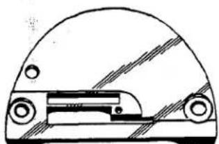
natural_image
Technical line drawing of a mechanical component with no visible text or symbolsL83 A

61305 U

natural_image
Technical line drawing of a mechanical component with no visible text or symbols61324 U
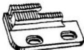
61305 U

natural_image
Simple line drawing of a semi-circular object with internal components (no text or symbols)L397
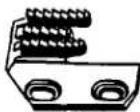
L398

natural_image
Cross-sectional diagram of a mechanical component with internal parallel bars and mounting holes (no text or symbols)61324C
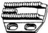
61305C

natural_image
Simple line drawing of a mechanical component with no text or symbolsL435
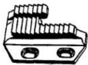
L436

natural_image
Simple line drawing of a dome-shaped object with internal compartments and circular ports (no text or symbols)61324 J
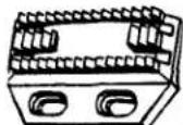
61305 K

natural_image
Simple line drawing of a dome-shaped object with circular elements and internal lines (no text or symbols)L437
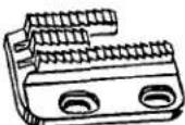
L438
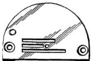
natural_image
Simple line drawing of a dome-shaped object with internal horizontal lines and circular elements (no text or symbols)61324 N
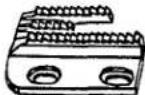
61305 N
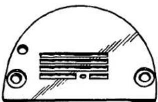
natural_image
Simple line drawing of a dome-shaped object with internal horizontal lines and circular ports (no text or symbols)L549
L550

natural_image
Simple line drawing of a semi-circular object with internal horizontal lines and circular ports (no text or symbols)61324 Q
61305 Q
THROAT PLATE AND FEED DOG COMBINATIONS FOR STYLE 61400 B
| Part No. | Description |
| L83 A | With .063 inch needle hole, for binding plastics; feed dog No. 61305 U, presser foot No. L82 A (.156 inch thick) |
| L397 | With .063 inch needle hole, for sewing sleeve facings to work shirts; feed dog No. L398, presser foot No. L440 (.250 inch thick) |
| L398 | Teeth cut 16 per inch, for binding operations on jackets and work shirts; throat plate No. L397, presser foot No. L440 |
| L435 | With .063 inch needle hole, for upholstery operations, 3/16 inch cord; feed dog No. L436, presser foot No. 61420 BC (.250 inch thick at back) |
| L436 | Teeth cut 12 per inch, for cording upholstery, 3/16 inch cord; throat plate No. L435, presser feet No. 61420 BC |
| L437 | With .083 inch needle hole, for binding operation on jackets; feed dog No. L438, presser foot No. L440 (.190 inch thick at back) |
| L438 | Teeth cut 16 per inch, for binding operations on jackets and work shirts; throat plate No. L437, presser foot No. L440 |
| L549 | With .073 inch needle hole, for attaching sleeve facings to work shirts; feed dog No. L550, presser foot No. 61420 H (.125 inch thick) |
| L550 | Teeth cut 16 per inch, for attaching sleeve facings to work shirts; throat plate No. L549, presser foot No. 61420 H |
| 61305 C | Teeth cut 14 per inch, for hemming high back overall suspenders; throat plate No. 61324 C-093, presser foot No. 61320 C |
| 61305 K | Teeth cut 12 per inch, for seaming heavy weight trousers, coats and similar garments; throat plate No. 61324 J-093, presser foot No. 61320 S |
| 61305 N | Teeth cut 16 per inch, for miscellaneous operations on work shirts; throat plate No. 61324 N-073, presser foot No. 61320 R |
| 61305 Q | Teeth cut 16 per inch, for pants fly operation, using folder No. L186; throat plate No. 61324 Q-073, presser foot No. 61220 |
| 61305 U | Teeth cut 22 per inch, for hemming work shirts and binding plastics; throat plate No. L83 A or 61324 U-063, presser foot No. L82 A or 61420 BN |
| 61324 C-083 | With .083 inch needle hole for hemming high back overall suspenders; also in sizes .093, .125 inch needle holes; feed dog No. 61305 C, presser foot No. 61320 C (.125 inch thick) |
| 61324 J-093 | With .093 inch needle hole, for seaming heavy weight trousers, coats and similar garments; feed dog No. 61305 K, presser foot No. 61320 S (.125 inch thick) |
| 61324 N-063 | With .063 inch needle hole, for miscellaneous operations on work shirts; also in sizes .073, .093 inch needle holes; feed dog No. 61305 N, presser foot No. 61320 R (.125 inch thick) |
| 61324 Q-073 | With .073 inch needle hole, for pants fly operations, using folder No. L186; feed dog No. 61305 Q, presser foot No. 61220 (.125 inch thick) |
| 61324 U-063 | With .063 inch needle hole, for hemming work shirts; feed dog No. 61305 U, presser foot No. 61420 BN (.156 inch thick) |
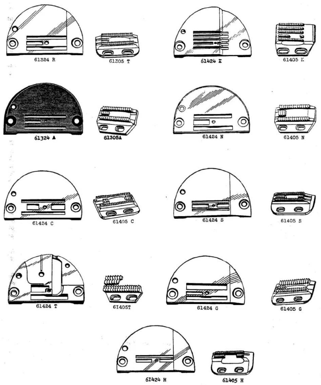
THROAT PLATE AND FEED DOG COMBINATIONS
FOR STYLE 61400 B
| Part No. | Description |
| 61305 A | Teeth cut 14 per inch, for miscellaneous operations on work pants, dungarees and overalls; throat plate No. 61324 A-093, presser foot No. 61220 P |
| 61305 T | Teeth cut 22 per inch, for miscellaneous seaming operations on coats and pants; throat plate No. 61324 R-093, presser foot No. 61220 P |
| 61324 A-063 | With .063 inch needle hole, for miscellaneous operations on work pants, dungarees and overalls; also in size .093, .125 inch needle holes; feed dog No. 61305 A, presser foot No. 61220 P (.125 inch thick) |
| 61324 R-073 | With .073 inch needle hole, for seaming operations on coats and pants; also in size .093 inch needle hole; feed dog No. 61305 T, presser foot No. 61220 P (.125 inch thick) |
| 61405 C | Teeth cut 16 per inch, for sewing pocket facings with chaining between pockets; throat plate No. 61424 C-093, presser foot No. 61420 C |
| 61405 G | Teeth cut 14 per inch, for cording couch covers; throat plate No. 61424 G-093, presser foot No. L189 |
| 61405 H | Teeth cut 22 per inch, for binding and hemming flannel shirts; throat plate No. 61424 H-063, presser foot No. L563 |
| 61405 K | Teeth cut 16 per inch, for sleeve facings on sport and work shirts; throat plate No. 61424 K-063, presser foot No. 61420 H |
| 61405 N | Teeth cut 14 per inch, for miscellaneous operations on denim, canvas and other heavy materials; throat plate No. 61424 N-093, presser foot No. 61320 AA |
| 61405 S | Teeth cut 22 per inch, for run stitching collar operations; throat plate No. 61424 S-063, presser foot No. 61420 BJ |
| 61405 T | Teeth cut 16 per inch, for miscellaneous binding operations on heavy weight materials; throat plate No. 61424 T-093, presser foot No. 61220 H |
| 61424 C-093 | With .093 inch needle hole, for sewing on pocket facings, and chain-ing between pockets; feed dog No. 61405 C, presser foot No. 61420 C (.125 inch thick) |
| 61424 G-093 | With .093 inch needle hole, for cording couch covers and similar operations; feed dog No. 61405 G; presser foot No. L189 (.125 inch thick) |
| 61424 H-063 | With .063 inch needle hole, for binding and hemming on flannel shirts; feed dog No. 61405 H, presser foot No. L563 (.125 inch thick) |
| 61424 K-063 | With .063 inch needle hole, for sleeve facings on sport and work shirts; feed dog No. 61405 K, presser foot No. 61420 H (.109 inch thick at front, .203 inch thick at back) |
| 61424 N-093 | With .093 inch needle hole, for miscellaneous operations on denim, canvas and other heavy weight material; feed dog No. 61405 N, presser foot No. 61320 AA (.125 inch thick) |
| 61424 S-063 | With .063 inch needle hole, for run stitching collar operation on dress and work shirts; feed dog No. 61405 S, presser foot No. 61420 BJ (.125 inch thick) |
| 61424 T-093 | With .093 inch needle hole, for miscellaneous binding operations; feed dog No. 61405 T, presser foot No. 61220 H (.125 inch thick) |

natural_image
Simple line drawing of a dome-shaped object with internal components (no text or symbols)61424 F
61405 F
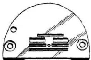
natural_image
Simple line drawing of a dome-shaped object with internal components (no text or symbols)61434 E
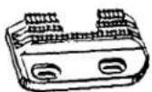
61405 E
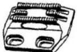
61205C
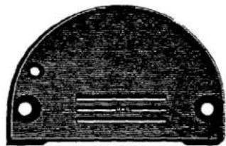
natural_image
Close-up of a semi-circular mechanical component with four holes and internal grooves (no text or symbols visible)61224C

612054
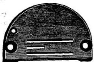
natural_image
Close-up of a curved mechanical component with circular holes and internal markings (no visible text or symbols)61324A
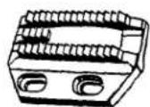
61305A
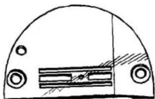
natural_image
Simple line drawing of a dome-shaped object with two circular holes and internal horizontal stripes (no text or symbols)61424 S
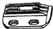
61405 S

natural_image
Technical line drawing of a mechanical component with no visible text or symbols61424 G
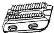
61405 G
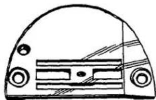
natural_image
Simple line drawing of a dome-shaped object with internal horizontal lines and circular ports (no text or symbols)61324 J

61305 K

natural_image
Pure technical diagram of a mechanical component with no text or symbols61424 A
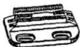
61405 A

natural_image
Simple line drawing of a semi-circular object with two circular ports and horizontal stripes (no text or symbols)C1424 B
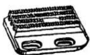
61405 B
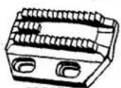
61305A

natural_image
Simple line drawing of a semi-circular mechanical component with internal grooves and mounting holes (no text or symbols)61324 R

61305 T
THROAT PLATE AND FEED DOG COMBINATIONS FOR STYLES 61400 N, 61400 P, 61400 R, 61400 S
| Part No. | Description |
| 61205 A | Teeth.cut 16 per inch, for sewing on hippocet cord, work and dress pants, throat plate No. 61224 C, presser feet Nos. 61320 AL, 61420 AA, top feed Nos. 61439 S, 61439 X |
| 61205 C | Teeth cut 22 per inch, for hemming and attaching collar bands to work and dress shirts; throat plate No. 61224 C, presser feet Nos. 61320 AM, 61420 BK, top feed Nos. 61439 N, 61439 X, L925 |
| *61224 C-063 | With .063 inch needle hole, for attaching collar bands to work and dress shirts, and sewing on hip pocket cord to work and dress pants; also in sizes .043, .073, .083 inch needle holes; feed dog Nos. 61205 A, 61205 C, presser feet Nos. 61420 AA, 61420 BK, 61320 AL, 61320 AM, top feed Nos. 61439 N, 61439 S, 61439 X, L925 |
| 61305 A | Teeth cut 14 per inch, for top stitching waistbands to work pants; throat plate Nos. 61324 A, 61324 R, presser foot No. 61420 J, top feed No. 61439 U |
| 61305 K | Teeth cut 12 per inch, for sleeve facing and hemming sport shirts; throat plate No. 61324 J, presser foot No. L926, top feed No. 61439 T |
| 61305 T | Teeth cut 22 per inch, for seaming on two or more ply materials; throat plate No. 61324 R, presser feet Nos. L39 A, 61320 AL, top feed No. 61439 S |
| 61324 A-063 | With .063 inch needle hole, for top stitching waistbands to work pants; also in sizes .093, .125 inch needle holes; feed dog No. 61305 A, presser foot No. 61420 J, top feed No. 61439 U |
| 61324 J-093 | With .093 inch needle hole, for sleeve facing and hemming sport shirts; feed dog No. 61305 K, presser foot No. L926, top feed No. 61439 T |
| 61324 R-073 | With .073 inch needle hole, for seaming heavy materials two or more plies; also in size .093 inch needle hole; feed dog Nos. 61305 A, 61305 T, presser feet Nos. 61320 AL, L39 A, top feed No. 61439 S |
| 61405 A | Teeth cut 32 per inch, for top stitching zippers to rayon; throat plate No. 61424 A, presser foot No. 61420 BK, top feed No. 61439 W |
| 61405 B | Teeth cut 22 per inch, for attaching sleeve facings to work shirts, jackets and children's garments; throat plate No. 61424 B, presser feet Nos. 61420 AA, 61420 AB, top feed Nos. 61439 T, 61439 V, L925 |
| 61405 E | Teeth cut 22 per inch, for attaching waistbands to trousers; throat plate No. 61424 E, presser foot No. 61420 BK, top feed No. 61439 S |
| 61405 F | Teeth cut 22 per inch, for piping pillow slips; throat plate No. 61424 F, presser foot No. L17 A, top feed No. 61439 V |
| 61405 G | Teeth cut 14 per inch, for hemming and seaming on heavy wool shirts and pants, throat plate No. 61424 G, presser feet Nos. 61320 X, L926, top feed Nos. 61439 T, L955 |
| 61405 S | Teeth cut 22 per inch, for hemming bottoms of sport shirts; throat plate No. 61424 S, presser foot No. 61420 AB, top feed No. 61439 T |
| 61424 A-063 | With .063 inch needle hole, for top stitching zippers to rayon material; feed dog No. 61405 A, presser foot No. 61420 BK, top feed No. 61439 W |
| 61424 B-063 | With .063 inch needle hole, for attaching sleeve facings to work shirts, jackets and children's garments; feed dog No. 61405 B, presser feet Nos. 61420 AA, 61420 AB, top feed Nos. 61439 T, 61439 V, L925 |
| *61424 E-063 | With .063 inch needle hole, for attaching waistbands to trousers; feed dog No. 61405 E, presser foot No. 61420 BK, top feed No. 61439 S |
| *61424 F-063 | With .063 inch needle hole, for piping pillow slips; feed dog No. 61405 F, presser foot No. L17 A, top feed No. 61439 V |
| 61424 G-093 | With .093 inch needle hole, for top stitching waistbands and hemming on shirts and pants; feed dog No. 61405 G, presser feet Nos. 61320 X, L926, top feed Nos. 61439 T, L955 |
| 61424 S-063 | With .063 inch needle hole, for hemming bottoms of sport shirts; feed dog No. 61405 S, presser foot No. 61420 AB, top feed No. 61439 T |
* Thin Throat Plates .085 inch thick for use on Styles 61400 N, 61400 P only. All other plates listed for use on Styles 61400 R, 61400 S
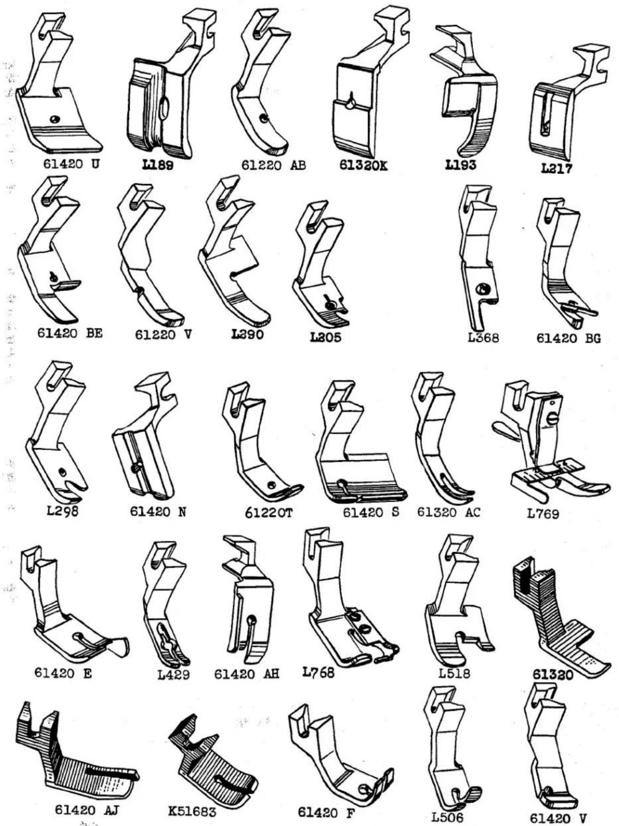
PRESSER FEET
| Part No. | Description |
| L189 | For cording couch covers, 1/4 inch cord groove 1/32 inch to right of needle; feed dog No. 61405 G, throat plate No. 61424 G |
| L193 | For edge stitching coats, right toe cut off at needle; feed dog No. 61305 B, throat plate No. 61324 B-073 |
| L205 | For miscellaneous hemming, used with 3/16 inch plate hemmer; feed dog No. L206, throat plate No. L143 |
| L217 | For braiding sport shirts and similar garments, 7/64 inch braiding groove in center of needle; feed dog No. 61205 A, throat plate No. 61224 C-083 |
| L290 | For edge stitching coats and similar garments; feed dog No. 61305 G, throat plate No. 61324 F-093 |
| L298 | For quilting operations; throat plate No. 61424 V, feed dog No. 61405 V |
| L368 | For hemming handkerchiefs, feed dog No. L369, throat plate No. L391 |
| L429 | For zipper tab operation; feed dog No. 61205, throat plate No. 61224 C-063 |
| L506 | For edge stitching light weight materials; feed dog No. 61205 C, throat plate No. 61224 C-063 |
| L518 | For edge stitching sack coats; feed dog No. L520, throat plate No. L519 |
| L768 | For top stitching collars; guide 3/16 inch to right of needle; feed dog No. L223, throat plate No. L222 (screw for guide No. 22738) |
| L769 | With adjustable guide for quilting, 1/16 inch to 7/8 inch margin to left of needle; feed dog No. 61405 M, throat plate No. 61424 M (spring release lever No. 61330 P, spring No. 61330 N, screw No. 22547 A) |
| K51683 | For attaching cuffs to shirts; feed dog No. 61305 A, throat plate No. 61324 A-093 |
| 61220 T | For hemming towels; feed dog No. 61205 A, throat plate No. 61224 C-073 |
| 61220 V | For zipper tab operations; feed dog No. 61205 A, throat plate No. 61224 C-073 |
| 61220 AB | For edge stitching; feed dog No. 61205 A, throat plate No. 61224 C-063 |
| 61320 | For edge stitching on men's suits, coats; feed dog No. 61305 B, throat plate No. 61324 B-093 |
| 61320 K | For shirring light weight house dresses; feed dog No. 61205 A, throat plate No. 61224 C-073 |
| 61320 AC | For attaching hook and eye strips to corsets; feed dog No. 61305 S, throat plate No. 61224 C-043 |
| 61420 E | For edge stitching, guide extends 1/4 inch to right of needle; feed dog No. 61305 A, throat plate No. 61324 A-093 |
| 61420 F | For hemming work shirts, used with plate hemmer; feed dog No. 61205 A, throat plate No. 61224 C-063 |
| 61420 N | For piping pajama fronts and collars, 3/32 inch prepared piping; feed dog No. 61205 A, throat plate No. 61224 C-063 |
| 61420 S | For attaching sleeve facing to work shirts, foot extends 3/4 inch to right of needle; feed dog No. 61405 K, throat plate No. 61424 K |
| 61420 U | For pants flies, one operation; folder No. L186, feed dog No. 61205 A, throat plate No. 61224 C-083 |
| 61420 V | For sewing zipper tabs to pants flies, 1/16 inch margin to left of needle; feed dog No. 61405 R, throat plate No. 61424 R |
| 61420 AH | For top stitching shirt collars, pajamas, 3/16 inch margin to right of needle; feed dog No. 61405 J, throat plate No. 61424 J-063 |
| 61420 AJ | For edge stitching pockets on dresses, shirts, 1/32 inch margin to right of needle; feed dog No. 61405 Z, throat plate No. 61224 B-063 |
| 61420 BE | For miscellaneous binding on rayon and similar material; feed dog No. 61305 P, throat plate No. 61324 P-063 |
| 61420 BG | For hemming bed sheets; feed dog No. 61205 C, throat plate No. 61224 C-063 |
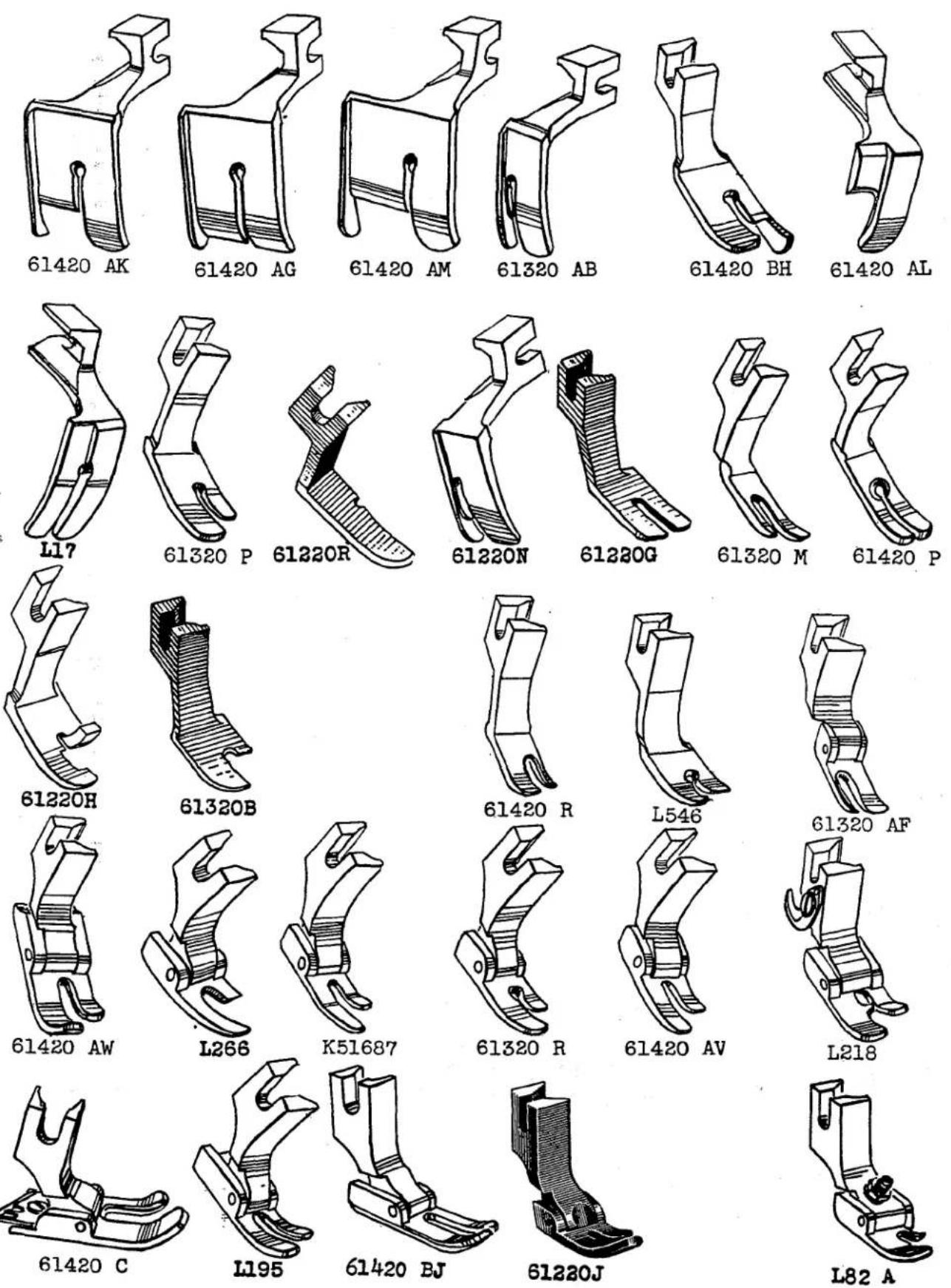
PRESSER FEET
| Part No. | Description |
| L17 | For edge stitching collars, left side of bottom .030 inch lower; feed dog No. 61205 A, throat plate No. 61224 C-073 |
| L82 A | For binding plastics; feed dog No. 61305 U, throat plate No. L83 A (adjusting screw No. 22840 A, lock nut No. 51430 F, hinge pin No. 61330 B-39) |
| L195 | For miscellaneous shirt operations; feed dog No. 61205 A, throat plate No. 61224 C-063 (shank No. 61330 AC, hinge pin No. 61330 B-29) |
| L218 | For edge stitching dress shirt collars; feed dog No. 61205 A, throat plate No. 61224 C-063 (pin No. 1741 A, knife No. 1741 B, screw No. 187 A) |
| L266 | For miscellaneous operations on suit pants and coats; feed dog No. 61305 E, throat plate No. 61324 E-073 (hinge pin No. 61330 B-35, shank No. 61330 AC) |
| L546 | For miscellaneous binding; feed dog No. L398, throat plate No. L397 |
| K51687 | For miscellaneous seaming on light weight material; feed dog No. 61205 C, throat plate No. 61224 C-063 (shank No. 61330 AC, hinge pin No. 61330 B-29) |
| 61220 G | For hemming work shirts, used with plate hemmer; feed dog No. 61205 A, throat plate No. 61224 C-063 |
| 61220 H | For miscellaneous binding operations on melton jackets; feed dog No. L659, throat plate No. 61224 D-093 |
| 61220 J | For seaming light and medium weight woven material, has spring for raising toe; feed dog No. 61205 C, throat plate No. 61224 C-063 (spring No. 61230 AK, shank No. 61330 AC, bottom No. 61330 Z, hinge pin No. 61330 B-31) |
| 61220 N | For attaching labels, guide 1/16 inch to right of needle; feed dog No. 61205 A, throat plate No. 61224 C-063 |
| 61220 R | For zipper tab operations; feed dog No. 61205 A, throat plate No. 61224 C-073 |
| 61320 B | For edge stitching on men's pants; feed dog No. 61305, throat plate No. 61324-093 |
| 61320 M | For attaching zippers to light weight garments; feed dog No. 61205 A, throat plate No. 61224 C-063 |
| 61320 P | For miscellaneous seaming; feed dog No. 61305 D, throat plate No. 61324 D-073 |
| 61320 R | For plain seaming operations on work shirts; feed dog No. 61305 N, throat plate No. 61324 N-073 (shank No. 61330 AC, bottom No. 61330 AF, hinge pin No. 61330 B-31) |
| 61320 AB | For edge stitching on pants flies, guide 1/16 inch to right of needle, feed dog No. 61205 A, throat plate No. 61224 C-073 |
| 61320 AF | For sewing zipper tabs to various type garments; feed dog No. 61205 A, throat plate No. 61224 C-063 |
| 61420 C | For sewing on pocket facing to trousers and chaining between pockets, foot equipped with chain cutting knife; feed dog No. 61405 C, throat plate No. 61424 C-093 (bottom No. 61430 C, screw No. 73 A, knife No. 61430 A, knife guard No. 61430 B, hinge pin No. 61330 B-35, spring No. 51930, shank No. 61330) |
| 61420 P | For tacking pants flies; feed dog No. 61205 C, throat plate No. 61224 C-063 |
| 61420 R | For sewing zipper tabs to pants flies; feed dog No. 61205 A, throat plate No. 61224 C-083 |
| 61420 AG | For edge stitching work jackets, 3/8 inch margin to right of needle; feed dog No. 61205 D, throat plate No. 61224 F-063 |
| 61420 AK | For edge stitching on light to heavy materials, 3/8 inch margin to right of needle; feed dog No. 61305 A, throat plate No. 61324 A-093 |
| 61420 AL | For edge stitching pants flies, 1/32 inch margin to left of needle; feed dog No. 61305 B, throat plate No. 61324 B-093 |
| 61420 AM | For edge stitching, 1/2 inch margin to right of needle; feed dog No. L119, throat plate No. L118 |
| 61420 AV | For miscellaneous seaming on dresses and shirts made of light weight woven materials; feed dog No. 61205 E, throat plate No. 61224 E-063 (spring No. 51930, hinge pin No. 61330 B-29) |
| 61420 AW | For miscellaneous seaming on dress pants and suits made of cotton and wool materials; feed dog No. 61305 C, throat plate No. 61324 C-093 (shank No. 61330) |
| 61420 BH | For edge stitching, guide extends 1/8 inch to right of needle; feed dog No. 61305 A, throat plate No. 61324 A-093 |
| 61420 BJ | For collar operation on dress shirts; feed dog No. 61405 S, throat plate No. 61424 S-063 (shank No. 61330, bottom No. 61330 T, hinge pin No. 61330 B-39) |

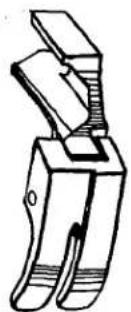
natural_image
Simple line drawing of a mechanical clamp or bracket (no text or symbols)L69
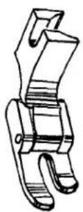
61320 Q
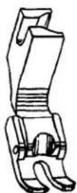
L95

natural_image
Technical line drawing of a mechanical clamp or bracket (no text or symbols)61320 AD
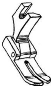
natural_image
Technical line drawing of a mechanical clamp or bracket (no text or symbols)61320 S

natural_image
Technical line drawing of a mechanical bracket or clamp (no text or symbols)61320 z
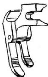
natural_image
Line drawing of a mechanical clamp or bracket component (no text or symbols)61320 AA
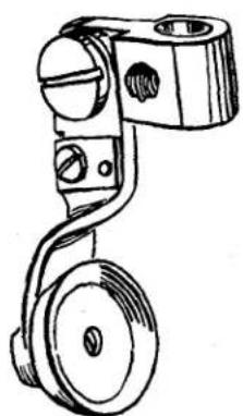
natural_image
Line drawing of a mechanical pulley system with two wheels and a handle (no text or symbols)61420 BA
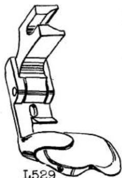
natural_image
Line drawing of a hand gripping a mechanical clip (no text or symbols)
natural_image
Technical line drawing of a mechanical clamp or bracket component (no text or symbols)L748

natural_image
Line drawing of a mechanical clamp or bracket device (no text or symbols)L408
PRESSER FEET
| Part No. | Description |
| L64 | For hemming overall suspender straps; feed dog No. 61305 M, throat plate No. 61324 L-093 (shank No. 61330) |
| L69 | For hemming overall suspenders, left side of bottom 1/16 inch lower, 1/16 inch to left of needle; feed dog No. 61205 A, throat plate No. 61324 C-063 (shank No. 61230 D, hinge pin No. 61330 B-29) |
| L72 | For edge stitching, right side of bottom 1/32 inch lower, 1/16 inch to right of needle; feed dog No. 61305 C, throat plate No. 61324 C-063 (shank No. 61330, hinge pin No. 61330 B-35) |
| L95 | For miscellaneous seaming operations; feed dog No. 61205 A, throat plate No. 61224 C-063 (shank No. 61330 AC, hinge pin No. 61330 B-29) |
| L313 | For edge stitching, left side of bottom 1/16 inch lower, 1/16 inch to left of needle; feed dog No. 61305 A, throat plate No. 61324 A-093 (shank No. 61330, hinge pin No. 61330 B-35) |
| L326 | For miscellaneous seaming, 5/16 inch feed surface in back of needle; feed dog No. 61305 B, throat plate No. 61324 B-093 (shank No. 61330 AC, hinge pin No. 61330 B-29) |
| L408 | For attaching yokes, 5/16 inch turned down fold; feed dog No. 61205 A, throat plate No. 61224 C-063 (shank No. 61230 D, hinge pin No. 61330 B-29) |
| L529 | For attaching yokes, 3/16 inch turned down fold; feed dog No. 61205 B, throat plate No. 61224 C-063 (hinge pin No. 61330 B-35) |
| L748 | For hemming dresses, material enters from left, 1/4 inch turned up hem; feed dog No. 61205 A, throat plate No. 61224 C-063 |
| 61220 P | For miscellaneous operations on medium weight materials, has spring for raising toe; feed dog No. 61305 K, throat plate No. 61324 A-093 (shank No. 61330, spring No. 51930, bottom No. 61330 AG, hinge pin No. 61330 B-35) |
| 61320 L | For hemming overall suspenders, guide 1/16 inch to left of needle; feed dog No. 61305 A, throat plate No. 61324 A-093 (bottom No. 61330 L, shank No. 61330, hinge pin No. 61330 B-35) |
| 61320 Q | For tacking flies to overalls; feed dog No. L33 A, throat plate No. 61324 D-063 (shank No. 61330, bottom No. 61330 R, hinge pin No. 61330 B-35) |
| 61320 S | For miscellaneous operations on heavy coats, trousers and similar operations; feed dog No. 61305 K, throat plate No. 61324 J-093 (shank No. 61330, bottom No. 61330 T, hinge pin No. 61330 B-35) |
| 61320 Z | For tacking pants flies; feed dog No. 61205 A, throat plate No. 61224 C-063 (hinge pin No. 61330 B-29, shank No. 61330 AC, bottom No. 61330 AA) |
| 61320 AA | For miscellaneous operations on denim, canvas and other heavy materials; feed dog No. 61305 C, throat plate No. 61324 C-093 (shank No. 61330, bottom No. 61330 AB, hinge pin No. 61330 B-35) |
| 61320 AD | For miscellaneous seaming operations on rayon and other light materials; feed dog No. 61205 C, throat plate No. 61224 C-063 (hinge pin No. 61330 B-31, spring No. 61230 AK, bottom No. 61330 AU, shank No. 61330 AC) |
| 61420 AD | For edge stitching coats, jackets, 3/16 inch margin to right of needle; feed dog No. 61205 A, throat plate No. 61224 C-083 (shank No. 61330, hinge pin No. 61330 B-39) |
| 61420 AE | For edge stitching overall suspenders, 1/16 inch margin to right of needle; feed dog No. 61305 C, throat plate No. 61324 C-093 (shank No. 61330, hinge pin No. 61330 B-35) |
| 61420 AF | For edge stitching shirts and dresses, 1/32 inch margin to right of needle; feed dog No. L224, throat plate No. 61224 B-063 (hinge pin No. 61330 B-29) |
| 61420 AX | For sewing zipper tabs to pants flies; feed dog No. 61205 E, throat plate No. 61224 E-063 (hinge pin No. 61330 B-29) |
| 61420 AY | For miscellaneous seaming on work and dress pants; feed dog No. 61205 A, throat plate No. 61224 C-063 (shank No. 61230 D, hinge pin No. 61330 B-29) |
| 61420 AZ | For sewing zipper tabs; feed dog No. 61205 E, throat plate No. 61224 E-063 (shank No. 61330, hinge pin No. 61330 B-29) |
| 61420 BA | For miscellaneous seaming on leather; feed dog No. L55, throat plate No. L54 (roller No. 1580 G-13, axle screw No. 22818, locking spring screw No. 22743, arm pivot screw No. 14076, spring guide screw No. 22561, spring No. 61430 L, screw No. 88)Also order one each No. 61257 G upper presser bar bushing, 61457 D lower presser bar bushing and 51957 D presser bar |

PRESSER FEET
Part No.
| L86 A | For welt seaming pants, one operation, split shank for guide; feed dog No. 61305 C, throat plate No. 61324 C-093 |
| L158 | For miscellaneous seaming, chaining section behind needle; feed dog No. 61305 A, throat plate No. 61324 A-093 (bottom No. 61330 V, yielding section No. 61330 W, spring No. 1230 B) |
| L220 | For cording couch covers, 3/16 inch cord groove 1/32 inch to left of needle; feed dog No. 61305 A, throat plate No. 61324 A-093 (shank No. 61330) |
| L293 | For miscellaneous house dress operations; feed dog No. 61205, throat plate No. 61224-063 (adjusting screw No. 51430 F, nut No. 22840 A) |
| L412 | For making pants flies with folder No. L464, feed dog No. 61305 A, throat plate No. 61324 A-093 (spring No. 51930, hinge pin No. 61330 B-29, shank No. 61230 D) |
| L440 | For binding operation on jackets and work shirts; feed dog No. L438, throat plate No. L437 |
| L505 | For miscellaneous hemming operations, guide on left of needle; feed dog No. 61305 C, throat plate No. 61324 C-093 (shank No. 61330, hinge pin No. 61330 B-35) |
| 61220 | For pants fly operations, using folder No. L186; feed dog No. 61305, throat plate No. 61324 Q-073 (shank No. 61330, bottom No. 61330 Y, hinge pin No. 61330 B-31) |
| 61220 K | For attaching sleeve facings to shirts; feed dog No. 61405 K, throat plate No. 61424 K-063 (spring No. 51930, shank No. 61330 AC, bottom No. 61330 AD, hinge pin No. 61330 B-29) |
| 61220 Q | For hemming pants flies; feed dog No. 61205 C, throat plate No. 61224 C-063 (spring No. 51930, bottom No. 61330 AE, shank No. 61330 AC, hinge pin No. 61330 B-29) |
| 61220 S | For stitching shirt pockets, right side yielding; feed dog No. 61205 A, throat plate No. 61224 C-063 (spring No. 51930, hinge pin No. 61330 B-35, bottom No. 61230 L, yielding section No. 61230 M, shank No. 61230 S) |
| 61220 W | For edge stitching pockets, right side yielding; feed dog No. L579, throat plate No. L580 (spring No. 51930, hinge pin No. 61330 B-35, bottom No. 61230 V, yielding section No. 61230 W, shank No. 61230 X) |
| 61320 C | For hemming high back overall suspenders; feed dog No. 61305 C, throat plate No. 61324 C-093 (shank No. 61330, bottom No. 61330 C, hinge pin No. 61330 B-29) |
| 61320 AG | For edge stitching shirt pockets, right side yielding; feed dog No. 61205 C, throat plate No. 61224 C-063 (shank No. 61330 AK, spring No. 51930, hinge pin No. 61330 B-35, bottom No. 61330 AJ, yielding section No. 61330 AL) |
| 61320 AH | For edge stitching shirt pockets, left side yielding; feed dog No. 61205 C, throat plate No. 61224 C-063 (yielding section No. 61330 AN, spring No. 51930, bottom No. 61330 AM, hinge pin No. 61330 B-31, shank No. 61330 AP) |
| 61320 AJ | For edge stitching shirt pockets, left side yielding; feed dog No. 61205 C, throat plate No. 61224 C-063 (spring No. 51930, hinge pin No. 61330 B-35, shank No. 61230 X, bottom No. 61330 AR, yielding section No. 61330 AS) |
| 61420 | For stitching down waistbands on pants, both sides yielding; feed dog No. 61305 A, throat plate No. 61324 A-093 |
| 61420 A | For second operation attaching collars, right side yielding; feed dog No. 61205 A, throat plate No. 61224 C-063 |
| 61420 B | For second operation attaching collars, left side yielding; feed dog No. 61205 A, throat plate No. 61224 C-063 |
| 61420 H | For attaching sleeve facings to shirts; feed dog No. 61405 K, throat plate No. 61424 K-063 (shank No. 61330 AH, adjusting screw No. 51430 F, nut No. 22840 A, hinge pin No. 61330 B-35) |
| 61420 M | For piping upholstery, furniture and automobile cushions, 5/32 inch piping; feed dog No. L436, throat plate No. L435 (hinge screw No. 22799 B) |
| 61420 T | For binding; feed dog No. 61305 B, throat plate No. 61324 B-063 (hinge adjusting screw nut No. 51430 F, screw No. 22840 A, hinge pin No. 61330 B-35) |
| 61420 AN | For setting shirt pockets, 1/32 inch margin; feed dog No. 61205 C, throat plate No. 61224 C-063 (bottom No. 61230 L, spring No. 51930, hinge pin No. 61330 B-35) |
| 61420 AP | For one operation pants fly, for medium weight materials; folder No. L495, feed dog No. 61305 A, throat plate No. 61324 A-093 (shank No. 61330, hinge pin No. 61330 B-35) |
| 61420 AR | For miscellaneous edge stitching, 1/32 inch margin; edge guide No. 61303, feed dog No. 61205 E, throat plate No. 61224 E-063 (hinge pin No. 61330 B-29) |
| 61420 AS | For miscellaneous operations on plastics; feed dog No. 61305 U, throat plate No. 61324 U-063 (nut No. 51430 F, adjusting screw No. 22840 A, shank No. 61330 AH, hinge pin No. 61330 B-29) |
| 61420 AT | For miscellaneous operations on silks, rayon and light weight materials; feed dog No. 61205 C, throat plate No. 61224 C-063 |
| 61420 BC | For cording upholstery, 3/16 inch cord groove to left of needle; feed dog No. L436, throat plate No. L435 (hinge screw No. 22799 B) |
| 61420 BN | For hemming work shirts, 1/16 inch margin to left of needle; feed dog No. 61205 CA, throat plate No. 61224 C-063 |
| 61420 BR | For miscellaneous seaming on plastics; feed dog No. 61305 U, throat plate No. 61324 U-063 (adjusting screw No. 22840 A, nut No. 51430 F) |
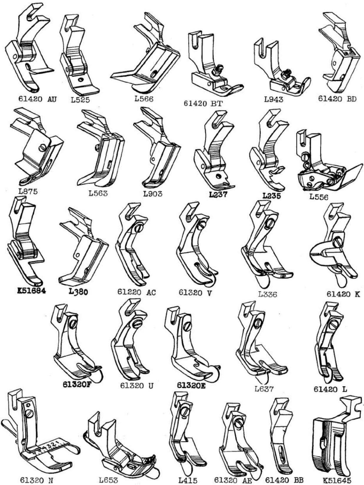
PRESSER FEET
| Part No. | Description |
| L235 | For miscellaneous hemming operations; feed dog No. 61305 A, throat plate No. 61324 A-093 (shank No. 61330, bottom No. 61330 B) |
| L237 | For miscellaneous binding or hemming; feed dog No. 61305 B, throat plate No. 61324 B-093 (shank No. 61330, hinge screw No. 61330 B-35) |
| L336 | For edge stitching, spring guide located 1/4 inch to left of needle; feed dog No. 61305 A, throat plate No. 61324 A-093 (spring guide No. L683, screw No. 187 A) |
| L380 | For cording and piping pajama coats; feed dog No. 61305 B, throat plate No. 61324 B-063 (shank No. 61330) |
| L415 | For edge stitching on heavy materials, 3/32 inch margin to left of needle; feed dog No. 61205 D, throat plate No. 61224 F-083 (spring guide No. 61330 E, screw No. 187 A) |
| L525 | For hemming cuffs and collar bands, used with hemmer folder; feed dog No. 61205 A, throat plate No. 61224 C-073 (shank No. 61230 D, hinge pin No. 61330 B-29) |
| L556 | For hemming heavy shirts and jackets, tractor type; feed dog No. 61305 A, throat plate No. 61324 A-093 (rear section No. 35730 C, yoke No. 25730 D, yoke screw No. 22799 E, hinge screw No. 22801, spring screw No. 226) |
| L563 | For hemming flannel shirts, left edge guide; feed dog No. 61405 H, throat plate No. 61424 H (shank No. 61330, hinge pin No. 61330 B-35, adjusting screw No. 51430 F, nut No. 22840 A) |
| L566 | For sleeve facing, left edge guide 5/16 inch from center of needle; feed dog No. 61405 K, throat plate No. 61424 K (shank No. 61330, adjusting screw No. 51430 F, nut No. 22840 A, hinge screw No. 61330 B-35) |
| L637 | For edge stitching, spring guide located 3/16 inch to left of needle; feed dog No. 61305 A, throat plate No. 61324 A-093 (spring guide No. 61330 F, screw No. 187 A) |
| L653 | For hemming, with plate hemmer, margin to right of needle; feed dog No. 61405 L, throat plate No. 61424 L (shank No. 61330 AC, hinge pin No. 61330 B-29, spring No. 51930, spring guide No. L122 A, screw No. 73 A) |
| L875 | For miscellaneous seaming; feed dog No. 61305 C, throat plate No. 61324 C-093 (spring No. 51930, shank No. 61330 AC, hinge pin No. 61230 B-29, chip guard screw No. 22798) |
| L903 | For cording pajama collars and similar garments, 1/16 inch cord groove 1/32 inch to left of needle; feed dog No. 61205 A, throat plate No. 61224 C-083 (hinge screw No. 22799 B) |
| L943 | For miscellaneous seaming on plastics; feed dog No. 61305 U, throat plate No. 61324 U-063 (adjusting screw No. 51430 F, nut 22840 A, hinge pin No. 61330 B-29) |
| K51645 | For cording upholstery, 9/32 inch cord groove 1/32 inch to left of needle; feed dog No. 61305 K, throat plate No. 61324 J-093 |
| K61584 | For binding operations, left edge guide; feed dog No. 61305 B, throat plate No. 61324 B-093 (shank No. 61330, hinge pin No. 61330 B-29) |
| 61220 AC | For edge stitching collar bands, guide 3/64 inch to right of needle; feed dog No. 61205 A, throat plate No. 61224 C-063 (guide No. 61230 U, screw No. 187 A) |
| 61320 E | For edge stitching overall pockets; guide 3/32 inch to right of needle; feed dog No. 61305 A, throat plate No. 61324 A-093 (guide No. 61330 E, screw No. 187 A) |
| 61320 F | For edge stitching overall pockets, guide located 3/16 inch to right of needle; feed dog No. 61305 A, throat plate No. 61324 A-093 (guide No. 61330 F, screw No. 187 A) |
| 61320 N | For edge stitching, adjustable guide; feed dog No. 61205 B, throat plate No. 61224 B-063 (main section No. 61330 M, spring No. 61330 N, spring release lever No. 61330 P, guide No. 61330 Q, screw No. 22547 A) |
| 61320 U | For edge stitching overalls, guide 1/16 inch to right of needle; feed dog No. 61305 A, throat plate No. 61224 C-063 (spring guide No. 61230 U, screw No. 187 A) |
| 61320 V | For edge stitching overall pockets; guide 1/8 inch to right of needle; feed dog No. 61305 A, throat plate No. 61324 A-093 (guide No. 61330 E, screw No. 187 A) |
| 61320 AE | For miscellaneous edge stitching, spring guide located 1/4 inch to right of needle; feed dog No. 61305 A, throat plate No. 61324 A-093 (guide No. 61330 F, screw No. 187 A) |
| 61420 K | For setting pockets, 1/16 inch margin to left of needle; feed dog No. 61305 A, throat plate No. 61324 A-093 (spring guide No. L357, screw No. 22561) |
| 61420 L | For setting pockets to work shirts, spring guide 1/16 inch to left of needle; feed dog No. 61205 C, throat plate No. 61224 C-083 (spring guide No. L594, screw No. 187 A) |
| 61420 AU | For hemming pajama coats, 5/8 inch hem, 9/16 inch margin to right of needle; feed dog No. 61405 K, throat plate No. 61424 K (shank No. 61330, hinge pin No. 61330 B-35) |
| 61420 BB | For miscellaneous seaming and hemming silk, rayon; feed dog No. 61205 C, throat plate No. L63 |
| 61420 BD | For yoking shirts, guide extends 1/32 inch to left of needle; feed dog No. 61405 M, throat plate No. 61424 M (shank No. 61330 AC, hinge pin No. 61330 B-29) |
| 61420 BT | For seaming plastics; feed dog No. 61305 U, throat plate No. 61324 U-063 (adjusting screw No. 51430 F, nut No. 22840 A) |
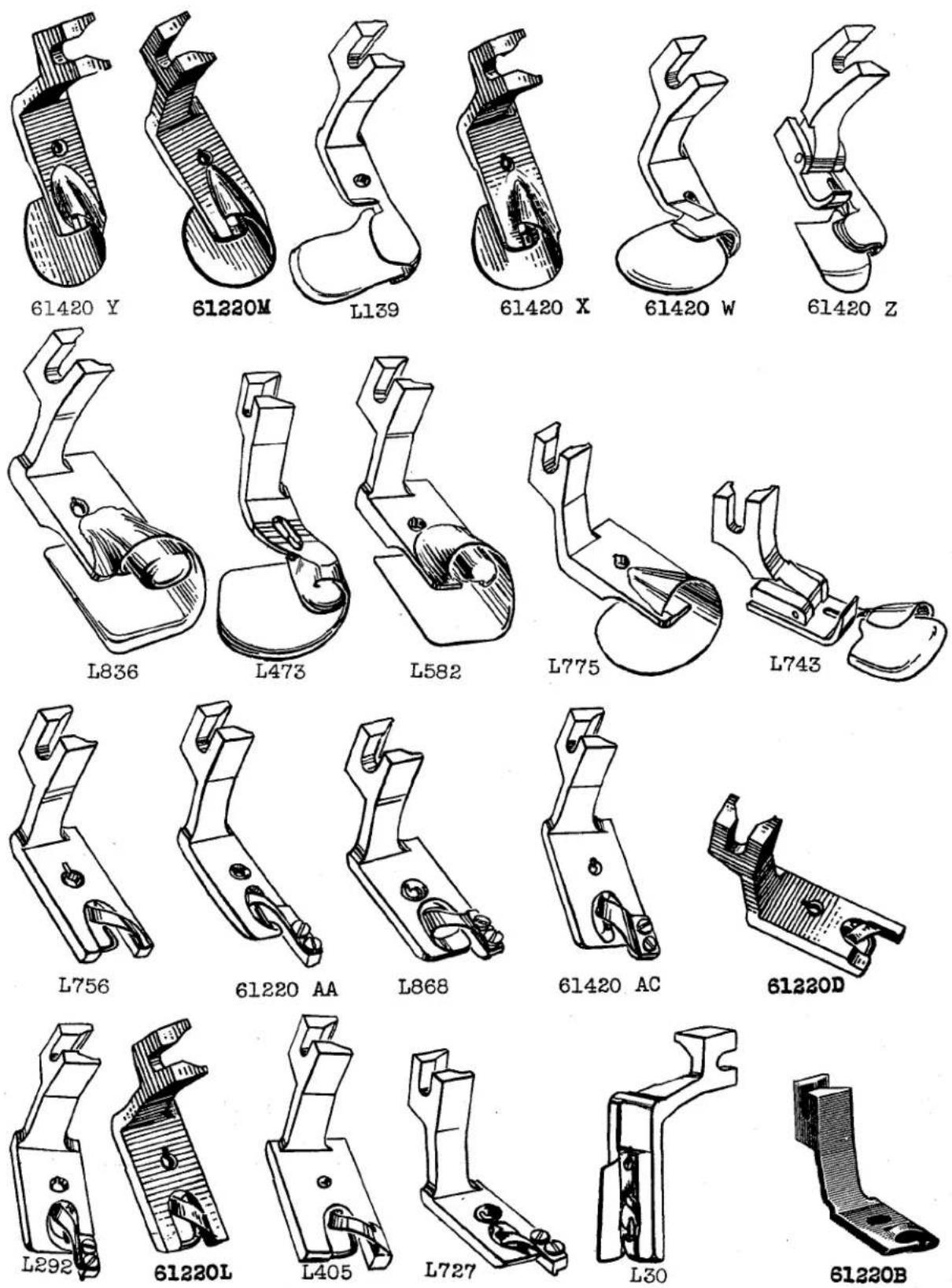
PRESSER FEET
| Part No. | Description |
| L30 | For hemming, 1/8 inch hem, has guide to fit in throat plate; feed dog No. L29, throat plate No. L28 (scroll No. L774) |
| L139 | For miscellaneous hemming, material enters from left, 3/16 inch turned down hem, feed dog No. 61205 C, throat plate No. 61224 C-063 |
| L292 | For hemming shirts, 3/16 inch hem; feed dog No. 61405 Z, throat plate No. 61224 B-063 (scroll pin No. 61230 C, screw No. 22738) |
| L405 | For hemming suede and light weight materials, 1/4 inch hem; feed dog No. 61205 C, throat plate No. 61224 C-063 (scroll pin No. 16230 C, scroll No. 61230-5/32) |
| L473 | For miscellaneous hemming, 5/32 inch turned up hem; feed dog No. 61205 A, throat plate No. 61224 C-063 |
| L582 | For hemming dresses, material enters from left, 3/8 inch turned up hem; feed dog No. 61205 C, throat plate No. 61224 C-063 |
| L727 | For hemming shirts, 3/32 inch hem; feed dog No. 61405 Z, throat plate No. 61224 B-063 (scroll pin No. 61230 C, screw No. 22738) |
| L743 | For hemming light canvas, 1/2 inch turned down hem; feed dog No. 61205 D, throat plate No. 61224 F-063 (shank No. 61330, hinge pin No. 61330 B-29) |
| L756 | For hemming shirts, 7/32 inch hem; feed dog No. 61205 C, throat plate No. 61224 C-063 (scroll pin No. 61230 J) |
| L775 | For miscellaneous hemming, material enters from left, 1/4 inch turned up hem; feed dog No. 61205 D, throat plate No. 61224 F |
| L836 | For hemming dresses, material enters from left, 1/2 inch turned up hem; feed dog No. 61205 A, throat plate No. 61224 C-063 |
| L868 | For hemming shirts, 1/4 inch hem; feed dog No. 61205 C, throat plate No. 61224 C-063 (scroll pin No. 61230 C, screw No. 22738) |
| 61220 B-1/8 | For hemming shirts; feed dog No. 61205 B, throat plate No. 61224 B-063 (scroll No. 61230 B-1/8, pin No. 61230 C) |
| 61220 B-5/32 | For hemming shirts; feed dog No. 61205 B, throat plate No. 61224 B-063 (scroll No. 61230 B-1/8, pin No. 61230 C) |
| 61220 D-1/8 | For hemming shirts; feed dog No. 61405 Z, throat plate No. 61224 B-063 (scroll No. 61230-5/32, pin No. 61230 J) |
| 61220 L-5/32 | For hemming shirts; feed dog No. 61205 B, throat plate No. 61224 B-063 (scroll No. 61230-5/32, pin No. 61230 J) |
| 61220 M-1/8 | For hemming dresses; feed dog No. 61205 C, throat plate No. 61224 C-063 |
| 61220 AA-1/8 | For hemming shirts; feed dog No. 61205 B, throat plate No. 61224 C-063 (scroll No. 61230 A-1/8, pin No. 61230 C, screw No. 22738) |
| 61420 W | For setting yokes and turning down hems on dresses, shirts and similar garments, 1/32 inch margin to right of needle; feed dog No. 61205 A, throat plate No. 61224 C-063 |
| 61420 X | For miscellaneous hemming, turned up hem, light weight material; feed dog No. 61205 C, throat plate No. 61224 C-063 |
| 61420 Y | For hemming dresses, light weight material, turned up 1/16 inch hem; feed dog No. 61205 C, throat plate No. 61224 C-063 |
| 61420 Z | For setting yokes on dress shirts, pajamas, 1/4 inch turned down fold; feed dog No. 61205 C, throat plate No. 61224 C-063 |
| 61420 AC | For 3/16 inch hem on work shirts; feed dog No. 61205 C, throat plate No. 61224 C-063 (scroll No. L603, screw No. 22738) |

PRESSER FEET AND BOTTOMS
| Part No. | Description |
| L175 | For hemming shirts, 1/8 inch hem; feed dog No. 61205 A, throat plate No. 61224 C-063 |
| L404 | For hemming shirts, 3/32 inch hem; feed dog No. 61205 A, throat plate No. 61224 B-063 |
| 35730 C | Rear Section, for presser foot No. L556 |
| 35730 D | Yoke, for presser foot No. L556 |
| 61220 C-1/8 | For hemming shirts; feed dog No. 61205 C, throat plate No. 61224 C-063 (scroll No. 61230-5/32) |
| 61220 C-5/32 | For hemming shirts; feed dog No. 61205 C, throat plate No. 61224 C-063 (scroll No. 61230-5/32) |
| 61220 C-3/16 | For hemming shirts; feed dog No. 61205 C, throat plate No. 61224 C-063 (scroll No. 61230-5/32) |
| 61220 C-1/4 | For hemming shirts; feed dog No. 61205 A, throat plate No. 61224 C-063 (scroll No. 61230-5/32) |
| 61230 L | Bottom, for presser feet Nos. 61220 S, 61420 AN |
| 61230 M | Yielding Section, for presser foot No. 61220 S |
| 61230 V | Bottom, for presser foot No. 61220 W |
| 61230 W | Yielding Section, for presser foot No. 61220 W |
| 61330 C | Bottom, for presser foot No. 61320 C |
| 61330 L | Bottom, for presser foot No. 61320 L |
| 61330 M | Main Section, for presser foot No. 61320 N |
| 61330 R | Bottom, for presser foot No. 61320 Q |
| 61330 T | Bottom, for presser foot No. 61320 S |
| 61330 V | Bottom Yielding Section, for presser foot No. L158 |
| 61330 W | Bottom, for presser foot No. L158 |
| 61330 Y | Bottom, for presser foot No. 61220 |
| 61330 Z | Bottom, for presser foot No. 61220 J |
| 61330 AA | Bottom, for presser foot No. 61320 Z |
| 61330 AB | Bottom, for presser foot No. 61320 AA |
| 61330 AD | Bottom, for presser foot No. 61220 K |
| 61330 AE | Bottom, for presser foot No. 61220 Q |
| 61330 AF | Bottom, for presser foot No. 61320 R |
| 61330 AG | Bottom, for presser foot No. 61220 P |
| 61330 AJ | Bottom, for presser foot No. 61320 AG |
| 61330 AL | Yielding Section, for presser foot No. 61320 AG |
| 61330 AM | Bottom, for presser foot No. 61320 AH |
| 61330 AN | Yielding Section, for presser foot No. 61320 AH |
| 61330 AR | Bottom, for presser foot No. 61320 AJ |
| 61330 AS | Yielding Section, for presser foot No. 61320 AJ |
| 61330 AU | Bottom, for presser foot No. 61320 AD |
| 61330 AW | Bottom, for presser foot No. 61320 AL |
| 61330 AX | Bottom, for presser foot No. 61320 AM |
| 61430 C | Bottom, for presser foot No. 61420 C |

PRESSER FEET SHANK, SPRINGS AND GUIDES
| Part No. | Description |
| 20 | Washer, for hemmer support Nos. K51623, K51626 |
| T29 | Thumb Nut, for edge guide assembly No. L367 |
| L122 A | Spring Guide, for presser foot No. L653 |
| L683 | Spring Guide, for presser foot No. L336 |
| L774 | Hemmer Scroll, for presser foot No. L30 |
| 1230 B | Spring, for presser foot No. L158 |
| 1580 G | Roller, 13/16 inch diameter, 3/16 inch face, for presser foot No. 61420 BA |
| 1741 A | Pin, for knife on presser foot No. L218 |
| 1741 B | Chain Cutting Knife, for presser foot No. L218 (screw No. 187 A) |
| 3346 A | Lever Spring, for attachment No. L627 |
| 6990 | Spring, for tilting bottom of presser foot No. L69 |
| 12957 E | Spring Washer, for plate hemmer No. L32; also Nos. L390, L394, L524, K51623 |
| 21657 E | Washer, for pivot screw on edge guide No. L367 |
| 28618 | Edge Guide Locking Spring, for presser foot No. 61320 D |
| 35772 H | Spring Washer, for swinging arm No. 23278 K |
| 51430 F | Hinge Adjusting Screw Nut, for presser foot No. 61420 AS; also Nos. 61330 AH, 61420 BR, 61420 BT, L563, L943 |
| 51930 | Spring, for tilting bottoms of presser feet |
| 52930 T | Spring, for presser foot No. 61420 AB |
| 61230-5/32 | Hemmer Scroll, for presser feet Nos. K51697, 61220 C-1/8, -5/32, -3/16, -1/4, 61220 D-18, 61220 L-5/32 |
| 61230 A-1/8 | Hemmer Scroll, for presser foot No. 61220 AA-1/8 |
| 61230 B-1/8 | Hemmer Scroll, for presser foot No. 61220 B-1/8, -5/32 |
| 61230 C | Scroll Pin, for presser feet Nos. L292, 61220 B-1/8, 61220 AA-1/8 |
| 61230 J | Scroll Pin, for presser feet Nos. 61220 D-1/8, 61220 L-5/32, L756 |
| 61230 S | Shank, for presser foot No. 61220 S |
| 61230 U | Spring Guide, for presser feet Nos. 61220 AC, 61320 U |
| 61230 X | Shank, for presser foot No. 61220 W |
| 61230 AK | Spring, for presser foot No. 61220 J |
| 61231 | Finger Guard, attaches to presser foot |
| 61231 A | Finger Guard, attaches to presser foot |
| 61303 D | Washer, for Nos. 61303, L378 |
| 61330 | Shank, for presser feet Nos. 61220 P, 61320 C, 61320 L, 61320 Q, 61320 S, 61320 AA, 61420 C, 61420 AD, 61420 AP, 61420 AU, 61420 AW, 61420 B, L64, L525, L563, L566, L926 |
| 61330 B-29 | Hinge Pin, 29/64 inch long |
| 61330 B-31 | Hinge Pin, 31/64 inch long |
| 61330 B-35 | Hinge Pin, 35/64 inch long |
| 61330 B-39 | Hinge Pin, 39/64 inch long |
| 61330 E | Spring Guide, for presser feet Nos. 61320 E, 61320 V |
| 61330 F | Spring Guide, for presser feet Nos. 61320 F, 61320 AE |
| 61330 N | Spring, for adjustable guide on presser foot No. 61320 N |
| 61330 P | Spring Release Lever, for presser foot No. 61320 N |
| 61330 Q | Adjustable Guide, for presser foot No. 61320 N |
| 61330 X | Shank, for presser foot No. 61420 AB |
| 61330 AC | Shank, for presser feet Nos. L266, 61220 A, 61220 J, 61220 K, 61220 Q, 61320 R, 61320 AD, 61420 BD |
| 61330 AH | Shank, for presser feet Nos. 61420 AS, 61420 D |
| 61330 AK | Shank, for presser foot No. 61320 AG |
| 61330 AP | Shank, for presser foot No. 61320 AH |
| 61330 AV | Shank, for presser foot No. 61320 AL |
| 61430 A | Knife, chain cutter for presser foot No. 61420 C |
| 61430 B | Knife Guard, for presser foot No. 61420 C |
| 61430 L | Spring, for roller presser foot No. 61420 BA |
| 61430 M | Spring Guide, for presser foot No. 61420 K |
| 61420 N | Spring Guide, for presser foot No. 61420 L |
| 61430 P | Scroll, for presser foot No. 61420 AC (screw No. 22738) |


natural_image
Simple line drawing of a mechanical component with a circular head and shaft (no text or symbols)PRESSER FEET AND TOP FEED ROLLERS FOR STYLES 61400 N, 61400 P, 61400 R, 61400 S
| Part No. | Description |
| L17 A | For piping pillow slips; foot has 1/16 inch groove to left of needle; feed dog No. 61405 F, throat plate No. 61424 F, top feed No. 61439 V (hinge pin No. 61330 B-29) |
| L39 A | For seaming on two or more plies material; feed dog No. 61305 T, throat plate No. 61324 R, top feed No. 61439 S (hinge pin No. 61330 B-29, spring No. 51930) |
| L925 | For sleeve facing and hemming bottom of sport shirts, width of roller .2031, diameter of roller 1 15/64 inches; feed dog Nos. 61205 C, 61405 B, throat plate Nos. 61224 C, 61424 B, presser feet Nos. 61420 AB, 61420 BK |
| L926 | For sleeve facing, hemming sport and woolen shirts; feed dog Nos. 61405 G, 61305 K, throat plate Nos. 61424 G, 61324 J, top feed No. 61439 T (bottom No. 61330, hinge screw No. 22799 B, toe guide No. 51230 P, screw No. 605) |
| L955 | For top stitching waistbands to work pants, width of roller .070 inch, diameter of roller 1 15/64 inches; feed dog No. 61405 G, throat plate No. 61424 G, presser foot No. 61320 X |
| 61320 X | For top stitching waistbands to work pants; feed dog No. 61405 G, throat plate No. 61424 G, top feed No. L955 |
| 61320 AL | For miscellaneous seaming on heavy material; feed dog Nos. 61205 A, 61305 T, throat plate Nos. 61224 C, 61324 R, top feed Nos. 61439 S, 61439 X (shank No. 61330 AV, bottom No. 61330 AW, hinge pin No. 61330 B-29) |
| 61320 AM | For attaching collar bands to dress shirts; feed dog No. 61205 C, throat plate No. 61224 C, top feed No. 61439 X (shank No. 61330 AX, bottom No. 61330 AV, hinge pin No. 61330 B-29) |
| 61420 J | For top stitching waistbands to work pants; feed dog No. 61305 A, throat plate No. 61324 A, top feed No. 61439 U |
| 61420 AA | For attaching sleeve facings on shirts and sewing cord to pockets of work and dress pants; feed dog Nos. 61205 A, 61205 C, 61405 B, throat plate Nos. 61224 C, 61424 B, top feed Nos. 61439 N, 61439 S, 61439 T |
| 61420 AB | For sleeve facing and hemming shirts, jackets, and children's garments; feed dog Nos. 61405 B, 61405 S, throat plate Nos. 61424 B, 61424 S, top feed Nos. 61439 T, 61439 V, L925 (bottom yielding section No. 61430 BA, shank No. 61330 X, yielding section spring No. 52930 T, hinge pin No. 61330 B-29) |
| 61420 BK | For attaching waistbands, hemming trousers, and sewing zippers to rayon material; feed dog Nos. 61205 C, 61405 A, 61405 E, throat plate Nos. 61424, 61424 A, 61424 E, top feed Nos. 61439 S, 61439 W, L925 (hinge pin No. 61330 B-29) |
| 61439 N | For attaching sleeve facings to work and dress shirts, width of roller 1 inch, diameter of roller 1.232 inches; feed dog No. 61205 C, throat plate No. 61224 C-063, presser foot No. 61420 AA |
| 61439 S | For sewing on waistbands and seaming on heavy material, width of roller .156 inch, diameter of roller 1 15/64 inches; feed dog Nos. 61205 A, 61405 E, 61305 T, throat plate Nos. 61224 C, 61324 R, 61424 E, presser foot Nos. 61320 AL, 61420 AA, 61420 BK, L39 A |
| 61439 T | For sleeve facing and hemming sport and heavy woolen shirts, width of roller .250 inch, diameter of roller 1 15/64 inches; feed dog Nos. 61305 K, 61405 B, 61405 G, throat plate Nos. 61324 J, 61424 B, 61424 G, presser feet Nos. 61420 AA, L926 |
| 61439 U | For stitching waistbands to work pants, width of roller .250 inch, diameter of roller 1 inch; feed dog No. 61305 A, throat plate No. 61324 A, presser foot No. 61420 J |
| 61439 V | For piping pillow slips, facing children's garments and jackets, width of roller .280 inch, diameter of roller 1 inch; feed dog Nos. 61405 F, 61405 V, throat plate Nos. 61424 B, 61424 F, presser feet Nos. 61420 AB, L17 A |
| 61430 W | For top stitching zippers to rayon, rubberized roller; width of roller .132 inch, diameter of roller 1 inch; feed dog No. 61405 A, throat plate No. 61424 A, presser foot No. 61420 BK |
| 61439 X | For attaching collar bands to work and dress shirts; width of roller .125 inch, diameter of roller 1 15/64 inches; feed dog No. 61205 C, throat plate No. 61224 C, presser foot No. 61320 AM |
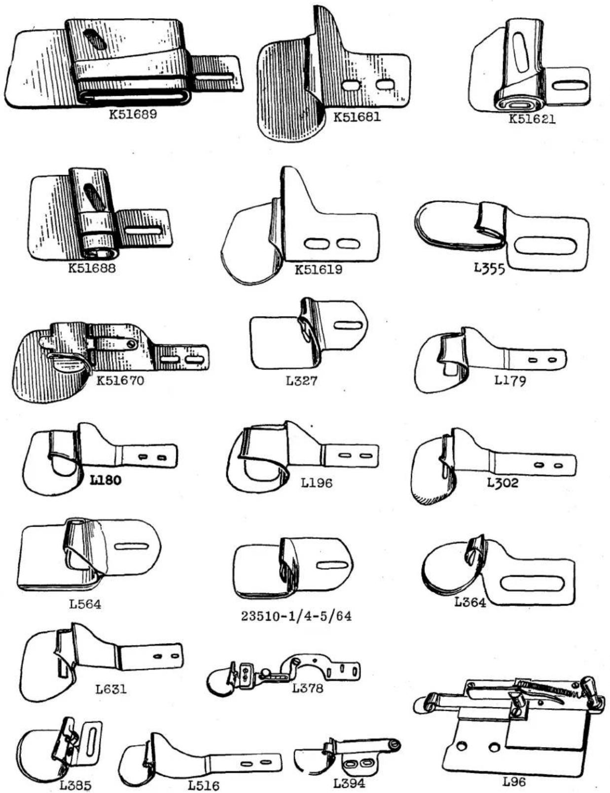
HEMMERS
| Part No. | Description |
| L96 | For hemming shirt tails, has retractable scroll, for 3/16 inch hem, feed dog No. 61205 CA, throat plate No. 61224 C-063, presser foot No. L95 (attaching screw No. 25 C, locking lever screw No. 22585, gib screw No. 90) |
| L179 | For hemming upholstery, 1/16 inch capacity, hem turned up, with underlap of 7/16 inch, finishes 1 inch, attached to swinging bracket No. K51623; feed dog No. 61205 A, throat plate No. 61224 C-073, presser foot No. 61220 T (screw No. 22570) |
| L180 | For hemming drapery material, 3/32 inch capacity, finishes 1 1/2 inches, attached to swinging bracket No. K51623; feed dog No. 61205 A, throat plate No. 61224 C-063, presser foot No. 61220 T (screw No. 22570) |
| L196 | For hemming drapery material, attached to swing-out bracket No. K51623, finishes 2 inches, 7/16 inch underlap; feed dog No. 61205 A, throat plate No. 61224 C-063, presser foot No. 61420 H (screw No. 22570) |
| L302 | For hemming drapery material, hem turned up with 5/16 inch underlap, finishes 1/2 inch, attached to swinging bracket No. K51623; feed dog No. 61205 A, throat plate No. 61224 C-073, presser foot No. 61220 T (screw No. 22570) |
| L327 | For hemming button facings on work shirts, 3/32 inch capacity, 1/2 inch finish, attached to swing-out bracket No. 23278 K; feed dog No. 61305 A, throat plate No. 61324 A-093, presser foot No. 61320 AH (screw No. 22585 A) |
| L355 | For hemming chambraywork shirts, finishes 11/16 inch; feed dog No. 61205 A, throat plate No. 61224 C-063, presser foot No. 61420 BN (screw No. 25 C) |
| L364 | Miscellaneous hemming operations on light weight material, capacity 1/16 inch, finishes 3/8 inch; feed dog No. 61205 C, throat plate No. 61224 C-063, presser foot No. 61320 AJ (screw No. 25 C) |
| L378 | For hemming shirts, 5/64 inch capacity, finishes 5/16 inch, swing-out type; feed dog No. 61205, throat plate No. 61224, presser foot No. 61420 BN (attaching screw No. 94, hemmer No. L385, hemmer attaching screw No. 90, thumb screw No. 22551, swinging bracket No. 61303 B, pivot screw No. 134, washer No. 61303 D) |
| L385 | For hemming shirts, 5/64 inch capacity, finishes 5/16 inch |
| L394 | For hemming high back overalls, 1/8 inch capacity, finishes 3/8 inch, swing-out type; feed dog No. 61305 A, throat plate No. 61324 A-093, presser foot No. 61320 L (attaching screw No. 25 C, pivot screw No. 22726, washer No. 12957 E) |
| L516 | For hemming rayon and cotton materials, capacity 1/16 inch, finishes 1/4 inch, attached to swing-out bracket No. K51623; feed dog No. 61205 C, throat plate No. 61224 C-063, presser foot No. 61420 AR (screw No. 22570) |
| L564 | For finishing button stays on medium weight sport shirts, 5/64 inch capacity, finishes 5/8 inch hem, attached to swing-out bracket No. 23278 K; feed dog No. 61205 A, throat plate No. 61224 C-063, presser foot No. 61220 W (screw No. 22585 A) |
| L631 | For hemming drapery material, 1/4 inch underlap, attached to swing-out bracket No. K51623, finishes 3/4 inch; feed dog No. 61205 A, throat plate No. 61224 C-073, presser foot No. 61220 Q (screw No. 22570) |
| 23510-1/4-5/64 | For hemming button stays on work shirts, 5/64 inch capacity, finishes 1/4 inch, attached to swinging bracket No. K51623; feed dog No. 61205 A, throat plate No. 61224 C-063, presser foot No. 61220 W (screw No. 22585 A) |
| K51619 | For hemming towels, 1/16 inch capacity, finishes 1/4 inch; feed dog No. 61205 A, throat plate No. 61224 C-063, presser foot No. 61220 T (screw No. 25 C) |
| K51621 | For hemming bed sheets, 1/16 inch capacity, finishes 1 inch, attached to swing-out bracket No. K51659; feed dog No. 61205 A, throat plate No. 61224 C-063, presser foot No. 61420 BG (screw No. 22711) |
| K51670 | For hemming house dresses, 5/64 inch capacity, finishes 1 1/2 inches, attached to swing-out bracket No. K51623; feed dog No. 61205, throat plate No. 61224, presser foot No. 61220 (screw No. 22570) |
| K51681 | For hemming towels, 5/16 inch capacity, finishes 3/32 inch; feed dog No. 61205 A, throat plate No. 61224 C-063, presser foot No. 61220 T (screw No. 25 C) |
| K51688 | For hemming bed sheets, with 3/8 inch underlap, finishes 1 inch, 1/16 inch capacity, attached to swing-out bracket No. K51659; feed dog No. 61205 A, throat plate No. 61224 C-063, presser foot No. 61420 BG (screw No. 22711) |
| K51689 | For hemming bed sheets, with 3/8 inch underlap, 1/16 inch capacity, finishes 3 inches, attached to swing-out bracket No. K51659; feed dog No. 61205 A, throat plate No. 61224 C-063, presser foot No. 61420 BG (screw No. 22711) |

HEMMERS
Part No.
Description
| L3 | For hemming overall suspender straps, 1/16 inch capacity, finishes 5/16 inch; feed dog No. 61305 C, throat plate No. 61324 C-093, presser foot No. 61320 L (screw No. 25 C) |
| L11 | For hemming rayon and similar materials, 3/64 inch capacity, finishes 5/16 inch; feed dog No. 61205 A, throat plate No. 61224 C-063, presser foot No. 61220 J (screw No. 25 C) |
| L122 | For hemming bed sheets, 1/16 inch capacity, finishes 2 inches, attached to swing-out bracket No. K51659; feed dog No. 61205 C, throat plate No. 61224 C-063, presser foot No. 61420 BG (screw No. 22711) |
| L123 | Plate Hemmer, for garments made of muslin, 1/16 inch capacity, finishes 1/8 inch; feed dog No. 61205 C, throat plate No. 61224 C-063, presser foot No. 61220 J (screw No. 25 C) |
| L154 | For hemming mesh curtains, 3/32 inch capacity, finishes 3 1/4 inches, attached to swing-out bracket No. K51623; feed dog No. 61205 C, throat plate No. 61224 C-063, presser foot No. 61220 (screw No. 22570) |
| L265 | For hemming men's shorts, 5/64 inch capacity, finishes 1/2 inch; feed dog No. 61205 C, throat plate No. 61224 C-063, presser foot No. 61420 BN (screw No. 25 C) |
| L433 | For miscellaneous hemming operations, 3/32 inch capacity, finishes 11/16 inch; feed dog No. 61305 D, throat plate No. 61324 D-093, presser foot No. 61420 S (screw No. 25 C) |
| L471 | For hemming sleeves and work shirts, finishes 1/2 inch; feed dog No. 61205 A, throat plate No. 61224 C-063, presser foot No. 61320 AJ (screw No. 22585 A) |
| L489 | For hemming sleeves and bottom of sport shirts, finishes 3/4 inch; feed dog No. 61205 A, throat plate No. 61224 C-063, presser foot No. 61220 (screw No. 22585 A) |
| L610 | For hemming men's shorts, finishes 3/4 inch; feed dog No. 61205 C, throat plate No. 61224 C-063, presser foot No. 61220 (screw No. 25 C) |
| L627 | For hemming denim material, attached to swing-out bracket No. K51623, finishes 1 3/8 inches; feed dog No. 61305 A, throat plate No. 61324 A-093, presser foot No. 61420 BN (screw No. 22585 A) |
| L688 | For miscellaneous hemming operations, capacity 1/16 inch, finishes 5/8 inch, 1/4 inch underlap; feed dog No. 61205 A, throat plate No. 61224 C-063, presser foot No. L505 (screw No. 25 C) |
| L763 | For hemming herringbone and twill, 1/16 inch capacity, finishes 7/8 inch, 1/4 inch underlap; feed dog No. 61305 A, throat plate No. 61324 A-093, presser foot No. 61420 H (screw No. 25 C) |
| K51622 | For hemming bed sheets, 1/16 inch capacity, finishes 3 inches, attached to swing-out bracket No. K51659; feed dog No. 61205 A, throat plate No. 61224 C-063, presser foot No. 61420 BG (screw No. 22711) |
| K51649 | For hemming muslin garments, 3/64 inch capacity, finishes 1/8 inch; feed dog No. 61205 A, throat plate No. 61224 C-063, presser foot No. 61220 T (screw No. 25 C) |
| K51650 | For hemming men's woven shorts, 5/64 inch capacity, finishes 3/8 inch; feed dog No. 61205 C, throat plate No. 61224 C-063, presser foot No. 61220 T (screw No. 25 C) |
| K51668 | For hemming muslin garments, capacity 5/64 inch, finishes 3/16 inch; feed dog No. 61205 C, throat plate No. 61224 C-063, presser foot No. 61220 T (screw No. 25 C) |
| K51669 | For hemming men's woven shorts, 5/64 inch capacity, finishes 1/4 inch; feed dog No. 61205 C, throat plate No. 61224 C-063, presser foot No. 61220 (screw No. 25 C) |
| K51672 | For hemming overall suspender straps, 5/64 inch capacity, finishes 5/16 |
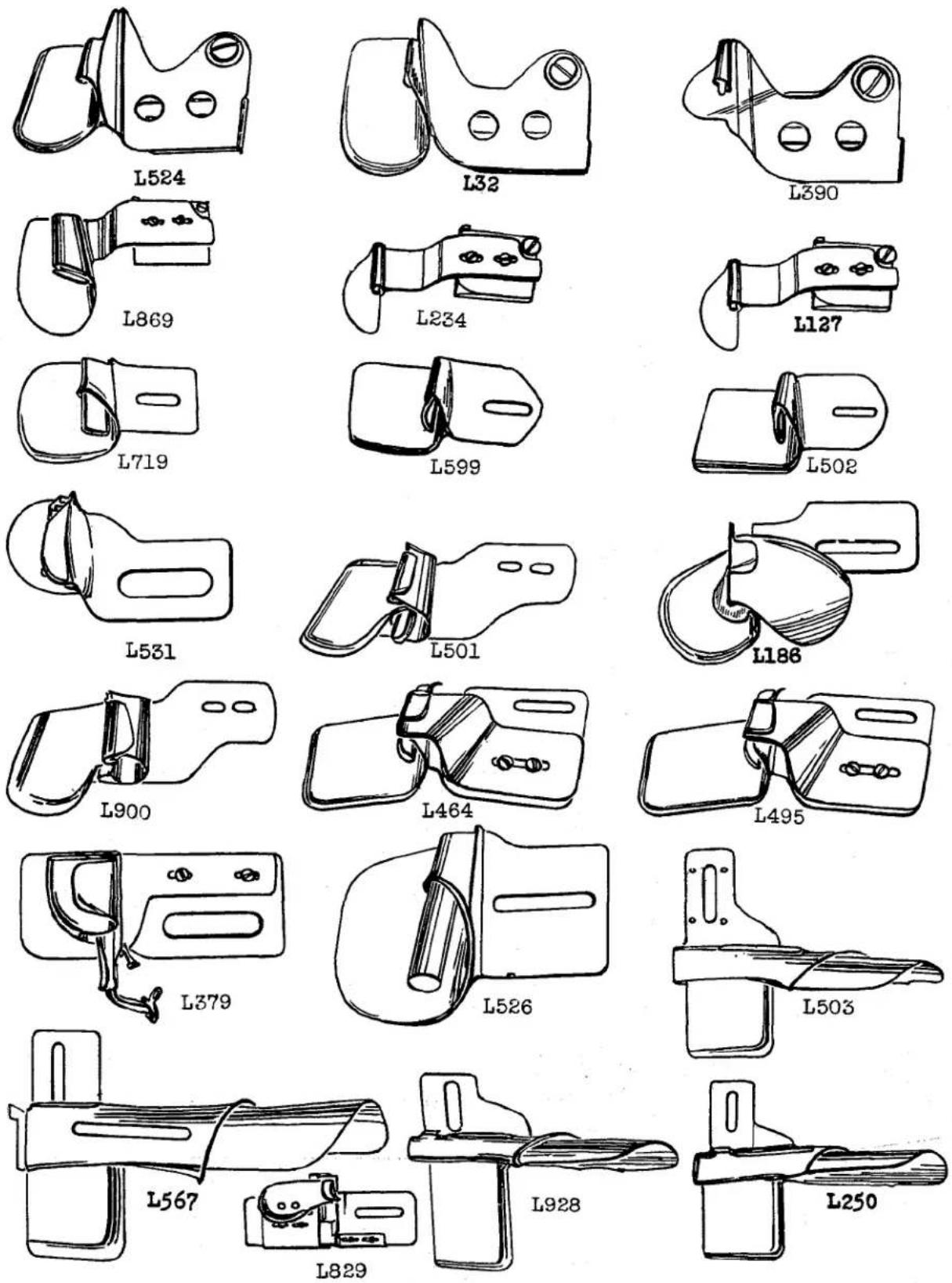
HEMMERS AND FOLDERS
| Part No. | Description |
| L32 | Hemming heavy work shirts, swing-out type, finishes 3/16 inch; feed dog No. 61205 A, throat plate No. 61224 C-063, presser foot No. 61220 (attaching screw No. 25 C, pivot screw No. 22726, washer No. 12957 E) |
| L127 | Hemming work shirts, 3/64 inch capacity, finishes 1/4 inch, swing-out type; feed dog No. 61205 C, throat plate No. 61224 C-063, presser foot No. 61420 AV (attaching screw No. 25 C, pivot screw No. 22760 A, scroll screw No. 22561) |
| L186 | Folder and Guide, capacity 3/64 inch, finishes 3/16 inch, lower ply turned upwardly, upper ply enters from right; feed dog No. 61205 A, throat plate No. 61224 C-063, presser foot No. 61220 Q (screw No. 25 C) |
| L234 | For hemming work shirts, swing-out type, finishes 5/16 inch; feed dog No. 61205 C, throat plate No. 61224 C-063, presser foot No. 61420 AV (attaching screw No. 25 C, scroll screw No. 22561, pivot screw No. 22760 A) |
| L250 | Folder, for attaching sleeve facings, light weight material, 1/32 inch capacity, 2-5/8 inch width of strip, finishes 1-1/8 inches, feed dog No. 61405 K, throat plate No. 61424 K, presser foot No. 61420 H (screw No. 25 C) |
| L379 | Folder, for cording and piping pajama coats, use 5/8 inch, bias cut tape and 3/32 inch cord; feed dog No. 61305 B, throat plate No. 61324 B-063, presser foot No. L380 (screw No. 25 C) |
| L390 | For hemming handkerchiefs, swing-out type, 3/64 inch capacity, finishes 3/32 inch; feed dog No. L369, throat plate No. L391, presser foot No. 61320 AJ (attaching screw No. 25 C) (pivot screw No. 22726, washer No. 12957 E) |
| L464 | Folder and Guide, making pants flies on heavy material, lower ply turned upwardly, top ply enters from right, 1/16 inch capacity; feed dog No. 61305 Q, throat plate No. 61324 Q-063, presser foot No. 61220 (attaching screw No. 22585 A, guide screw No. 22825) |
| L495 | Folder and Guide, making pants flies on medium weight materials, 1/32 inch capacity, lower ply turned upwardly, top ply enters from right; feed dog No. 61305 Q, throat plate No. 61324 Q-063, presser foot No. 61220 (attaching screw No. 22585 A, guide screw No. 22825) |
| L501 | Double Edge Folder, for joining shoulder seams on shirts, capacity 3/64 inch; feed dog No. 61205 C, throat plate No. 61224 C-063, presser foot No. L506 (screw No. 22585 A) |
| L502 | Hemming overall suspender straps, capacity 5/64 inch, finishes 5/16 inch, attached to swing-out bracket No. 23278 K; feed dog No. 61305 A, throat plate No. 61324 A-093, presser foot No. 61320 L (screw No. 22585 A) |
| L503 | Folder, for gabardine and light weight flannel sport shirts, 3/64 inch capacity, 2-5/8 inches width of strip, finishes 1-1/8 inches; feed dog No. 61405 K, throat plate No. 61424 K, presser foot No. 61420 H (screw No. 25 C) |
| L524 | For hemming shirts and similar garments, swing-out type, finishes 3/8 inch; feed dog No. 61205 D, throat plate No. 61224 F, presser foot No. L525 (attaching screw No. 25 C, pivot screw No. 22726, washer No. 12957 E) |
| L526 | Folder, for light weight army cloth, 1/32 inch capacity, finishes 11/16 inch; feed dog No. 61305 D, throat plate No. 61324 D-093, presser foot No. 61420 S (screw No. 25 C) |
| L531 | Double Edge Folder, for broadcloth, 1/32 inch capacity; feed dog No. 61205 A, throat plate No. 61224 C-063, presser foot No. 61220 (screw No. 25 C) |
| L567 | Folder, for attaching pajama cuffs, 5/16 inch margin to left of needle, 1/32 inch capacity, 5 inch width of strip, finishes 2-1/4 inches; feed dog No. 61405 K, throat plate No. 61424 K, presser foot No. L566 (screw No. 25 C) |
| L599 | Finishing button stays, work shirts, 5/64 inch capacity, finishes 3/16 inch hem, attached to swinging bracket No. 23278 K; feed dog No. 61205 A, throat plate No. 61224 C-063, presser foot No. 61320 AJ (screw No. 22585 A) |
| L719 | For hemming pajama pants, finishes 1-1/8 inches; feed dog No. 61205 A, throat plate No. 61224 C-063, presser foot No. 61220 (screw No. 25 C) |
| L829 | Folder, for attaching rick-rack to house dresses, 1/16 inch capacity, 1/4 inch fold; feed dog No. 61205 A, throat plate No. 61224 C-063, presser foot No. 61220 Q (screw No. 25 C) |
| L869 | For hemming herringbone twill, attached to swing-out bracket, finishes 5/8 inch; feed dog No. 61205 A, throat plate No. 61224 C-063, presser foot No. 61420 T (attaching screw No. 25 C, scroll screw No. 22561, pivot screw No. 22760 A) |
| L900 | For joining shoulder seams, has 5/16 inch underlap, 3/64 capacity; feed dog No. 61205 C, throat plate No. 61224 C-063, presser foot No. L506 (screw No. 22585 A) |
| L928 | Folder, for attaching 7/8 inch flannel sleeve facings, width of strips 2-1/4 inches, |
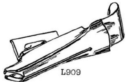
natural_image
Line drawing of a mechanical component labeled L909 (no other text or symbols)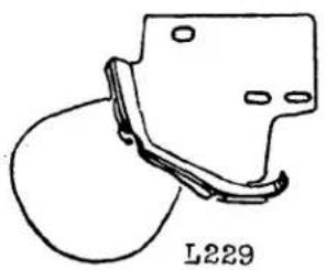
natural_image
Simple line drawing of a mechanical component with a curved handle and mounting holes (no text or symbols)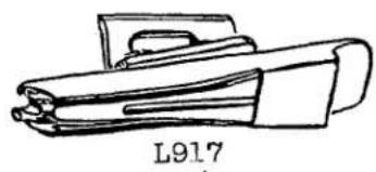
natural_image
Line drawing of a mechanical component labeled L917 (no other text or symbols)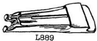
natural_image
Line drawing of a mechanical component labeled L889 (no other text or symbols)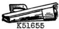

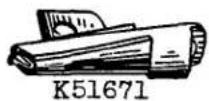

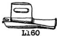
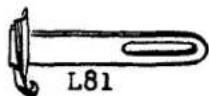
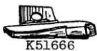


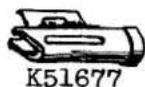


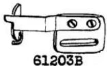
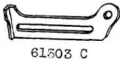

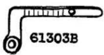
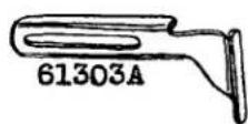
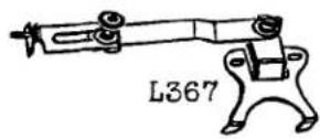
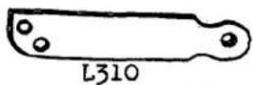
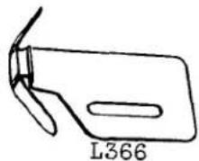
natural_image
Simple line drawing of a bird's head and wings (no text or symbols)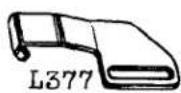

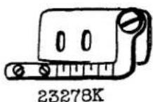
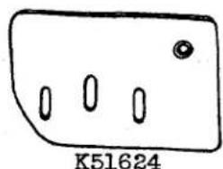
natural_image
Simple line drawing of a rectangular object with three oval cutouts and a small circular dot, labeled K51624 (no text or symbols on the object itself)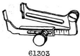
natural_image
Line drawing of a mechanical device with a circular component and a ring, labeled 61303 (no text or symbols on the device itself)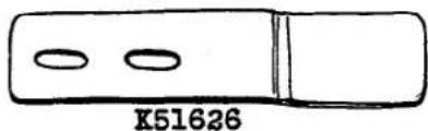
natural_image
Simple line drawing of a cylindrical object with two oval cutouts, labeled 'K51626' below (no other text or symbols)
BINDERS, GUIDES, MISCELLANEOUS PARTS
Part No.
| L18 |
| L67 |
| L77 |
| L81 |
| L89 |
| L125 |
| L160 |
| L184 |
| L212 |
| L229 |
| L289 |
| L310 |
| L366 |
| L367 |
| L377 |
| L766 |
| L889 |
| L909 |
| L917 |
| 23278 K |
| K51624 |
| K51626 |
| K51655 |
| K51666 |
| K51667 |
| K51671 |
| K51677 |
| K51699 |
| 61203 B |
| 61203 C |
| 61203 D |
| 61303 |
| 61303 A |
| 61303 B |
| 61303 C |
Description
| Cut Edge Binder, for 3/16 inch bias binding for heavy woolens; feed dog No. 61305 B, throat plate No. 61224 D-093, presser foot No. 61220 H (screw No. 22649 F-16) |
| Cut Edge Binder, for 1 inch bias binding for melton, 3/64 inch capacity; feed dog No. 61305 B, throat plate No. 61224 D-093, presser foot No. 61220 H (screw No. 22649 F-16) |
| Selvage Edge Binder, for 5/8 inch binding on mattress ticks, 3/64 inch capacity; feed dog No. 61305 B, throat plate No. 61224 D-093, presser foot No. 61220 H (screw No. 22649 F-16) |
| Selvage Edge Binder, for binding on mattress ticks; feed dog No. 61305 B, throat plate No. 61224 D-093, presser foot No. 61220 H (screw No. 22585 A) |
| Selvage Edge Binder, 5/32 inch jaw capacity; feed dog No. 61305 B, throat plate No. 61224 D-093, presser foot No. 61220 H (screw No. 22649 F-16) |
| Edge Guide, 7/8 inch guide surface (screw No. 22585 A) |
| Selvage Edge Binder, for 11/16 inch width ornamental binding on mattress ticks, 1/16 inch capacity; feed dog No. 61305 B, throat plate No. 61324 D-093, presser foot No. 61220 H (screw No. 22649 F-16) |
| Selvage Edge Binder, for light weight material, 1/32 inch capacity, finishes 1/2 inch; feed dog No. 61305 B, throat plate No. 61324 B-093, presser foot No. 61220 H (screw No. 22649 F-16) |
| Base, for swinging bracket No. K51659 (screw No. 94) |
| Cut Edge Binder, for pocket facings, 11/16 inch bias cut strip; feed dog No. 61305 B, throat plate No. 61324 B-093, presser foot No. 61220 H (screw No. 22649 F-16) |
| Selvage Edge Binder, for 11/16 inch binding; feed dog No. 61305 B, throat plate No. 61324 B-093, presser foot No. 61220 H (screw No. 22649 F-16) |
| Binder Swinging Arm Adapter Bracket, for special binders |
| Edge Guide, for stitching cuffs to shirts (screw No. 22585 A) |
| Adjustable Throw-out Edge Guide, for stitching down collars (attaching screw No. 94, pivot screw No. 22726, washer No. 12957 E, thumb nut No. T29, washer No. 21657 E) |
| Edge Guide, for use with plate hemmer No. L378 (screw No. 22585 A) |
| Selvage Edge Binder, for 9/16 inch binding, 5/32 inch jaw capacity; feed dog No. 61305 B, throat plate No. 61224 D-093, presser foot No. 61220 H (screw No. 22649 F-16) |
| Cut Edge Binder, for binding coat seams, 5/8 inch bias cut strips; feed dog No. 61205 B, throat plate No. 61224 B-093, presser foot No. L235 |
| Cut Edge Binder, for broadcloth shirts, 1/32 inch capacity, bias cut strips 1 1/8 inches, finishes 13/32 inch; feed dog No. 61305 B, throat plate No. 61224 D-063, presser foot No. 61220 H (screw No. 22649 F-16) |
| Cut Edge Binder, for silk and similar materials, 1/2 inch bias cut strips, 1/8 inch finish; feed dog No. L916, throat plate No. 61224 D-063, presser foot No. 61220 H (screw No. 22649 F-16) |
| Swing-out Bracket, for small plate hemmers (attaching screw No. 22585 A, pivot screw No. 22726, washer No. 35772 H) |
| Base, for Nos. K51606, K51623 (screw No. 94) |
| Hemmer Support, for No. K51606 (screw No. 22570, washer No. 20) |
| Cut Edge Binder, for 1 inch bias binding, 3/64 inch capacity; feed dog No. 61305 B, throat plate No. 61224 D-093, presser foot No. 61220 (screw No. 22649 F-16) |
| Cut Edge Binder, for 3/4 inch bias binding, 3/64 inch capacity; feed dog No. 61305 B, throat plate No. 61224 D-093, presser foot No. 61220 H (screw No. 22649 F-16) |
| Cut Edge Binder, for 7/8 inch bias binding; feed dog No. 61305 B, throat plate No. 61224 D-093, presser foot No. 61220 H (screw No. 22649 F-16) |
| Cut Edge Binder, for 1 inch bias binding, 1/16 inch capacity; feed dog No. 61305 B, throat plate No. 61224 D-093, presser foot No. 61220 H (screw No. 22649 F-16) |
| Selvage Edge Binder, for 5/8 inch bias binding, 1/32 inch capacity; feed dog No. 61305 B, throat plate No. 61224 D-093, presser foot No. 61220 H (screw No. 22649 F-16) |
| Cut Edge Binder, for 5/8 inch straight cut binding, 3/64 inch capacity; feed dog No. 61305 B, throat plate No. 61224 D-093, presser foot No. 61220 H (screw No. 22649 F-16) |
| Flexible Guide Assembly, for edge stitching collars and cuffs on dress shirts; one each Nos. 61203 C, 61203 D; two No. 22561 (screw No. 22585 A) |
| Flexible Edge Guide, for No. 61203 B (screw No. 22561) |
| Base, for No. 61203 B |
| Adjustable Edge Guide, swing-out type, for edge stitching coats and vests; one each Nos. 134, 22551, 61303 A, 61303 B, 61303 C, 61303 D (screw No. 22585 A) |
| Edge Guide, for No. 61303 (screw No. 22551) |
| Edge Guide Holder, for No. 61303, also for Nos. 23278 K, L378 |
| Edge Guide Holder Base, for No. 61303 |

natural_image
Simple line drawing of a mechanical component with three circular ports and a bracket (no text or symbols)K51623
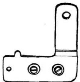
natural_image
Simple line drawing of a mechanical bracket or bracket with three circular holes (no text or symbols)K51625

natural_image
Simple line drawing of a mechanical device with three circular buttons and a handle (no text or symbols)K51606
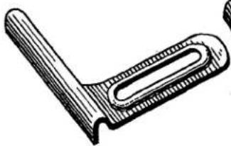
natural_image
Technical line drawing of a mechanical clamp or bracket (no text or symbols)61203

natural_image
Technical line drawing of a mechanical tool or bracket (no text or symbols)61203A
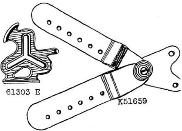

23133 F

natural_image
Technical line drawing of a mechanical component with gears and housing (no text or symbols)L628

natural_image
Technical line drawing of a mechanical gear assembly (no text or symbols)L629
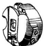
61413 E
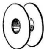
61212

21240 B

660-215

natural_image
Simple line drawing of a bent pipe or handle with no text or symbols
21240 F

natural_image
Technical line drawing of a mechanical clamp or tool with two curved arms and a central cylindrical component (no text or symbols)
21240 C
MISCELLANEOUS PARTS
| Part No. | Description |
| L628 | Rotating Hook Assembly, for sizes 16-4 to 30-4 thread |
| L629 | Bobbin Case Holder, for L628 |
| 660-215 | Retaining Ring, for No. 21240 C |
| 21240 A | Quilting Guide, with right or left guide (right guide No. 21240 D,left guide No. 21240 E, bracket No. 21204 B, bushing No.21204 C, spring No. 21240 F, retaining ring No. 660-215, screwNos. 91, T26) |
| 21240 B | Bracket, for No. 21240 A |
| 21240 C | Bushing, for No. 21240 A |
| 21240 D | Guide, right, for No. 21240 A |
| 21240 E | Guide, left, for No. 21240 A |
| 21240 F | Spring, for No. 21240 A |
| 23133 F | Welt Guide, for presser foot No. L86 A |
| K51606 | Swing-out Bracket, for plate hemmers with short bases; one eachNos. 12957 E, 22735, K51624, K51625, K51626; two each Nos.20, 22570 (screw No. 94) |
| K51623 | Swing-out Bracket, for plate hemmers with long bases; one eachNos. 12957 E, 22735, K51624, K51625, K51626; two each Nos.20, 22570 (screw No. 94) |
| K51625 | Swinging Arm, for Nos. K51606, K51623 (pivot screw No. 22735,washer No. 12957 E) |
| K51659 | Swing-out Bracket, for dual plate hemmers on sheets (screw No.94) |
| 61203 | Edge Guide, for machine with throat plates flush with bed (screwNo. 22551 A) |
| 61203 A | Edge Guide, for machine with raised throat plate (screw No.22551 A) |
| 61212 | Bobbin Spool |
| 61303 E | Three-Way Edge Guide (screw No. G26) |
| 61413 E | Bobbin Case Assembly, for L628 |

bar
| Item | Value | |---|---| | 22743 | 88 | | 730 | 730 | | 22733 | 22733 | | 22801 | 22801 | | 226 | 73A | | 187 | A | | 605 | 605 | | 22561 | 22561 | | 22825 | 22825 | | 22513 | T26 | | 23738 | 23738 | | 22547A | 22547A | | 22760A | 90 | | 22585 | 22585 | | 22570 | 22570 | | 22711 | 22711 | | 22726 | 134 | | 22735 | 94 | | 376 | 22649F-16 | | 22848 | 22848 | | 25C | 25C | | G26 | 22551A | | 22551 | 22551 | | 21745 E | 21745 E | | L97 | 197 | | 14076 | 14076 | | 22585A | 22585A | | 22775 | 22775 | | 22528 | 22528 | | 22818 | 91 |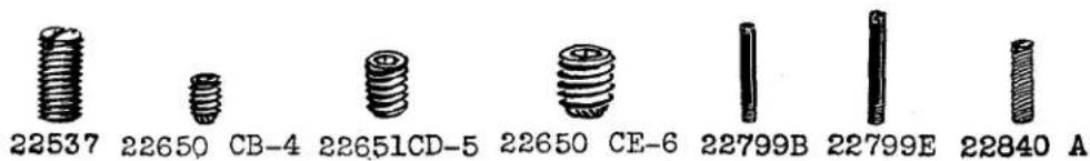
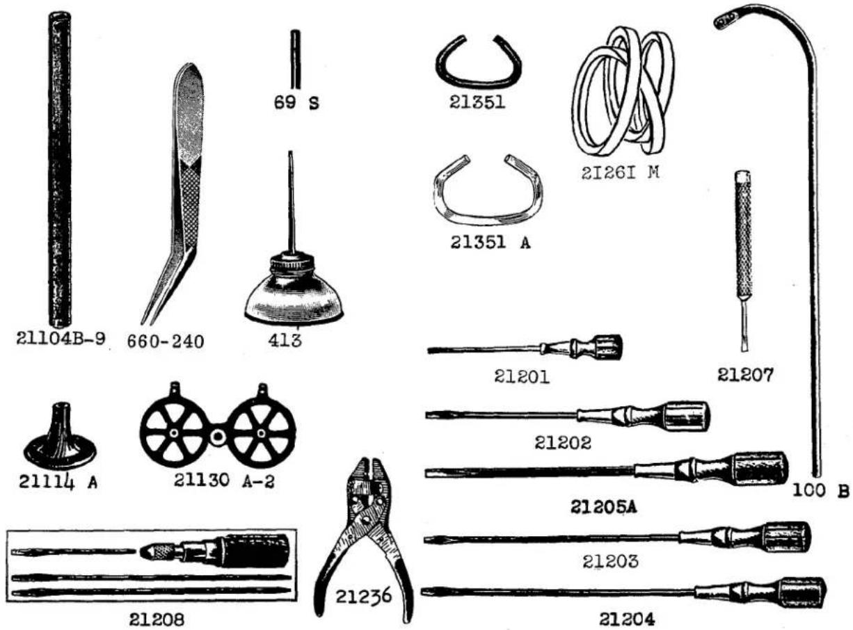
SCREWS AND MISCELLANEOUS PARTS
| Part No. | Description |
| 25 C | Screw, for attachment mounted on bed |
| G26 | Thumb Screw, for edge guide No. 61303 E |
| T26 | Screw, for spring No. 21240 F |
| 69 S | Spool Pin, 4 inches long |
| 73 A | Screw, for presser foot No. 61420 C |
| 73 C | Lock Screw, for set screw in shank No. 61430 D |
| 88 | Attaching Screw, for No. 61420 BA |
| 90 | Attaching Screw, for plate hemmer No. L385; also for Nos. L96, L378 |
| 91 | Screw, for No. 21240 C |
| 94 | Screw, for attachment No. L378; also for Nos. L122, L367 |
| L97 | Thumb Screw, for binders mounted on throat plate |
| 100 B | Thread Stand Wire |
| 134 | Pivot Screw, for edge guide Nos. 61303, L378 |
| 187 A | Screw, for knife and spring guide No. 1741 B; also for Nos. 61220 AC, 61320 E, 61320 F, 61320 U, 61420 L, L336, L637 |
| 226 | Screw, to hold spring No. L556; also for Nos. 22799 E, 35730 C, 35730 D, 35730 F |
| 376 | Screw, for throat plate |
| 413 | Oil Can |
| 605 | Screw, for presser foot guide No. L926 |
| 660-240 | Thread Tweezers |
| 14076 | Pivot Screw, for arm of No. 61420 BA |
| 21104 B-9 | Thread Stand Rod, 9 inches long; also in lengths from 2 inches to 48 inches |
| 21114 A | Thread Stand Base (two each No. 22651 CD-5) |
| 21130 A-2 | Thread Stand Seat (screw No. 22650 CE-6; two each No. 22650 CB-4) |
| 21201 | Screwdriver, 9/64 inch round blade, length over all 7 5/8 inches |
| 21202 | Screwdriver, 7/32 inch round blade, length over all 11 1/4 inches |
| 21203 | Screwdriver, 13/64 inch round blade, length over all 15 1/2 inches |
| 21204 | Screwdriver, 9/32 inch round blade, length over all 15 inches |
| 21205 A | Screwdriver, 3/8 inch round blade, length over all 14 inches |
| 21207 | Screwdriver, 7/64 inch round blade, length over all 2 1/2 inches |
| 21208 | Screwdriver Set, three detachable blades |
| 21236 | Belt Plier, for 3/8 inch and smaller round belting |
| 21261 M-410 | "V" Belt, No. 1 size, oil resistant, 41 inches outside circumference |
| 21261 M-420 | "V" Belt, 42 inches outside circumference |
| 21261 M-430 | "V" Belt, 43 inches outside circumference |
| 21261 M-440 | "V" Belt, 44 inches outside circumference |
| 21351 | Belt Hook, wire, for 9/32 inch round belt |
| 21351 A | Belt Hook, wire, for 3/8 inch round belt |
| 21745 E | Thumb Screw, for presser foot |
| 22513 | Screw, for folder No. L917 |
| 22528 | Screw, for feed dog holder |
| 22537 | Screw, for pulley |
| 22547 A | Screw, for adjustable spring guide on No. 61320 N |
| 22551 | Thumb Screw, for attachments mounted on bed Nos. 61303, L378 |
| 22551 A | Thumb Screw, for attachments mounted on bed No. 61203 |
| 22561 | Screw, for spring guide on presser foot No. 61429 K; also Nos. 61203 B, 61420 BA |
| 22570 | Attaching Screw, for plate hemmers used on swing-out brackets |
| 22585 | Screw, for locking lever on plate hemmer No. L95 |
| 22585 A | Screw, for edge guide No. 61303; also for Nos. 23278 K, 61203 B, L366, L377 |
| 22649 F-16 | Attaching Screw, for binders Nos. K1699, L766 |
| 22650 CB-4 | Screw, for thread stand wire |
| 22650 CE-6 | Screw, for thread stand seat |
| 22651 CD-5 | Screw, for thread stand base |
| 22711 | Screw, for attachments mounted on swinging bracket No. K51659 |
| 22726 | Pivot Screw, for No. L32; also for Nos. 23278 K, L367 |
| 22733 | Set Screw, for shank No. 61430 D |
| 22735 | Pivot Screw, for Nos. K51623, K51624 |
| 22738 | Screw, for hemmer scroll No. L727; also for Nos. 61220 AA, 61420 AC, L768 |
| 22743 | Screw, for locking spring No. 61420 BA |
| 22760 A | Screw, for Nos. L127, L869 |
| 22775 | Screw, for presser foot No. 61420 B |
| 22799 B | Hinge Screw, for No. 61420 BC; also for Nos. 61420 M, L454, L903, L926 |
| 22799 E | Hinge Screw, for No. L556 |
| 22801 | Hinge Screw, for No. L556; also for Nos. 35730 C, 35730 D, 35730 F |
| 22818 | Axle Screw, for roller No. 61420 BA |
| 22825 | Screw, for guide Nos. 464, 495 |
| 22840 A | Hinge Adjusting Screw, for presser foot No. L82; also for Nos. 61330 AH, 61420 AS, 61420 D, 61420 T, 61420 BT, 61420 BR |
| 22848 | Attaching Screw, rear, for swing-out guide No. 23278 K |
![INSTRUCTIONS FOR ASSEMBLING ACCESSORIES 29480 AJ OR 29480 CG & ISOLATORS 29480 AK ONTO TABLEBOARDS 2137INB,2137IND (ALL LENGTHS) POSITION BRACKETS AT STENCILED LINES [61376F] [61376E] [61376C] [61376B] [61376D] 61378 22846Q-16 [NA-15] 61374A (WIDE SLOT) NA-12 * 21393 T 21393 E [NA-12] G1374 G1376G [61376A] ASSEMBLY N° 61477 NA-12 NA-12A 666-166 21393 F TABLE BOARD 660-168 2137I NB-42,-48,-54,-60 2137I ND-42,-48,-54,-60 POSITION OIL PAN BY NAILING AT DIMPLES IN BOARD. PROPER POSITION PROVIDES DRAINING TO THE RIGHT FRONT CORNER NOTE: PART NUMBERS ENCLOSED IN BRACKETS ARE NOT IN- CLUDED WITH ACCESSORIES 29480AJ BUT ARE FUR- NISHED SEPARATELY AS 29480 AK. SC 329A 21662C 21665C 2166IP 69FD 21665 21661D 21663C 21664 ASSEMBLY N° 21660C PERIMETER OF BED MUST CONTACT THE TWO LEATHER ISOLATORS ONLY. IF BED CONTACTS BOARD, VIBRA- TION WILL BE TRANSMITTED END OF ISOLATORS MAY BE TRIMMED TO BRING CLOTH PLATE FLUSH WITH TABLE BOARD THE TWO NAILS SECURING LEATHER ISOLATOR TO TABLE BOARD MUST BE LOW ENOUGH TO CLEAR BED * 2/393 T INCLUDED WITH 29480 CG FOR 6/900 WITH PINKER](/content/2026/06/1210933/images/d154fbfd7f4ff83bfbd3485da99447cc3bec30aa3a6a6dcdc284260888dd833c.jpg)
ACCESSORIES FOR 61400 MACHINES
| PartNo. | Description | Amt.Req. |
| 29480 AJ | Accessories Assembly---- | 1 |
| NA12 | Nails, for drip pan---- | 4 |
| NA12 A | Nails, for felt pads---- | 4 |
| SC329 A | Wood Screws, for knee lifter hanger---- | 4 |
| 660-168 | Knee Pad, rubber---- | 1 |
| 666-166 | Oil Drain Jar, glass---- | 1 |
| 21393 E | Drip Pan---- | 1 |
| 21393 F | Oil Drain Clamp Spring---- | 1 |
| 21660 C | Knee Lifter Assembly---- | 1 |
| 21661 P | Knee Lifter Rock Shaft---- | 1 |
| 21661 D | Knee Lifter Rock Shaft Stop---- | 1 |
| 69 FD | Screw---- | 1 |
| 21662 C | Knee Lifter Hanger---- | 2 |
| 21663 C | Knee Lifter Plate Rod---- | 1 |
| 21664 | Knee Lifter Plate---- | 1 |
| 21665 | Knee Lifter Rock Shaft Connection---- | 2 |
| 69 FD | Screw---- | 2 |
| 21665 C | Knee Lifter Rock Shaft Connection Arm---- | 1 |
| 22846 Q-16 | Flat Head Wood Screws---- | 2 |
| 61374 | Hinge Plate---- | 1 |
| 61374 A | Hinge Plate, wide slot---- | 1 |
| 61376 G | Felt Pads---- | 4 |
| 61477 | Bobbin Winder Assembly---- | 1 |
| 61378 | Machine Rest Pin---- | 1 |
| ISOLATED MOUNTING PARTS FOR 61400 MACHINES | ||
| PartNo. | Description | Amt.Req. |
| 29480 AK | Isolated Mounting Parts Assembly---- | 1 |
| NA12 | Nails, for leather isolator pad---- | 2 |
| NA12 A | Nails, for felt pads---- | 2 |
| NA15 | Nails, for securing isolated bracket to table board---- | 12 |
| 61376 A | Leather Isolator Pad, rear---- | 1 |
| 61376 B | Leather Isolator Pad, front---- | 1 |
| 61376 C | Cork Isolator Pad, front---- | 1 |
| 61376 D | Isolator Bracket, front---- | 1 |
| 61376 E | Cork Isolator Pad, rear---- | 1 |
| 61376 F | Isolator Bracket, rear---- | 1 |
| 61376 G | Felt Pads---- | 2 |
| TABLE TOPS FOR 61400 MACHINES(Not Illustrated) | ||
| PartNo. | Description | Amt.Req. |
| 21371 NB-42 | Table Top, 42 x 20 x 1 3/4 inches, for isolated mounting on individualpower table with "Electro Drive"---- | 1 |
| 21371 NB-48 | Table Top, 48 inches long---- | 1 |
| 21371 NB-54 | Table Top, 54 inches long---- | 1 |
| 21371 NB-60 | Table Top, 60 inches long---- | 1 |
| 21371 ND-42 | Table Top, 42 x 16 x 1 3/4 inches, for isolated mounting on open lineshaft installation with transmitter No. 28636 Z---- | 1 |
| 21371 ND-48 | Table Top, 48 inches long---- | 1 |
| 21371 ND-54 | Table Top, 54 inches long---- | 1 |
| 21371 ND-60 | Table Top, 60 inches long---- | 1 |
| 21371 RU-42 | Table Top, 42 x 20 x 1 1/4 inches, for isolated mounting on E1400 pedestal---- | 1 |
| PEDESTAL ACCESSORIES FOR 61400 MACHINES(Not Illustrated) | ||
| PartNo. | Description | Amt.Req. |
| 29480 BU | Kit of Parts, to adapt machines to E1400 Pedestal---- | 1 |

The parts illustrated on the preceding page and described on this page represent the throat plate, feed dog, presser foot and pinking attachment used on Styles 61400 G or 61400 H
| Ref. No. | Part No. | Description | Amt. Req. |
| 1 | 24-142 | Throat Plate | 1 |
| 2 | 18-261 | Screw | 2 |
| 3 | 8-86 | Chip Guard | 1 |
| 4 | 23-167 | Feed Dog, 22 teeth per inch | 1 |
| 5 | 405-571 | Presser Foot | 1 |
| 6 | 21-269 | Spring | 1 |
| 7 | 61330 AC | Shank | 1 |
| 8 | 22-167 | Hinge Pin | 1 |
| 9 | 8-66 | Presser Foot Guard | 1 |
| 10 | 18-246 | Screw | 2 |
| 11 | 5-571 | Bottom | 1 |
| 17 | 27-164 | Pinker Driving Gear | 1 |
| 18 | 1025 L | Screw | 2 |
| 19 | 29480 BA | Pinking Attachment, complete | 1 |
| 20 | 27-68 | Driven Gear | 1 |
| 21 | 810 L | Screw | 2 |
| 22 | 32-81 | Cover, front | 1 |
| 23 | 18-355 | Screw | 4 |
| 24 | 32-82 | Cover, rear | 1 |
| 25 | 1025 L | Screw | 4 |
| 26 | 107-16 | Flange Driven Gear | 1 |
| 27 | 164-31 | Shim for 50-147 | 1 |
| 28 | CS331 | Screw | 2 |
| 29 | 1003 L | Screw | 2 |
| 30 | 50-147 | Bracket, for arm | 1 |
| 32 | 18-497 | Screw | 2 |
| 34 | 14-178 | Driven Gear Shaft | 1 |
| 35 | 18-1043 | Screw | 1 |
| 36 | 4124-32 | Ball Joint, upper | 1 |
| 37 | 1012 L | Nut, right hand thread | 1 |
| 38 | 71-52 | Connecting Rod | 1 |
| 39 | 869 L | Nut, left hand thread | 1 |
| 40 | 4124-33 | Ball Joint, lower | 1 |
| 41 | 40-57 | Washer | 1 |
| 42 | 1776 L | Screw | 2 |
| 43 | 46-108 | Link, for knife throw-out | 1 |
| 44 | 45-248 | Lever, for throw-out | 1 |
| 45 | 18-71 | Screw | 1 |
| 46 | 39536 AD | Spring Washer | 1 |
| 47 | 18-844 | Screw | 1 |
| 48 | 1160 L | Nut | 1 |
| 49 | 45-247 | Pinker Arm | 1 |
| 50 | 1003 L | Screw, for 14-171 | 1 |
| 51 | 76-18 | Handle, complete, for knife throw-out | 1 |
| 52 | 14-171 | Shaft, for base | 1 |
| 53 | CS231 | Nut, for 34-26 | 1 |
| 54 | 40-101 | Washer | 1 |
| 55 | 45-249 | Lever, for knife throw-out cam | 1 |
| 56 | CS331 | Screw, for 4124-33 | 1 |
| 57 | 34-26 | Cam Throw-out, for upper knife | 1 |
| 58 | 18-178 | Screw, for 14-172 | 1 |
| 59 | 14-172 | Shaft, for lever | 1 |
| 60 | 21-309 | Flat Spring | 2 |
| 61 | 99-134 | Holder, for upper knife | 1 |
| 62 | 18-558 | Screw, for lower knife | 2 |
| 63 | 119-25 | Upper Knife | 1 |
| 64 | 18-544 | Screw, for upper knife | 1 |
| 65 | 18-501 | Attaching Screw, for 29480 BA | 1 |
| 66 | 40-46 | Washer | 1 |
| 67 | 18-547 | Screw | 1 |
| 68 | 1012 L | Nut | 1 |
| 69 | 3-46 | Base | 1 |
| 70 | 119-24 | Lower Knife | 1 |
| 71 | 475-68 | Edge Guide | 1 |
| 72 | 18-422 | Screw | 1 |
| 73 | 18-353 | Screw | 1 |
| 74 | 40-86 | Washer | 1 |
| 75 | 99-143 | Edge Guide Holder | 1 |
| 76 | 99-329 | Holder | 1 |
| 77 | 21210 A | Washer | 1 |
| 78 | 810 L | Screw | 1 |
NUMERICAL INDEX OF PARTS
| Part No. | Page No. | Part No. | Page No. | Part No. | Page No. | Part No. | Page No. |
| L3 | 69 | L119 | 37 | L394 | 67 | 666-20 | 27 |
| L11 | 69 | L122 | 69 | L397 | 43 | 666-104 | 27 |
| NA12 | 79 | L122 A | 63 | L398 | 43 | 666-126 | 27 |
| NA12 A | 79 | L123 | 69 | L404 | 61 | 666-127 | 27 |
| NA15 | 79 | L125 | 73 | L405 | 59 | 666-166 | 79 |
| L17 | 51 | L127 | 71 | L408 | 53 | 666-186 | 29 |
| L17 A | 65 | 134 | 77 | L412 | 55 | L683 | 63 |
| 18 | 35 | L139 | 59 | 413 | 77 | L688 | 69 |
| L18 | 73 | L143 | 37 | L415 | 57 | 719 | 31 |
| 20 | 63 | L154 | 69 | L429 | 49 | L719 | 71 |
| CL21 | 29 | L158 | 55 | L433 | 69 | L727 | 59 |
| 25 C | 77 | L160 | 73 | L435 | 43 | L743 | 59 |
| G26 | 77 | 161 | 31 | L436 | 43 | L748 | 53 |
| T26 | 77 | L175 | 61 | L437 | 43 | L756 | 59 |
| 28 C | 35 | L179 | 67 | L438 | 43 | L763 | 69 |
| L28 | 37 | L180 | 67 | L440 | 55 | L766 | 73 |
| L29 | 37 | L184 | 73 | L464 | 71 | L768 | 49 |
| T29 | 63 | L186 | 71 | L471 | 69 | L769 | 49 |
| L30 | 59 | 187 A | 77 | L473 | 59 | L774 | 63 |
| L32 | 71 | L189 | 49 | L489 | 69 | L775 | 59 |
| L33 A | 41 | L193 | 49 | L495 | 71 | L829 | 71 |
| L39 A | 65 | L195 | 51 | L501 | 71 | L836 | 59 |
| 50-552 Blk | 31 | L196 | 67 | L502 | 71 | L868 | 59 |
| 50-558 Blk | 27 | L205 | 49 | L503 | 71 | L869 | 71 |
| 50-567 Blk | 33 | L206 | 37 | L505 | 55 | L875 | 57 |
| 50-568 Blk | 27 | L212 | 73 | L506 | 49 | L889 | 73 |
| 50-799 Blk | 35 | L217 | 49 | L516 | 67 | L900 | 71 |
| L54 | 37 | L218 | 51 | L518 | 49 | L903 | 57 |
| L55 | 37 | L220 | 55 | L519 | 37 | L909 | 73 |
| HA61 D | 31 | L222 | 37 | L520 | 37 | L916 | 41 |
| L64 | 53 | L223 | 37 | L524 | 71 | L917 | 73 |
| L67 | 73 | 226 | 77 | L525 | 57 | L925 | 65 |
| L69 | 53 | L229 | 73 | L526 | 71 | L926 | 65 |
| 69 S | 77 | L234 | 71 | L529 | 53 | L928 | 71 |
| 69 FD | 79 | L235 | 57 | 531 | 31 | L936 | 37 |
| L72 | 53 | L237 | 57 | L531 | 71 | L943 | 57 |
| 73 A | 77 | L250 | 71 | L546 | 51 | L955 | 65 |
| 73 C | 77 | L265 | 69 | L549 | 43 | L960 | 57 |
| 77 | 29 | L266 | 51 | L550 | 43 | 1230 B | 63 |
| L77 | 73 | L287 | 37 | L556 | 57 | 1580 G | 63 |
| L81 | 73 | L289 | 73 | L563 | 57 | 1741 A | 63 |
| L82 A | 51 | L290 | 49 | L564 | 67 | 1741 B | 63 |
| L83 A | 43 | L292 | 59 | L566 | 57 | 2339 F | 35 |
| L86 A | 55 | L293 | 55 | L567 | 71 | 3346 A | 63 |
| 88 | 31, 33, 35, 77 | L298 | 49 | L579 | 37 | 6990 | 63 |
| L302 | 67 | L580 | 37 | 8372 A | 29 | ||
| 88 D | 31 | L310 | 73 | L582 | 59 | 9937 | 29, 3 |
| 89 | 27, 31, 33, 35 | L313 | 53 | L599 | 71 | 12957 E | 63 |
| L326 | 53 | 605 | 77 | 12987 A | 35 | ||
| L89 | 73 | L327 | 67 | L610 | 69 | 14076 | 77 |
| 90 | 31, 77 | SC329 A | 79 | L627 | 69 | 15037 A | 31 |
| 91 | 77 | L336 | 57 | L628 | 33, 75 | 15872 F | 29 |
| 91 A | 27 | L355 | 67 | L629 | 33, 75 | 21104 B | 77 |
| 93 | 27 | L364 | 67 | L631 | 67 | 21114 A | 77 |
| 93 A | 29, 31 | L366 | 73 | L637 | 57 | 21130 A | 77 |
| 94 | 77 | L367 | 73 | 652 B-20 | 29 | 21201 | 77 |
| 95 | 31, 35 | L368 | 49 | L653 | 57 | 21202 | 77 |
| L95 | 53 | L369 | 37 | L659 | 41 | 21203 | 77 |
| 96 | 29, 31, 35 | 376 | 27, 35, 77 | 660-142 | 29 | 21204 | 77 |
| 96 A | 27 | L377 | 73 | 660-168 | 79 | 21205 A | 77 |
| L96 | 67 | L378 | 67 | 660-205 | 29 | 21207 | 77 |
| L97 | 77 | L379 | 71 | 660-215 | 75 | 21208 | 77 |
| 98 | 35 | L380 | 57 | 660-225 | 31 | 21236 | 77 |
| 100 B | 77 | L385 | 67 | 660-226 | 35 | 21240 A | 75 |
| 109 | 27 | L390 | 71 | 660-240 | 77 | 21240 B | 75 |
| L118 | 37 | L391 | 37 | 660-257 | 27 | 21240 C | 75 |
NUMERICAL INDEX OF PARTS
| Part No. | Page No. | Part No. | Page No. | Part No. | Page No. | Part No. | Page No. |
| 21240 D | 75 | 22747 B | 35 | 51239 AC | 35 | 61220 N | 51 |
| 21240 E | 75 | 22757 C | 29 | 51239 AE | 35 | 61220 P | 53 |
| 21240 F | 75 | 22758 B | 29 | 51242 M | 31 | 61220 Q | 55 |
| 21261 M | 77 | 22760 A | 77 | 51430 F | 63 | 61220 R | 51 |
| 21351 | 77 | 22764 B | 31 | K51606 | 75 | 61220 S | 55 |
| 21351 A | 77 | 22768 | 31 | K51619 | 67 | 61220 T | 49 |
| 21393 E | 79 | 22768 A | 29 | K51621 | 67 | 61220 V | 49 |
| 21393 F | 79 | 22775 | 29, 35, 77 | K51622 | 69 | 61220 W | 55 |
| 21657 E | 35, 63 | 22775 A | 31 | K51623 | 75 | 61220 AA | 59 |
| 21660 C | 79 | 22799 B | 77 | K51624 | 73 | 61220 AB | 49 |
| 21661 D | 79 | 22799 E | 77 | K51625 | 75 | 61220 AC | 57 |
| 21661 P | 79 | 22799 M | 29 | K51626 | 73 | 61224 | 37 |
| 21662 C | 79 | 22801 | 77 | K51645 | 57 | 61224 B | 41 |
| 21663 C | 79 | 22802 A | 31 | K51649 | 69 | 61224 C | 41, 47 |
| 21664 | 79 | 22817 A | 29 | K51650 | 69 | 61224 D | 41 |
| 21665 | 79 | 22818 | 77 | K51655 | 73 | 61224 E | 39 |
| 21665 C | 79 | 22825 | 77 | K51659 | 75 | 61224 F | 39 |
| 21745 E | 77 | 22832 G | 35 | K51666 | 73 | 61230 | 63 |
| 22513 | 77 | 22840 A | 77 | K51667 | 73 | 61230 A | 63 |
| 22528 | 31, 77 | 22845 D | 31 | K51668 | 69 | 61230 B | 63 |
| 22537 | 77 | 22845 G | 31 | K51669 | 69 | 61230 C | 63 |
| 22539 D | 27 | 22846 Q-16 | 79 | K51670 | 67 | 61230 J | 63 |
| 22547 A | 77 | 22848 | 77 | K51671 | 73 | 61230 L | 61 |
| 22551 | 77 | 22863 B | 27 | K51672 | 69 | 61230 M | 61 |
| 22551 A | 77 | 22874 | 35 | K51677 | 73 | 61230 S | 63 |
| 22560 A | 35 | 22874 F | 29 | K51681 | 67 | 61230 U | 63 |
| 22560 B | 29, 35 | 22880 | 29, 31 | K51683 | 49 | 61230 V | 61 |
| 22561 | 77 | 22882 | 35 | K51684 | 57 | 61230 W | 61 |
| 22562 B | 29 | 22884 | 29, 31 | K51687 | 51 | 61230 X | 63 |
| 22564 B | 31, 35 | 22890 | 29 | K51688 | 67 | 61230 AK | 63 |
| 22564 E | 33 | 22891 | 35 | K51689 | 67 | 61231 | 63 |
| 22564 F | 33 | 22892 | 29 | K51699 | 73 | 61231 A | 63 |
| 22565 C | 35 | 22894 E | 31 | 51930 | 63 | 61233 N | 31 |
| 22569 B | 27 | 22894 J | 31 | 52930 T | 63 | 61235 | 31 |
| 22569 C | 33 | 22894 T | 35 | 53678 N | 35 | 61236 | 31 |
| 22569 H | 33 | 22894 V | 29 | 61149 | 35 | 61236 G | 31 |
| 22570 | 77 | 22894 AB | 29 | 61149 G | 35 | 61242 | 33 |
| 22570 A | 27 | 23133 F | 75 | 61149 H | 35 | 61244 | 33 |
| 22570 B | 29 | 23278 K | 73 | 61202 | 27 | 61245 G | 27 |
| 22574 | 29 | 23510 | 67 | 61203 | 75 | 61246 A | 31 |
| 22580 | 35 | 28618 | 63 | 61203 A | 75 | 61248 H | 31 |
| 22585 | 77 | 29126 BS | 31 | 61203 B | 73 | 61251 D | 29 |
| 22585 A | 27, 77 | 29126 DG | 35 | 61203 C | 73 | 61252 J | 29 |
| 22596 D | 29 | 29474 G | 33 | 61203 D | 73 | 61255 | 29 |
| 22597 A | 27, 29 | 29480 AJ | 79 | 61205 | 37 | 61255 H | 29 |
| 22597 B | 35 | 29480 AK | 79 | 61205 A | 41, 47 | 61256 | 29, 35 |
| 22597 E | 27 | 29486 B | 29 | 61205 B | 41 | 61256 G | 29 |
| 22649 F-16 | 77 | 35730 C | 61 | 61205 C | 41, 47 | 61260 A | 31 |
| 22650 CB-4 | 77 | 35730 D | 61 | 61205 D | 39 | 61261 A | 31 |
| 22650 CE-6 | 77 | 35772 H | 63 | 61205 E | 39 | 61263 | 31 |
| 22651 CD-5 | 77 | 41258 | 35 | 61205 CA | 41 | 61264 | 31 |
| 22704 | 35 | 41358 M | 35 | 61208 B | 33 | 61264 A | 31 |
| 22711 | 77 | 41358 N | 35 | 61210 B | 33 | 61265 | 29 |
| 22712 F | 29 | 41358 P | 35 | 61212 | 33, 75 | 61267 | 29 |
| 22716 A | 33 | 41358 Q | 35 | 61216 | 33 | 61267 G | 29 |
| 22716 B | 33 | 41358 S | 35 | 61216 N | 33 | 61271 | 27 |
| 22716 H | 33 | 41358 T | 35 | 61220 | 55 | 61272 | 27 |
| 22726 | 77 | 43443 Q | 35 | 61220 B | 59 | 61273 | 27 |
| 22729 | 35 | 51239 B | 35 | 61220 C | 61 | 61282 A | 27 |
| 22730 | 27 | 51239 E | 35 | 61220 D | 59 | 61282 D | 27 |
| 22733 | 77 | 51239 G | 35 | 61220 G | 51 | 61282 E | 27 |
| 22735 | 77 | 51239 S | 35 | 61220 H | 51 | 61292 C | 27 |
| 22738 | 77 | 51239 T | 35 | 61220 J | 51 | 61292 G | 27 |
| 22742 | 27 | 51239 U | 35 | 61220 K | 55 | 61292 H | 27 |
| 22743 | 31, 77 | 51239 AA | 35 | 61220 L | 59 | 61293 | 27 |
| 22747 | 35 | 51239 AB | 35 | 61220 M | 59 | 61293 N | 27 |
NUMERICAL INDEX OF PARTS
| Part No. | Page No. | Part No. | Page No. | Part No. | Page No. | Part No. | Page No. |
| 61303 | 73 | 61324 U | 43 | 61376 A | 79 | 61420 B | 55 |
| 61303 A | 73 | 61330 | 63 | 61376 B | 79 | 61420 C | 51 |
| 61303 B | 73 | 61330 B | 63 | 61376 C | 79 | 61420 E | 49 |
| 61303 C | 73 | 61330 C | 61 | 61376 D | 79 | 61420 F | 49 |
| 61303 D | 63 | 61330 E | 63 | 61376 E | 79 | 61420 H | 55 |
| 61303 E | 75 | 61330 F | 63 | 61376 F | 79 | 61420 J | 65 |
| 61305 | 39 | 61330 L | 61 | 61376 G | 79 | 61420 K | 57 |
| 61305 A | 45, 47 | 61330 M | 61 | 61378 | 79 | 61420 L | 57 |
| 61305 B | 41 | 61330 N | 63 | B61382 H | 27 | 61420 M | 55 |
| 61305 C | 43 | 61330 P | 63 | 61382 J | 27 | 61420 N | 49 |
| 61305 D | 41 | 61330 Q | 63 | 61391 C | 29 | 61420 P | 51 |
| 61305 E | 39 | 61330 R | 61 | 61391 D | 29 | 61420 R | 51 |
| 61305 F | 41 | 61330 T | 61 | 61392 F-9 | 27 | 61420 S | 49 |
| 61305 G | 37, 39 | 61330 V | 61 | 61392 F-14 | 27 | 61420 T | 55 |
| 61305 K | 43, 47 | 61330 W | 61 | 61393 B | 27 | 61420 U | 49 |
| 61305 M | 39 | 61330 X | 63 | 61393 C | 27 | 61420 V | 49 |
| 61305 N | 43 | 61330 Y | 61 | 61393 E | 27 | 61420 W | 59 |
| 61305 P | 39 | 61330 Z | 61 | 61394 L | 33 | 61420 X | 59 |
| 61305 Q | 43 | 61330 AA | 61 | 61394 M | 33 | 61420 Y | 59 |
| 61305 S | 41 | 61330 AB | 61 | 61394 P | 27 | 61420 Z | 59 |
| 61305 T | 45, 47 | 61330 AC | 63 | 61394 Q | 27 | 61420 AA | 65 |
| 61305 U | 43 | 61330 AD | 61 | 61394 R | 27 | 61420 AB | 65 |
| 61320 | 49 | 61330 AE | 61 | 61394 Z | 33 | 61420 AC | 59 |
| 61320 B | 51 | 61330 AF | 61 | 61394 AA | 33 | 61420 AD | 53 |
| 61320 C | 55 | 61330 AG | 61 | 61394 AC | 33 | 61420 AE | 53 |
| 61320 E | 57 | 61330 AH | 63 | 61394 AE | 27 | 61420 AF | 53 |
| 61320 F | 57 | 61330 AJ | 61 | 61394 AF | 33 | 61420 AG | 51 |
| 61320 K | 49 | 61330 AK | 63 | 61394 AJ | 33 | 61420 AH | 49 |
| 61320 L | 53 | 61330 AL | 61 | 61396 F | 33 | 61420 AJ | 49 |
| 61320 M | 51 | 61330 AM | 61 | 61405 A | 47 | 61420 AK | 51 |
| 61320 N | 57 | 61330 AN | 61 | 61405 B | 47 | 61420 AL | 51 |
| 61320 P | 51 | 61330 AP | 63 | 61405 C | 45 | 61420 AM | 51 |
| 61320 Q | 53 | 61330 AR | 61 | 61405 E | 47 | 61420 AN | 55 |
| 61320 R | 51 | 61330 AS | 61 | 61405 F | 47 | 61420 AP | 55 |
| 61320 S | 53 | 61330 AU | 61 | 61405 G | 45, 47 | 61420 AR | 55 |
| 61320 U | 57 | 61330 AV | 63 | 61405 H | 45 | 61420 AS | 55 |
| 61320 V | 57 | 61330 AW | 61 | 61405 J | 39 | 61420 AT | 55 |
| 61320 X | 65 | 61330 AX | 61 | 61405 K | 45 | 61420 AU | 57 |
| 61320 Z | 53 | 61336 U | 31 | 61405 L | 39 | 61420 AV | 51 |
| 61320 AA | 53 | 61336 Y | 31 | 61405 M | 39 | 61420 AW | 51 |
| 61320 AB | 51 | 61339 D | 35 | 61405 N | 45 | 61420 AX | 53 |
| 61320 AC | 49 | 61339 E | 35 | 61405 P | 39 | 61420 AY | 53 |
| 61320 AD | 53 | 61339 F | 35 | 61405 R | 39 | 61420 AZ | 53 |
| 61320 AE | 57 | 61339 H | 35 | 61405 S | 45, 47 | 61420 BA | 53 |
| 61320 AF | 51 | 61339 S | 35 | 61405 T | 45 | 61420 BB | 57 |
| 61320 AG | 55 | 61340 C | 33 | 61405 U | 39 | 61420 BC | 55 |
| 61320 AH | 55 | 61341 C | 27 | 61405 V | 37 | 61420 BD | 57 |
| 61320 AJ | 55 | 61341 D | 27 | 61405 X | 41 | 61420 BE | 49 |
| 61320 AL | 65 | 61341 G | 33 | 61405 Y | 37 | 61420 BG | 49 |
| 61320 AM | 65 | 61341 J | 33 | 61405 Z | 41 | 61420 BH | 51 |
| 61321 J | 29 | 61348 A | 31 | 61407 B | 33 | 61420 BJ | 51 |
| 61321 L | 29 | 61351 C | 29 | 61407 C | 33 | 61420 BK | 65 |
| 61322 B | 29 | 61351 J | 27 | 61411 A | 33 | 61420 BN | 55 |
| 61324 | 39 | 61351 K | 29 | 61413 B | 75 | 61420 BR | 55 |
| 61324 A | 45, 47 | 61351 Q | 29 | 61413 E | 33, 75 | 61420 BT | 57 |
| 61324 B | 41 | 61356 | 29 | 61413 F | 33 | 61421 | 29 |
| 61324 C | 43 | 61360 | 29 | 61413 G | 33 | 61421 A | 29 |
| 61324 D | 41 | 61360 G | 31 | 61414 | 33 | 61424 A | 47 |
| 61324 E | 39 | 61366 C | 29 | 61414 A | 27 | 61424 B | 47 |
| 61324 F | 39 | 61368 | 29 | 61414 C | 33 | 61424 C | 45 |
| 61324 J | 43, 47 | 61368 A | 29 | 61415 | 33 | 61424 E | 47 |
| 61324 L | 39 | 61368 E | 29 | 61415 A | 33 | 61424 F | 47 |
| 61324 N | 43 | 61368 F | 29 | 61417 | 29 | 61424 G | 45, 47 |
| 61324 P | 39 | 61374 | 79 | 61417 C | 35 | 61424 H | 45 |
| 61324 Q | 43 | 61374 A | 79 | 61420 | 55 | 61424 J | 39 |
| 61324 R | 45, 47 | 61375 | 27 | 61420 A | 55 | 61424 K | 45 |
NUMERICAL INDEX OF PARTS
| Part No. | Page No. | Part No. | Page No. | Part No. | Page No. | Part No. | Page No. |
| 61424 L | 39 | 61434 G | 31 | 61439 AJ | 35 | 61457 C | 27 |
| 61424 M | 39 | 61437 A | 31, 35 | 61439 AV | 35 | 61457 E | 35 |
| 61424 N | 45 | 61437 B | 31 | 61443 | 31 | 61457 F | 35 |
| 61424 P | 39 | 61437 C | 31, 35 | 61445 | 31 | 61457 G | 35 |
| 61424 R | 39 | 61437 U | 35 | 61447 | 31 | 61458 | 29 |
| 61424 S | 45, 47 | 61438 A | 31 | 61449 | 31 | 61458 A | 29 |
| 61424 T | 45 | 61439 | 31 | 61449 A | 31 | 61459 A | 29 |
| 61424 U | 39 | 61439 A | 31 | 61449 B | 31, 35 | 61459 B | 29 |
| 61424 X | 41 | 61439 F | 35 | 61449 E | 31 | 61466 A | 29 |
| 61424 Y | 37 | 61439 G | 35 | 61449 F | 31 | 61468 | 29 |
| 61430 A | 63 | 61439 H | 35 | 61449 G | 31 | 61470 | 27 |
| 61430 B | 63 | 61439 K | 35 | 61449 H | 27 | 61470 B | 27 |
| 61430 C | 61 | 61439 M | 35 | 61449 L | 35 | 61477 | 79 |
| 61430 L | 63 | 61439 N | 65 | 61449 AA | 35 | 61490 | 27 |
| 61430 M | 63 | 61439 P | 35 | 61453 | 27 | 61490 A | 27 |
| 61430 N | 63 | 61439 R | 35 | 61453 B | 29 | 61492 | 27 |
| 61430 P | 63 | 61439 S | 65 | 61454 | 27 | 61492 A | 27 |
| 61432 A | 31 | 61439 T | 35, 65 | 61454 A | 29 | 61494 | 33 |
| 61432 B | 27 | 61439 U | 65 | 61454 B | 29 | 61494 A | 33 |
| 61432 C | 27 | 61439 V | 65 | 61454 D | 29 | 61494 B | 33 |
| 61432 D | 27 | 61439 W | 65 | 61457 | 29 | 61494 U | 33 |
| 61432 E | 27 | 61439 X | 65 | 61457 B | 29 | 62262 | 31 |
| 61434 | 31 |

natural_image
World map projection with latitude and longitude grid lines (no text or labels)WORLDWIDE SALES AND SERVICE
Union Special Corporation maintains sales and service facilities throughout the world. These offices will aid you in the selection of the right sewing equipment for your particular operation. Union Special Corporation representatives and service technicians are factory trained and are able to serve your needs promptly and efficiently. Whatever your location, there is a qualified representative to serve you.
Corporate
Office:
One Union Special Plaza
Huntley, IL 60142
Phone: 847·669·5101
Fax: 847·669·4454
European Distribution Center:
Union Special GmbH
Raiffeisenstrasse 3
D-71696 Möglingen, Germany
Tel: 49·07141·247·0
Fax: 49·7141·247·100
Brussels, Belgium
Charlotte, N.C.
El Paso, TX
Hong Kong, China
Huntley, IL
Leicester, England
Lille, France
Miami, FL
Milan, Italy
Möglingen, Germany
Montreal, Quebec
Osaka, Japan
Santa Fe Springs, CA
Other Representatives throughout all parts of the world.

Finest Quality
Union Special® INDUSTRIAL SEWING EQUIPMENT
- Union Special INDUSTRIAL SEWING EQUIPMENT
- Aid Plant Layout! Boost Production!
- PEDESTAL MOUNTED MACHINES
- LIST OF PARTS AND INSTRUCTIONS
- Styles
- FOREWORD
- APPLICATION OF CATALOG
- IDENTIFICATION OF MACHINE
- ILLUSTRATIONS OF STANDARD LOCKSTITCH MACHINES
- INSTALLING
- ASSEMBLY PARTS
- STANDARD ACCESSORIES
- TABLE TOPS
- KNEE PRESS
- DRIP PAN
- BOBBIN WINDER
- BELTS
- LUBRICATION
- CAUTION!!
- RECOMMENDED OILS
- NEEDLES
- TYPE NUMBERS AND SIZES
- SELECTING THE SIZE OF THE NEEDLE
- OPERATOR'S INSTRUCTIONS
- THREAD
- SELECTING THE HOOK ASSEMBLY
- REMOVING THE BOBBIN CASE
- WINDING THE BOBBIN
- WINDING THE BOBBIN (Continued)
- THREADING THE BOBBIN CASE
- REPLACING THE BOBBIN CASE
- INSERTING THE NEEDLE
- THREADING THE NEEDLE
- PREPARATION FOR SEWING
- TENSIONS
- BOBBIN THREAD TENSION
- NEEDLE THREAD TENSION
- TO CHANGE THE STITCH LENGTH
- PRESSURE ON MATERIAL
- SETTING THE NEEDLE BAR TO HEIGHT
- TIMING THE HOOK
- HOOK LUBRICATION
- HOOK SHAFT
- FEED DOG HEIGHT
- PRESSER BAR CONNECTION
- PRESSER BAR GUIDE
- THREAD CONTROL
- LOCATING TENSION RELEASE MECHANISM
- STITCH REGULATING PLUNGER LOCK
- FEED TIMING
- FEED TIMING (Continued)
- MACHINE TIMING
- MECHANIC'S INSTRUCTIONS
- FOR
- TOP ROLLER FEED MACHINES
- STYLES 61400 N, 61400 P, 61400 R, 61400 S
- (Continued)
- USEFUL SUGGESTIONS
- ORDERING REPAIR PARTS
- ILLUSTRATIONS
- IDENTIFYING PARTS
- USE GENUINE NEEDLES AND REPAIR PARTS
- TERMS
- PRESSER FEET
- HEMMERS
- Part No.
- Description
- BINDERS, GUIDES, MISCELLANEOUS PARTS
- WORLDWIDE SALES AND SERVICE
Marke : Union Special
Modell : 61400S
Kategorie : Industrienähmaschine