
NV-D80EV - Videorekorder PANASONIC - Kostenlose Bedienungsanleitung
Finden Sie kostenlos die Bedienungsanleitung des Geräts NV-D80EV PANASONIC als PDF.

| Produkttyp | VHS-Videorekorder |
| Modell | NV-D80EV |
| Marke | Panasonic |
| Abmessungen (B x H x T) | ca. 430 x 88 x 350 mm |
| Gewicht | ca. 4,5 kg |
| Stromversorgung | 220–240 V, 50 Hz |
| Leistungsaufnahme | ca. 20 W |
| Bandsystem | VHS |
| Wiedergabesystem | PAL |
| Längste Aufnahmezeit | 240 Min. (LP) / 480 Min. (EP) |
| Timeraufnahme | Ja (bis zu 8 Programme) |
| Anschlüsse | HF-Eingang (Antenne), HF-Ausgang, SCART, Cinch (Audio/Video) |
| Funktionen | Wiedergabe, Aufnahme, Timeraufnahme, Bildsuchlauf, Standbild |
| Kopfreinigung | Automatische Reinigungsfunktion |
| Reinigung | Gehäuse mit trockenem Tuch reinigen; keine Flüssigkeiten verwenden |
| Wartung | Regelmäßige Reinigung der Videoköpfe mit spezieller Reinigungskassette |
| Sicherheitshinweis | Netzstecker ziehen vor Reinigung; nicht öffnen |
| Ersatzteile | Fernbedienung, Netzteil, Videoköpfe (beim Fachhändler erhältlich) |
| Reparierbarkeit | Durch qualifiziertes Fachpersonal; Ersatzteile verfügbar |
| Lieferumfang | Videorekorder, Fernbedienung, Netzleitung, Bedienungsanleitung |
Häufig gestellte Fragen - NV-D80EV PANASONIC
Benutzerfragen zu NV-D80EV PANASONIC
0 Frage zu diesem Gerät. Beantworten Sie die, die Sie kennen, oder stellen Sie Ihre eigene.
Eine neue Frage zu diesem Gerät stellen
Laden Sie die Anleitung für Ihr Videorekorder kostenlos im PDF-Format! Finden Sie Ihr Handbuch NV-D80EV - PANASONIC und nehmen Sie Ihr elektronisches Gerät wieder in die Hand. Auf dieser Seite sind alle Dokumente veröffentlicht, die für die Verwendung Ihres Geräts notwendig sind. NV-D80EV von der Marke PANASONIC.
BEDIENUNGSANLEITUNG NV-D80EV PANASONIC
Operating Instructions
VHS Hi-Fi HQ DIGITAL
Video Cassette Recorder
NV-D80B
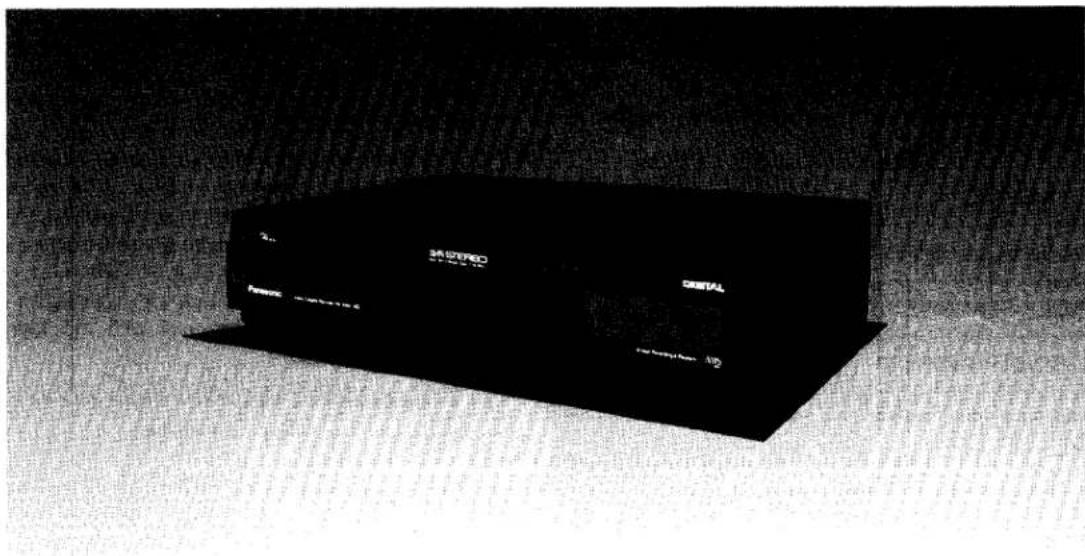
Panasonic
Before attempting to connect, operate or adjust this product, please read these instructions completely.
CONTENTS
Page
| 3 | FEATURES |
| 4 | CONTROLS AND COMPONENTS |
| 7 | PROGRAMMABLE REMOTE CONTROLLER |
| 8 | INSTALLATION |
| 9 | TUNING THE TV SET TO THE VIDEO PLAYBACK CHANNEL |
| 10 | SETTING THE TUNER IN THE VTR |
| 11 | SETTING THE CLOCK TO THE PRESENT TIME |
| 12 | THE VIDEO CASSETTE |
| 13 | PLAYBACK |
| 16 | RECORDING FROM A TV BROADCAST SIGNAL |
| 18 | HI-FI AUDIO SYSTEM |
| 19 | USING THE VTR AS A HI-FI AUDIO RECORDER |
| 20 | SUPER OTR FUNCTION (ONE-TOUCH TIMER RECORDING) |
| 21 | TIMER RECORDING |
| 24 | CAMERA RECORDING |
| 25 | DUBBING (COPYING) |
| 26 | AUDIO DUBBING |
| 27 | DIGITAL SPECIAL EFFECTS |
| 28 | VHS INDEX SEARCH SYSTEM |
| 29 | INTRO SCAN FUNCTION |
| 30 | BEFORE REQUESTING SERVICE |
| 32 | CAUTIONS |
| 33 | SPECIFICATIONS |
IMPORTANT
Your attention is drawn to the fact that recording of pre-recorded tapes or discs or other published or broadcast material may infringe copyright laws.
WARNING
TO PREVENT FIRE OR SHOCK HAZARD, DO NOT EXPOSE THIS EQUIPMENT TO RAIN OR MOISTURE.
This apparatus was produced to BS 800:1983.
FOR YOUR SAFETY
■ DO NOT REMOVE OUTER COVER.
To prevent electric shock, do not remove cover. No user serviceable parts inside. Refer servicing to qualified service personnel.
■ AC MAINS LEAD CONNECTION
The wires in the mains lead of this apparatus are coloured in accordance with the following code.
Important

As the colours of the wires in the mains lead may not correspond with the coloured markings identifying the terminals in your plug proceed as follows: The wire which is coloured BLUE must be connected to the terminal which is marked with the letter N or coloured BLACK. The wire which is coloured BROWN must be connected to the terminal which is marked with the letter L or coloured RED.
is the safety information.
FEATURES
Digital NR Switch
This switch can be used to minimize noise in all pictures played back or received through the VTR.
Digital Special Effect
The special digital picture effects can be enjoyed by using the Remote Controller.
1-Month Calendar Timer
The clock/timer of the VTR is programmed with the calendar up to the end of 2001, so it knows exactly what day of the week it is on any given date. Programming of as many as 8 timer recordings is possible up to one month in advance.
Auto Operation
The extremely convenient Auto Operation functions of this VTR include Auto Start and Auto Play when a recorded cassette is inserted, Auto Eject which indicates that an inserted cassette is not suitable for recording, Power-Off Eject for ejecting a cassette even with the VTR off, and Auto Rewind at the end of a tape. If the VTR On/Off Switch is pressed during the rewind mode including Auto Rewind, the VTR will eject the cassette and turn itself off when rewinding is completed.
Super OTR Function (One-Touch Timer Recording)
This convenient function makes it possible to easily programme the VTR for recording of TV programmes with immediate start or with start within 24 hours by precisely setting the starting time and ending time to the desired minute. When the recording ends, the VTR will automatically turn itself off.
HQ (High Quality) Picture System
Video recorders carrying the HQ symbol mark feature the new VHS High Quality Picture System. This system assures complete compatibility with VTRs that use the conventional VHS system.
Lap Time Counter
The new Lap Time Counter is a great improvement over the approximate counter systems of conventional VTRs. It gives you an exact reading of the elapsed tape time in hours, minutes and seconds, and makes it easy to calculate the tape time left on a cassette.
Digital Scanner
This Digital Scanner lets you programme timer recordings by tracing the corresponding bar codes on the supplied Programming Sheet and then transmitting the data to the VTR.
VHS Index Search System
With the Index Search function, up to 20 addresses (places where an Index signal is recorded) can be skipped to directly locate the beginning of the desired programme in forward or reverse direction in the Fast Forward or Rewind mode.
Intro Scan Function
The Intro Scan function plays back the first 10 seconds of each programme (recorded with index signal) on a tape one after another.
Hi-Fi Stereo System
Recording and Playback of "Simulcast" Sound
This VTR allows recording and playback of the stereo sound of TV programmes broadcast via "Simulcast" by connecting an FM tuner to the Audio Input Sockets.
Digital Still, Digital Still Advance and Digital Double Fine Slow Playback
Programmable Remote Controller
8 Hours Recording and Playback
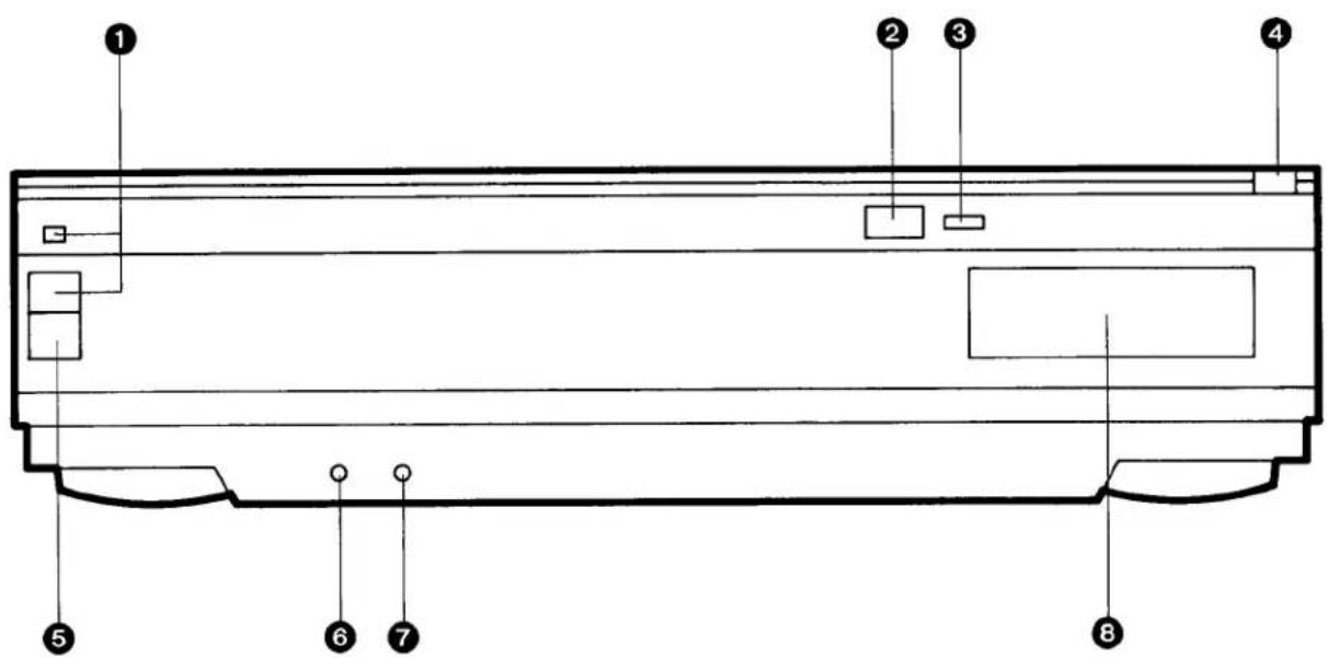
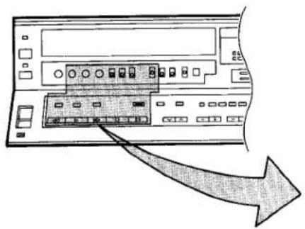
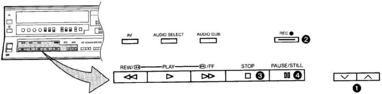
CONTROLS AND COMPONENTS
FRONT
| No. | Description | Page |
| 1 | VTR On/Off Switch with Indicator | 9 |
| 2 | Infra-red Remote Control Receiver | 7 |
| 3 | Digital Indicator | - |
| 4 | Control Panel Open Button | 4 |
| 5 | Cassette-in Indicator | 12 |
| 6 | Headphones Socket | 19 |
| 7 | Microphone Input Socket | 26 |
| 8 | Multi-Function Display | 6 |
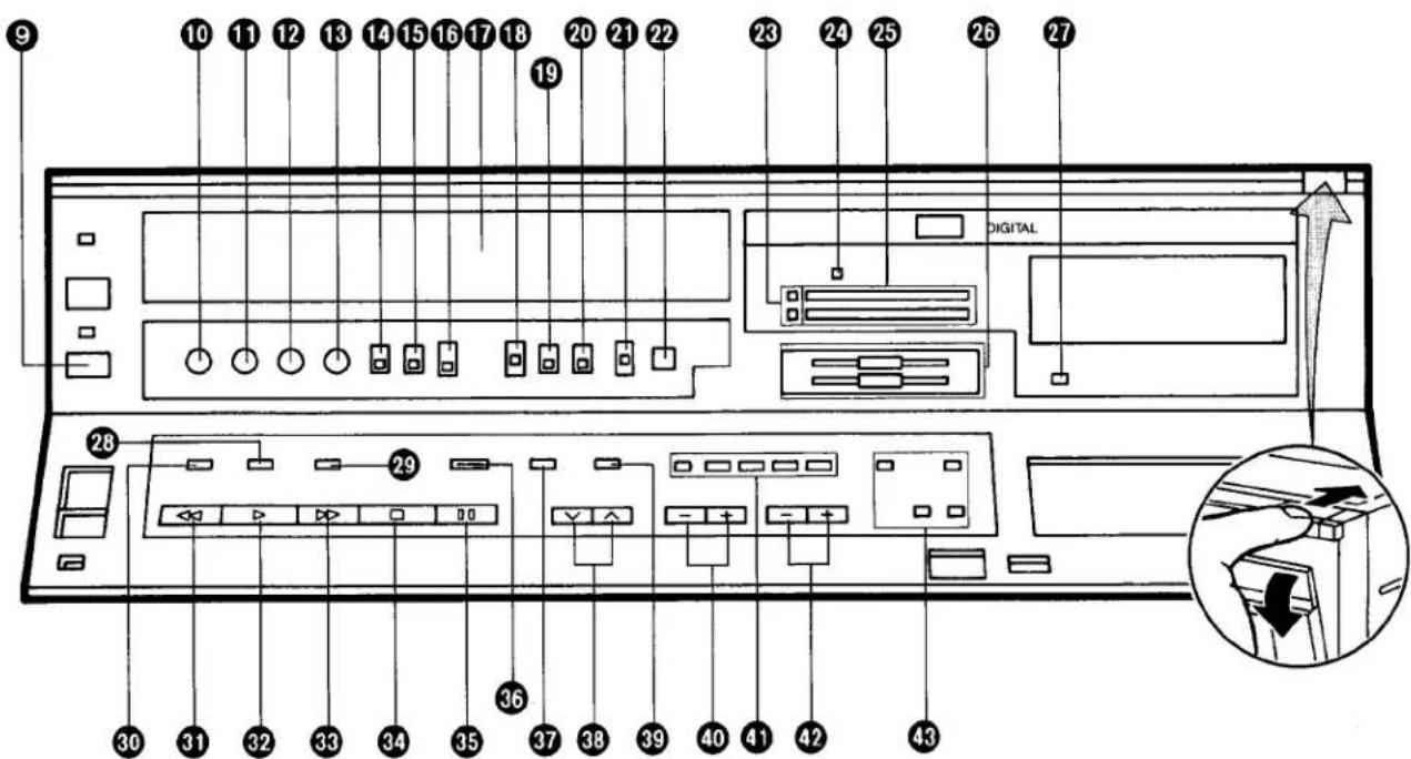
| 9 | Eject Button (▲) | 12 |
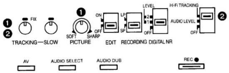
| 10 | Headphones Output Level Control | 19 |
| 11 | Tracking Control | 14 |
| 12 | Slow Tracking Control | 15 |
| 13 | Picture Sharpness Control | 14 |
| 14 | Edit Switch | 25 |
| 15 | Tape Speed Selector | 17 |
| 16 | Digital NR Switch | 13 |
| 17 | Cassette Compartment | 12 |
| 18 | Audio Level Meter Selector | 14 |
| 19 | Audio Rec Level Control Selector | 17 |
| 20 | MPX Filter Switch | 19 |
| 21 | Input Signal Selector | 19 |
| 22 | Timer Record Button | 21 |
| 23 | Audio Playback Mode Indicators | 18 |
| 24 | Simulcast Indicator | 18 |
| 25 | Audio Level Meter | 17 |
| No. | Description | Page |
| 26 | Audio Rec Level Controls | 17 |
| 27 | Audio Dubbing Indicator | 26 |
| 28 | Audio Playback Mode Selector | 18 |
| 29 | Audio Dubbing Button | 26 |
| 30 | AV Button | 9 |
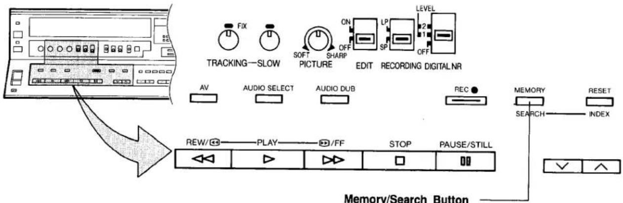
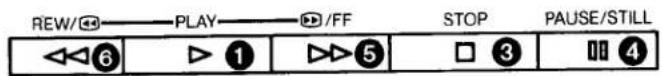
| 31 | Rewind ◀◀/Review ➕Button | 13 |
| 32 | Play Button (▶) | 14 |
| 33 | Fast Forward ▶▶/Cue ➕Button | 13 |
| 34 | Stop Button (■) | 14 |
| 35 | Pause/Still Button (■) | 14 |
| 36 | Record Button (●) | 16 |
| 37 | Memory/Search Button | 13 |
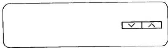
| 38 | Channel Selection Up and Down Buttons | 10 |
| 39 | Reset/Index Button | 28 |
| 40 | OTR On Buttons | 20 |
| 41 | Timer Controls | 11 |
| 42 | OTR Off Buttons | 20 |
| 43 | Tuner Set-up Controls | 10 |
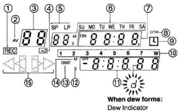
Multi-Function Display
| No. | Description | Page |
| 1 | Recording Indicator | 16 |
| 2 | AV Indicator | 25 |
| 3 | Channel Display | 10 |
| 4 | Double Speed Indicator | 15 |
| 5 | Tape Speed Indicator | 17 |
| 6 | Date Display | 11 |
| 7 | Clock Display | 11 |
| 8 | OTR Indicator | 20 |
| 9 | Timer Recording Display | 22 |
| 10 | Timer Programme Number | 21 |
| 11 | Tape Counter Display | 13 |
| 12 | Search Indicator | 13 |
| 13 | Tape Counter | 13 |
| 14 | Memory Indicator | 13 |
| 15 | Tape Running Display | 13 |
REAR
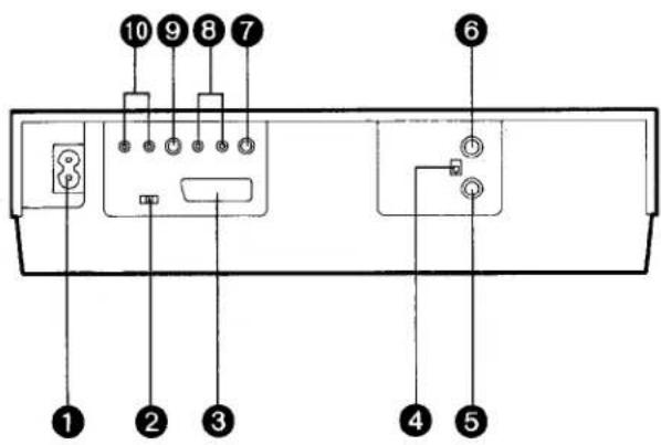
| No. | Description | Page |
| 1 | AC Mains Lead Socket | 8 |
| 2 | Colour Mode/Test Signal Switch | 9 |
| 3 | AV Socket | 8 |
| 4 | RF Signal Level Switch | 9 |
| 5 | RF Input Socket | 8 |
| 6 | RF Output Socket | 8 |
| 7 | Video Output Socket | 25 |
| 8 | Audio Output Sockets | 8 |
| 9 | Video Input Socket | 24 |
| 10 | Audio Input Sockets | 8 |
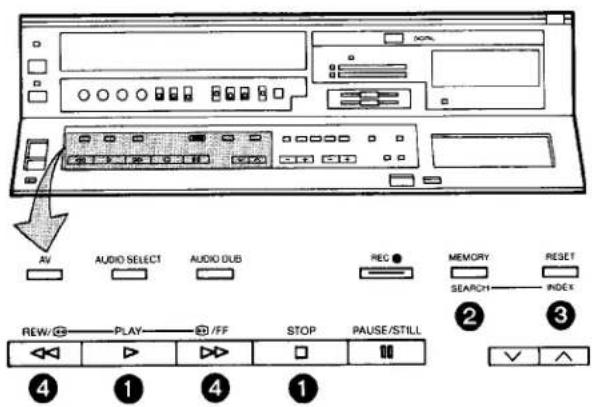
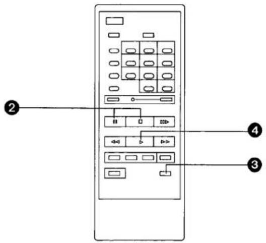
PROGRAMMABLE REMOTE CONTROLLER
Part Number: VEQ0574
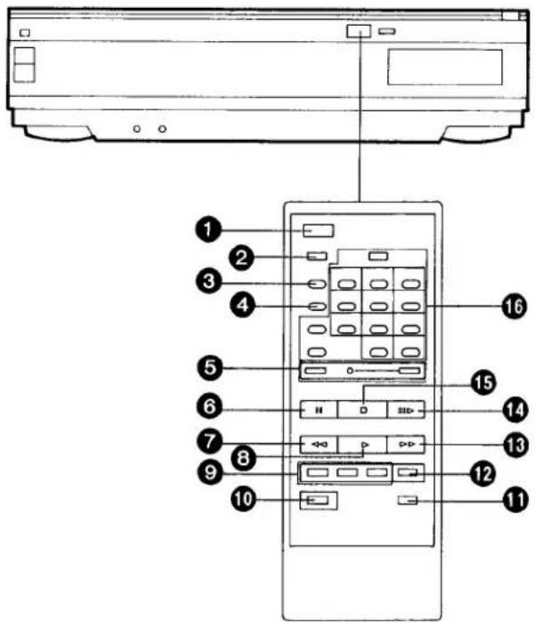
① VTR On/Off Button
② Audio Select Button
③ Memory/Search Button
4 Reset/Index Button
⑤ Record Buttons (●)
⑥ Pause/Still Button (II)
⑦ Rewind ◀◀/Review □◀ Button
8 Play Button (▶)
9 Slow Buttons
10 Digital Function Button
⑪ Intro Scan Button
12 Double Speed Playback Button (×2)
13 Fast Forward ▶▶/Cue ➕ Button
14 Still Advance Button (III)
15 Stop Button (■)
16 Timer Recording & Programme Position Selector Buttons
Power Source for the Remote Controller
The Remote Controller is powered by two IEC "R6" size batteries. The life of the batteries is about one year, however, it depends on the frequency of use. Inspect and if necessary, replace the batteries once a year.
CAUTION FOR BATTERY REPLACEMENT
- Load the new batteries with their polarities (⊕ and ⊖) aligned correctly.
- Do not apply heat to batteries, or internal short-circuit may occur.
- If you do not intend to use the Remote Controller for a long period of time, remove the batteries and store them in a cool and dry place.
- Remove spent batteries immediately and dispose of them.
- Do not use an old and a new batteries together. (Also never use an alkaline battery with a manganese battery.)
Load the batteries as follows:
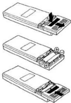
natural_image
Three-step diagram showing a device with internal components and directional arrows, no text or symbols present.① Remove the battery compartment lid.
2 Place two batteries in the battery compartment as indicated inside the battery compartment.
③ Replace the lid.
Note:
●The infra-red beam should be transmitted directly at the Infra-red Remote Control Receiver on the front of the VTR.
- Direct sunlight may interfere with the beam.
- The lightsensing angle of the Infra-red Remote Control Receiver window in the VTR is about 60°.
- The unit should be used within a range of about 7 meters from the front of the VTR.
INSTALLATION
Consult your Panasonic dealer for advice about a suitable cable to use for connection to the AV Socket. Connecting the VTR to the TV set via the AV Socket of both units assures optimum picture quality.
Connection to a TV Set without AV Socket
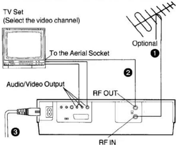
1 Connect the external aerial to the RF Input Socket on the VTR.
② Connect the aerial terminal on your TV set to the RF Output Socket on the VTR with the supplied DIN-DIN Coaxial Cable.
3 Connect the AC Mains Lead to the AC Mains Socket of the VTR, and a mains outlet.
Note:
Connect the Audio/Video Output Sockets to the Input Sockets on the TV set (if equipped with these Sockets) for watching the TV in AV mode.
Connection to a TV Set with AV Socket
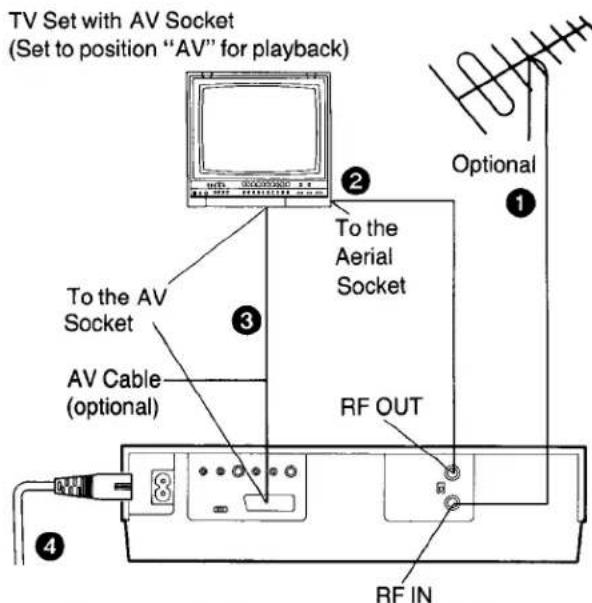
- For a suitable AV cable, consult an authorised dealer.
1 Connect the external aerial to the RF Input Socket on the VTR.
2 Connect the aerial terminal on your TV set to the RF Output Socket on the VTR with the supplied DIN-DIN Coaxial Cable.
3 Connect the AV Socket on the VTR to the AV Socket on the TV set.
- The AV Socket allows recording and playback of picture and sound. This connection can be used with TV sets which are also equipped with a AV Socket.
4 Connect the AC Mains Lead to the AC Mains Socket of the VTR, and a mains outlet.
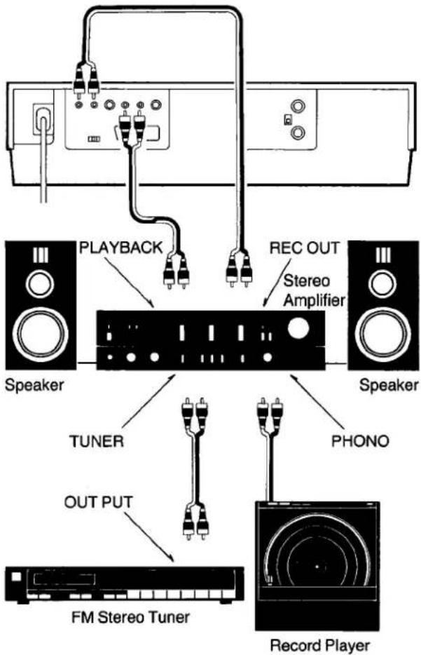
Connection to a Stereo Amplifier
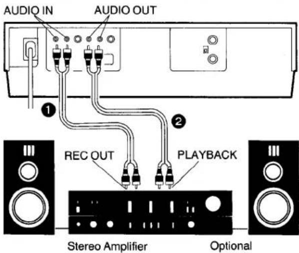
1 Connect the Audio Input Sockets on the VTR to the REC OUT Sockets on the Stereo Amplifier.
2 Connect the Audio Output Sockets on the VTR to the PLAYBACK Sockets on the Stereo Amplifier.
- If an AV cable is used for the VTR-to-TV connection and both the VTR and TV set have an "AV" position, set only one of them to "AV". If both are set to "AV", picture and sound distortion may appear with some types of TV sets.
- Some TV sets can automatically switch to the "AV" input mode when VTR playback starts via the AV cable. But some TV sets have to be switched manually to the "AV" mode.
- For recording from a TV's tuner via the AV cable, set the VTR to the "AV" mode.
TUNING THE TV SET TO THE VIDEO PLAYBACK CHANNEL
The adjustments described on this page are not necessary, if the VTR is connected to the TV set via the AV sockets or Video/Audio output terminals.
Used to attenuate the reception of the VHF and/or UHF aerial signals.
If the reception is normal, set to "HIGH". If the signal is strong (stripes appear in the upper part of the picture), set to "LOW".
1 Turn the TV set on and select the AV programme position or another programme position that is not occupied by any TV station.
② Press the VTR On/Off Switch to turn the VTR On. (FRONT SIDE)
●The corresponding indicator lights up.
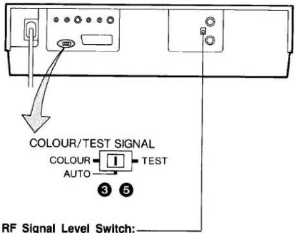
③ Set the Colour Mode/Test Signal Switch to "TEST".
4 Tune the selected programme position of the TV set to UHF approx. channel 36.
Confirm on your TV set that the received test pattern is as shown.

natural_image
Abstract black and white geometric pattern with two vertical stripes (no text or symbols)5 Set the Colour Mode/Test Signal Switch to "AUTO". Your TV is now ready to receive the RF output signal from the VTR.
- If, during recording or playback, the colour is not satisfactory, it can be stabilized by setting the Colour Mode/Test Signal Switch to "COLOUR".
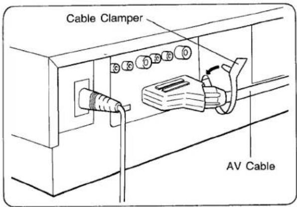
Connecting the AV Cable to the VTR
Fix the AV Cable by the accessory Cable Clamper as shown below.
SETTING THE TUNER IN THE VTR
The tuner in the VTR makes it possible to receive TV broadcasts and to record these programmes without having to turn on the TV set. The frequency band of this model extends from UHF channel 21 to 69.
Preparation
- Turn the TV set on and select the programme position (channel) which you have tuned to the video playback channel.
- Press the VTR On/Off Switch to turn the VTR on.
- Set the Input Signal Selector to "Tuner".
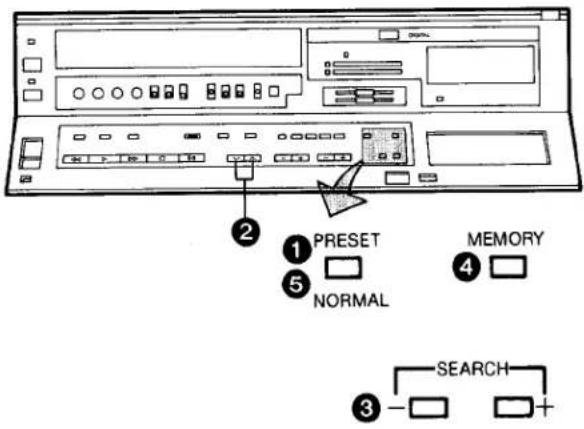
① Press the Preset/Normal Button.
The indication on the Multi-Function Display changes from the clock indication to the position indication.
2 Press the Channel Up or Down Button to select a programme position (channel) which you want to tune to a TV station.
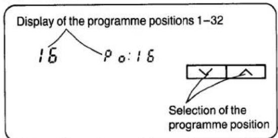
The tuner in the VTR can be preset with up to 32 stations.
③ Press the Search (+) or (−) Button.
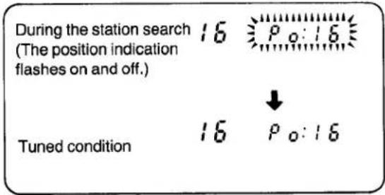
- When the tuning of the station is completed, the indication stops flashing.
- At every push of the Search (+) or (−) Button, the station will be tuned automatically.
4 Press the Memory Button.
(Programme position display frashes once.)
Repeat steps ②—④ for each channel you want to tune to a station.
5 Press the Preset/Normal Button again.
The indication on the Multi-Function Display changes to the clock indication.
SETTING THE CLOCK TO THE PRESENT TIME
The built-in digital clock employs the 24-hour system.
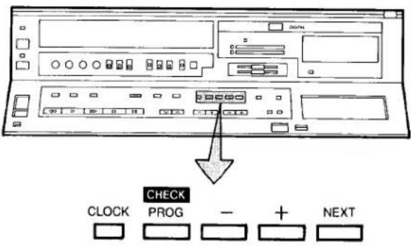
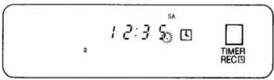
For Example: Set the clock for Saturday, September 10, 1988, 12:35.
- Connect the VTR to the mains outlet.
- Press the VTR On/Off Switch to turn the VTR On.
When connecting this VTR to the mains or after a long power failure, both the date and time indications flash.
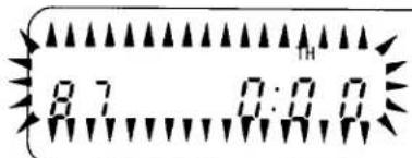
② Press the Clock Button to start the date and time setting.
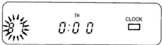
③ Press the (+) or (−) Button to set the year.
4 Press the Next Button.
⑤ Press the (+) or (−) Button to set the month.
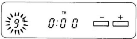
6 Press the Next Button.
7 Press the (+) or (−) Button to set the date.
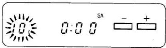
8 Press the Next Button.
9 Press the (+) or (−) Button to set the hour.
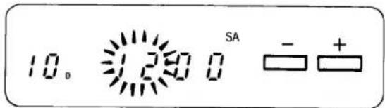
10 Press the Next Button.
11 Press the (+) or (−) Button to set the minute.
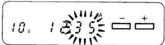
12 Press the Clock Button when the present time becomes exactly 12:35'00".
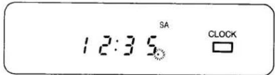
At every push of the Next Button, the flashing indication changes in the following order.
YEAR→MONTH→DATE→HOUR→MINUTE
- The timer back-up system maintains the clock operation for about 30 seconds in case of a power failure. However, it takes more than 60 minutes for the back-up circuit to become operational, after the VTR is connected to the mains.
- The Timer Record Function should be set to "Off", otherwise the VTR cannot be operated normally. In this case, the Timer Record Indicator "☐" will flash to warn you.
- During date setting, the corresponding day is simultaneously set.
THE VIDEO CASSETTE
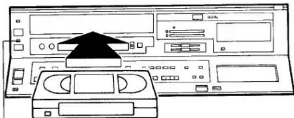
Inserting a Video Cassette (Auto Operation)
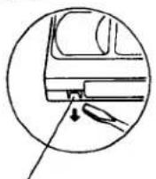
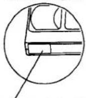
1 Insert the video cassette as shown. The VTR will be turned on automatically and the cassette will be automatically drawn into the VTR.
natural_image
Line drawing of a computer monitor setup with an open CD and a black arrow pointing to the front panel (no text or symbols)2
② When a video cassette is inserted, the “○○” mark will appear.
Notes:
- When a video cassette with broken out erasure prevention tab (for example a pre-recorded tape) is inserted, playback will start immediately.
- Use VHS video cassette tapes only.
- We recommend the "Panasonic Hi-Fi" high grade video cassette tapes for improved picture and sound quality.
Removing a Video Cassette
③ Press the Eject Button (▲).
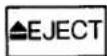
Simply press the Eject Button; the VTR turns itself on, ejects the cassette and turns itself off again.
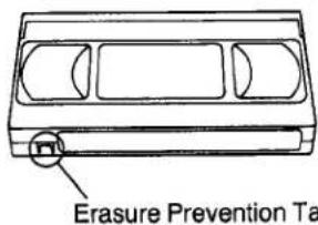
To prevent accidental erasure
Break off the tab with a screwdriver.
To record again
Cover the hole with adhesive tape.
PLAYBACK
Preparation
- Press the VTR On/Off Switch to turn the VTR on.
- Make sure that the Timer Record Function is set to "Off".
- Insert a recorded video cassette.
- Turn the TV set on and select the video playback channel.
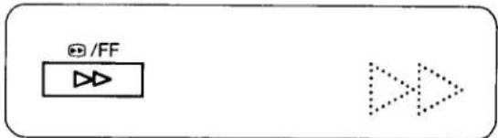
Rewind and Fast Forward
Press the Rewind ◀◀/Review ◀◀ Button to rewind the tape.
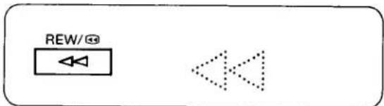
Press the Fast Forward ▶▶/Cue ▶▶ Button to wind the tape forward rapidly.
Lap Time Counter
It shows the elapsed recording or playback time.
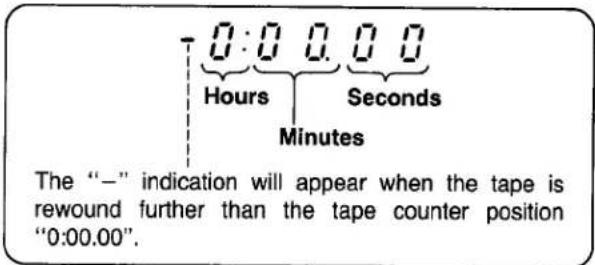
- If the figures on the Tape Counter do not change during Fast Forward, Rewind or any of the Playback functions, this means that nothing is recorded on that tape section.
- The Tape Counter is automatically reset to "0:00.00" when the video cassette is ejected.
Repeatedly pressing this button will change the indication in the following order: "M" (Memory) → "S" (Search) → both indications are off → "M"...
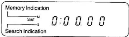
Memory Function
The Memory function makes it simple and fast to find a certain position on the tape later again, simply by pressing the Reset/Index Button at that position to set the tape counter to "0:00.00" and by pressing the Memory/Search Button. During Rewind or Fast Forward, the tape will then stop at approximately the desired position.
Digital NR Switch
This switch can be used to minimize noise in all pictures that are played back or received through the VTR. Usually this switch is set to position "1".
When the picture is hard to see due to excessive picture noise, set the switch to position "2".
- When the switch is set to position "2" or "1", an after-image may occur.
Auto Operation
When inserting a video cassette which has the erasure prevention tab removed playback will start automatically.
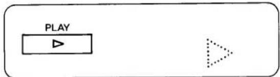
① Normal Playback
Press the Play Button (▶).
- Adjust the Tracking Control on the VTR if the image is partially obscured by bands of noise.
●Control the picture as you like with the Picture Sharpness Control (sharp or soft contours).
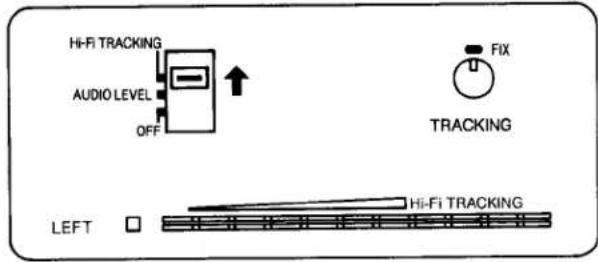
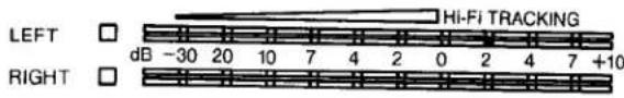
② Adjustment of the HI-FI Audio Tracking
This adjustment may be necessary when playing back a tape which was recorded on another hi-fi VTR. Set the Audio Level Meter Selector to "Hi-Fi Tracking" and slowly adjust the Tracking Control while observing the Audio Level Meter, for highest possible meter Indication.
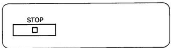
③ To Finish Playback
Press the Stop Button (■) to stop the playback.
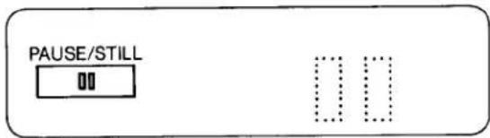
4 Digital Still Playback
When the VTR is in the playback mode, press the Pause/Still Button (III) to view a still-picture. To continue the normal playback, press this button again.
⑤ Cue Playback
When the Fast Forward ▶▶/Cue ▶▶ Button is kept pressed while the VTR is in the playback mode, the tape will be played back at high speed in forward direction.
6 Review Playback
When the Rewind ◀◀/Review ⏻ Button is kept pressed while the VTR is in the playback mode, the tape will be played back at high speed in reverse direction.
To make possible Cue or Review playback without having to keep the respective button pressed, first press the Memory/Search Button so that the Search Indicator "S" appears in the Multi-Function Display, and then press the Fast Forward ▶▶/Cue Button ➕ or the Rewind ◀◀/Review ➔◀ Button.
To switch the VTR back to normal playback, press the Play Button (▶).
- When Cue or Review playback continues for more than 10 minutes, the VTR will automatically switch back to the normal playback mode.
PLAYBACK BY USING THE REMOTE CONTROLLER
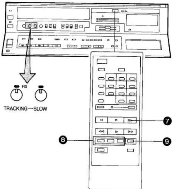
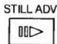
7 Digital Still Advance Playback
Press the Still Advance Button (III) while the VTR is in the still playback mode. Each time you press this button, the still-picture will advance one single field.

8 Digital Double Fine Slow Playback
During normal playback, the Slow-motion playback can be activated by pressing the Slow Button. The slow-motion playback speed can then be varied by using the Slow (+) or (−) Button.
When changing the slow-motion playback speed, indicator flashes.
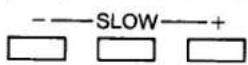

- Press the Play Button (▶) to continue the normal playback.
- If the Slow playback operation continues for more than 5 minutes, the VTR automatically switches over to the stop mode.
- While playing back a tape in the Still or Fine Slow playback mode on a TV set equipped with an automatic vertical hold control, the picture may shake vertically. In this case, set the TV set's vertical hold (AUTO/MANUAL) selector to the "MANUAL" position, and adjust the vertical hold control, if it is accessible; otherwise consult qualified service personnel.
Slow Tracking Control
- When noise bars appear during Still Advance or Fine Slow playback, switch over to slow playback and adjust the Slow tracking Control to reduce the noise bars.
- It may not be possible to eliminate the noise bars completely.
9 Double Speed Playback
When the VTR is in the playback mode, press the Double Speed Playback Button to view the action at twice the normal playback speed. To change back to normal playback, press the Play Button.
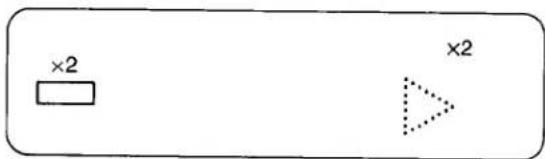
- The sound will be played back only during normal playback.
- If you leave the VTR in the still playback mode for more than 5 minutes, the VTR will automatically switch over to the Stop mode to protect the tape and the video heads.
- Noise which takes the form of horizontal bars appears on the TV in the Cue and Review playback modes. This is not an indication of a malfunction.
- The top of the picture may become distorted in the Cue, Review or Still (LP) mode. This is not an indication of a malfunction.
- When the picture rolls vertically in the Cue or Review mode, adjust the vertical hold control on the TV set.
-
Immediately after starting Cue or Review playback, the picture may be distorted. Also, when these modes are cancelled, some momentary picture distortion may occur. However, this is not due to any malfunction.
•In "LP" mode only: -
During any playback mode other than normal playback, the picture may have some noise bars, the colour may be unstable, or a black and white picture may appear.
-
When playing back a tape which was recorded on another VTR, it may be necessary to adjust the Tracking Control. In some cases the picture quality may still be inferior. This is due to limitation of format.
- At present UK TV Broadcasts are not in "STEREO": When playing back off-air recordings of mono TV Programmes, the "Left" and "Right" indicators of the Audio Playback Mode Indicators light up, this is only to confirm that the sound is being reproduced from the hi-fi audio tracks and does not infer that the recording is necessarily in stereo.
RECORDING FROM A TV BROADCAST SIGNAL
Preparation
- Press the VTR On/Off Switch to turn the VTR on.
●Make sure that the Timer Record Function is set to "Off".
- Reset the Tape Counter to "0:00.00".
- Set the Input Signal Selector to "Tuner".
- Insert a video cassette with the erasure prevention tab intact.
- Set the Audio Rec Level Control Selector to "AGC".
- Set the Tape Speed Selector to "SP" or "LP".
1 Select on the VTR, the programme position (channel) to be recorded. In order to confirm proper reception, turn on the TV set and select the video playback channel.
② Press the Record Button (●).
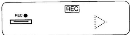
When a video cassette with broken out tab is inserted, it will be ejected automatically.
- During recording, the programme position (channel) on the VTR cannot be changed.
- To start a recording with the Remote Controller, press the two Record Buttons on the Remote Controller simultaneously.
To Finish the Recording
③ Press the Stop Button (■).
If You Wish to Avoid Recording Unwanted Material
4 Press the Pause/Still Button (Ⅲ) to stop the tape temporarily.
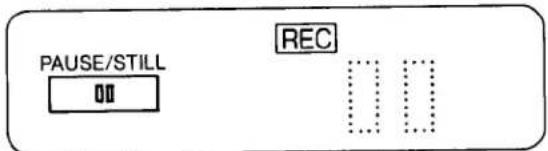
- Press the Pause/Still Button (II) again to continue the recording.
- If you leave the VTR in the pause mode for more than 5 minutes, the VTR will automatically switch over to the stop mode to protect the tape and the video heads.
Recording One TV Programme While Watching Another
- Record (following steps ① and ②).
- Select the desired programme position (channel) on your TV set.
- When recording in the LP mode, we recommend the use of "Panasonic Hi-Fi" high grade video cassette tapes for improved picture and sound quality.
- The Digital NR Switch can also be used for recording to reduce picture noise.
flowchart
graph TD
    A["Audio Level"] --> B["Tape Speed Indicator"]
    B --> C["Hi-Fi TRACKING"]
    B --> D["MANUAL"]
    B --> E["AGC"]
    B --> F["AUDIO RECORDING"]
    G["LP"] --> H["RECORDING"]
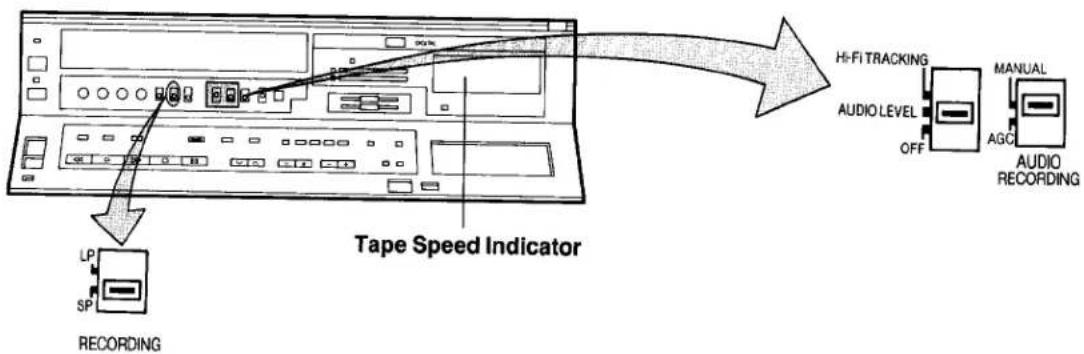
Tape Speed Selector
Tape Speed Selector
For recording either of two tape speeds can be selected. During playback the recorder selects automatically the correct speed.
Select the desired tape speed with the Tape Speed Selector before recording.
- Set to the "SP" position for normal speed.
- Set to the "LP" position for slow speed.
The corresponding indicator (SP or LP) lights up during recording and playback in the Multi-Function Display.
It is not recommended to change from the SP to the LP mode or vice versa in the middle of recording. Even if the switching is done while the VTR is in the pause mode, picture distortion will occur at the switching point during playback.
Manual Adjustment of the Audio Recording Level
Manual adjustment of the Audio recording level may be desirable when using the VTR as a hi-fi audio recorder or when producing your own video tapes.
- Set the Audio Level Meter Selector to "Audio Level" and Audio Rec Level Control Selector to "Manual" and adjust the recording volume with the Audio Rec Level Controls, while observing the Audio Level Meters. The recording level for the right and left channel can be adjusted individually.
(It is recommended to adjust so that peaks in the audio level reach about +4 dB.)
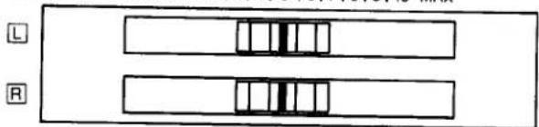
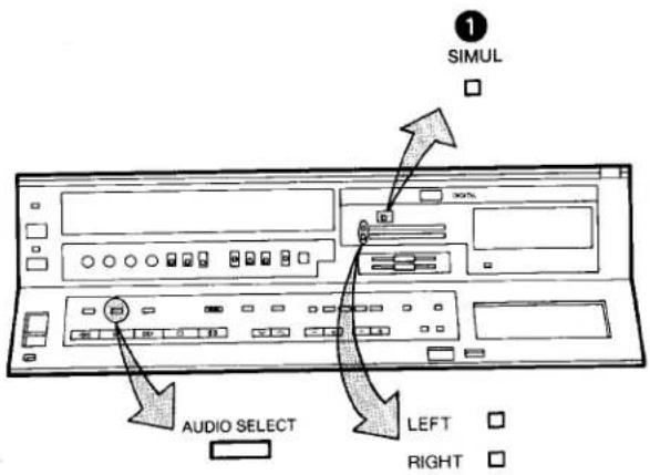
SIMUL
□
AUDIO
REC LEVEL MIN 011121314151617181910 MAX
natural_image
Pure diagram of two parallel rectangular blocks with internal vertical divisions, no text or symbols present- For all Timer Recordings and also for normal recordings of TV programmes, the Audio Rec Level Control Selector is usually set to "AGC" for automatic adjustment of the audio recording level.
- When the Input Signal Selector is set to "Line/Audio", the level of the sound to be recorded on the hi-fi audio tracks and the "normal" audio track can be manually adjusted together.
When this selector is set to "Tuner" or "Simul", manual adjustment of the audio recording level is only possible for the sound which is to be recorded on the hi-fi audio tracks. The sound to be recorded on the "normal" audio track will be adjusted automatically.
HI-FI AUDIO SYSTEM
Recording of Simulcast Sound
Preparation
- Connect your VTR to the Stereo Amplifier and FM Stereo Tuner as described on page 19.
●Tune the FM Stereo Tuner to the desired station.
① Set the Input Signal Selector to "Simul". The "Simul" indicator lights up.
- The operation procedure is the same as for normal recording; see "Recording from a TV broadcast signal" on page 16.
While this switch is in the "Simul" position, the sound portion of the TV broadcast signal will be recorded only on the "normal" sound track. And the stereo sound signal received via the FM tuner will be recorded on the hi-fi sound tracks.
Playback (or Monitoring during Recording)
Press the Audio Playback Mode Selector to select the desired sound mode.
At the every push of this button, the audio playback mode changes as follows:

and the Left and Right Indicators show which sound mode is selected in the following way.
Stereo: Both the Left and Right Indicators are lit.
Left: The Left Indicator is lit.
Right: The Right Indicator is lit.
Normal: Both the Left and Right Indicators are not lit.
- The Audio Rec Level Control Selector must be set to "AGC", if no manual adjustment is to be carried out.
- If a video cassette recorded on this VTR with stereo sound is played back on a conventional VHS video recorder, the sound will be reproduced from the "normal" audio track (in mono).
- If a video cassette recorded on a conventional VHS stereo video recorder is played back on this VTR, the sound reproduction of a stereo programme will be in mono. In case of a recorded bilingual programme, both language versions are reproduced mixed together (and are therefore not intelligible).
| Playback of Programmes Recorded on this VTR (or another VHS Hi-Fi Video Recorder) | Playback of Programmes Recorded on a Conventional VHS Stereo Video Recorder | ||
| Stereo Programmes | Mono Programmes | Stereo Programmes | |
| STEREO | Left+Right Channels (Stereo) | Mono | —— |
| LEFT | Left Channel | Mono | —— |
| RIGHT | Right Channel | Mono | —— |
| NORMAL | Mono | Mono | Left+Right Mixed |
USING THE VTR AS A HI-FI AUDIO RECORDER
flowchart
graph TD
    A["MIN PHONES LEVEL"] --> B["Headphones (Optional)"]
    B --> C["HO-FT TRACKING"]
    C --> D["AUDIO LEVEL OFF"]
    D --> E["MANUAL AUDIO RECORDING ON MPX FILTER"]
    E --> F["LINE/AUDIO TUNER SIMUL INPUT SELECT"]
    style A fill:#f9f,stroke:#333
    style B fill:#ccf,stroke:#333
    style C fill:#cfc,stroke:#333
    style D fill:#fcc,stroke:#333
    style E fill:#cff,stroke:#333
    style F fill:#ffc,stroke:#333
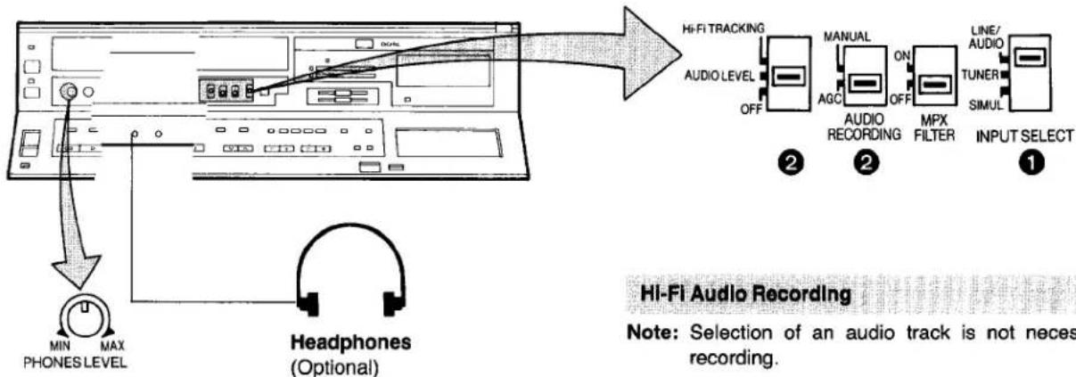
Headphones Output Level Control
Hi-Fi Audio Recording
Note: Selection of an audio track is not necessary for recording.
1 Set the Input Signal Selector to "Line/Audio".
② For automatic adjustment of the audio recording level, set the Audio Rec Level Control Selector to "AGC". Set the Audio Level Meter Selector to "Audio Level".
- To start the recording, press the Record Button (●).
③ To achieve smooth transitions between adjoining recordings, see notes on page 25.
HI-FI Audio Playback
- Press (for playback of both mono and stereo recordings) the "Audio Playback Mode Selector Button" repeatedly so that the "Left" and "Right" Audio Playback mode Indicator light up.
- To start the playback, press the Play Button (▶).
Adjustment of the Hi-Fi Audio Tracking
This adjustment may be necessary when playing back a tape which was recorded on another hi-fi VTR.
Set the Audio Level Meter Selector to "Hi-Fi Tracking" and slowly adjust the Tracking Control while observing the Audio Level Meter, for highest possible meter indication.
- If the sound is impaired by high frequency distortion when recording from an FM tuner, set the MPX Filter switch to "On". If there is no distortion when recording from an FM tuner, and for all other recordings, set this switch to "Off".
Preparation
- Connect the VTR to the hi-fi audio system.
(Example of a connection diagramme is shown). - Turn on the VTR and insert a video cassette with the erasure prevention tab intact.
- Switch on the hi-fi audio system and select an audio source.
- For "Manual Adjustment of Audio Recording Level", see page 17.
SUPER OTR FUNCTION (ONE-TOUCH TIMER RECORDING)
This convenient function makes it possible to easily programme the VTR for recording of TV programmes with immediate start or with start within 24 hours by precisely setting the starting time and ending time to the desired minute, and the VTR will automatically turn itself off when the recording ends.
Preparation
●Make sure that the clock shows the present time correctly.
- Press the VTR On/Off Switch to turn the VTR On.
- Insert a video cassette with the erasure prevention tab intact.
- Set the Input Signal Selector to "Tuner".
- Set the Audio Rec Level Control Selector to "AGC".
- Set the Tape Speed Selector to "SP" or "LP".
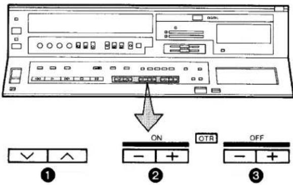
It is possible to programme an OTR recording for a TV programme which will start immediately or within the next 24 hours.
(For example, OTR recording of a TV programme broadcast from 10:30 to 11:00.)
1 Select the programme position (channel) to be recorded.
2 Press the OTR On (+) or (−) Button to set the OTR starting time to 10:30.
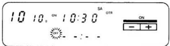
●The "OTR" Indicator will be displayed.
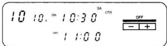
③ Press the OTR Off (+) or (−) Button to set the OTR ending time to 11:00.
When the tab of the inserted video cassette is broken out, it will be ejected automatically.
- When quickly and repeatedly pressing the OTR On (+) or (−) Button or the OTR Off (+) or (−) Button, the corresponding time indication changes in 1-minute steps. When it is kept pressed, the indication changes in 10-minute steps.
- After selecting the delay time for the OTR start in step ②, the OTR Off Button must be pressed within 8 seconds to select the OTR duration, otherwise the selected delay time will be cancelled.
- The VTR will automatically switch off, when the OTR is completed. To turn the VTR on again, press the VTR On/Off Switch.
OTR Function with Immediate Start
Perform the operation steps ① and ③.
- When the tape reaches its end during an OTR the VTR will turn itself off.
- Make sure that the OTR Function (One-Touch Timer Recording) does not overlap a programmed timer recording. An OTR always takes precedence over a timer recording.
- If you want to confirm the present time or the tape counter position before the programmed OTR is performed, or to check the tape counter position during the OTR, press the Check/Programme Button. To return the display to the previous indication, press this button once more.
- It is possible to change the OTR starting time or the ending time before the recording starts.
- It is possible to perform any VTR operation (except timer recording) until the recording starts.
- It is possible to change the OTR ending time even during the recording.
- To interrupt an OTR, press the VTR On/Off Switch to turn the VTR off.
TIMER RECORDING
The programming of timer recordings is possible both on the VTR itself and via the Remote Control Unit.
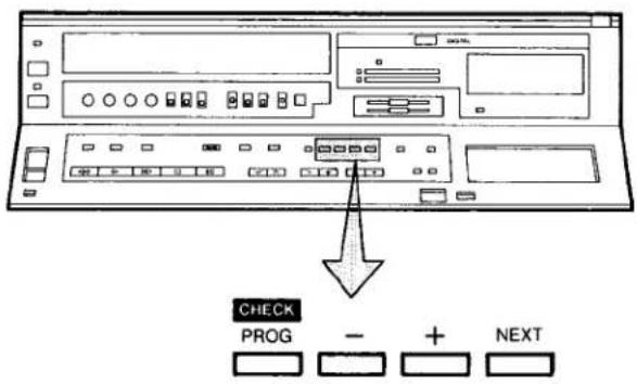
Programming of Timer Recordings with the Remote Controller
The Timer Recording Buttons (Check/Programme, Next, Timer record) of the Remote Controller have the same functions as the Check/Programme, Next, Timer Record Buttons on the VTR. Therefore, instead of using the (+) and (−) Buttons on the VTR, the Timer Recording & Programme Position Selector Buttons of the Remote Controller can be used to programme timer recordings.
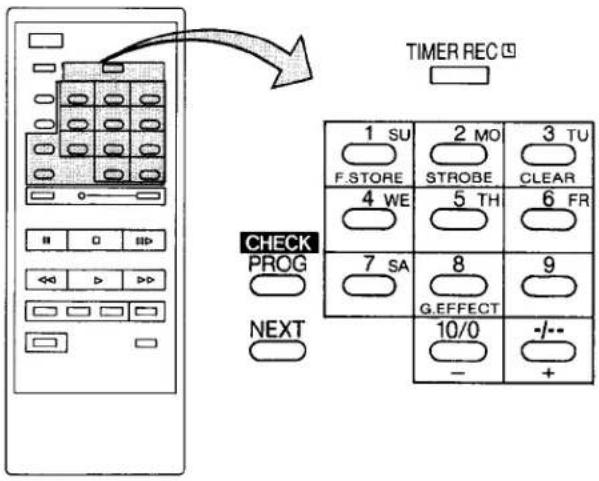
How to Select the Programme Position (Channel)
| select channel | press button | |
| 1-9 | respective channel | |
| 10 | ||
| 20 | ||
| 11-32for example 32 | ||
If more than 5 seconds pass between the first, second and third push, the channel will not be changed normally.
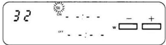
How to Set the Date and the Starting & Ending Times for Timer Recordings
The date and time can be set by directly pressing the number buttons (1 su \~ 9). When two buttons have to be pressed (for example, when setting the date to a day of the month between 10 and 31, the hour between 10 and 23, the minute between 10 and 59), the second button must be pressed within 2 seconds after pressing the first button.
Preparation
●Make sure that the clock shows the present time correctly.
●Make sure that the VTR is turned on.
●Make sure that the Timer Record Function is set to "Off".
- Set the Input Signal Selector to "Tuner".
- Insert a video cassette with the erasure prevention tab intact.
- Set the Audio Rec Level Control Selector to "AGC".
- Set the Tape Speed Selector to "SP" or "LP".
For Example:
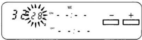
Programming a timer recording for a TV programme that will be broadcast on Wednesday, September 28, from 20:00 to 22:45, on programme position (channel) 32, on timer programme number 2. (Present date=September 10, 1988)
1 Press the Check/Programme Button to select the next unoccupied timer programme number.
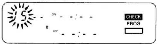
2 Press the (+) or (−) Button to select the programme position (channel) on which the TV programme will be broadcast.
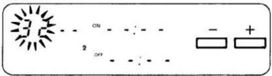
③ Press the Next Button.
4 Press the (+) or (−) Button to set the date.
5 Press the Next Button.
6 Press the (+) or (−) Button to select the hour of the starting time of the TV programme.
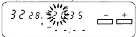
7 Press the Next Button.
8 Press the (+) or (−) Button to select the minute of the starting time of the TV programme.
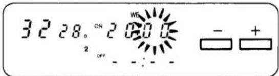
9 Press the Next Button.
10 Press the (+) or (−) Button to select the hour of the end time of the TV programme.
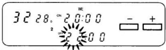
11 Press the Next Button.
12 Press the (+) or (−) Button to select the minute of the end time of the TV programme.
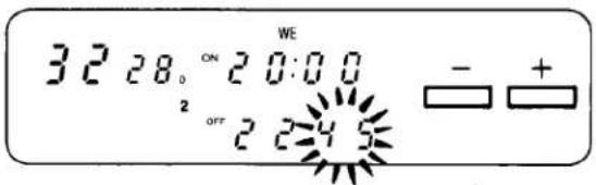
13 Press the Timer Record Button.
For Everyday Recording
For example:
Programme time for timer recording every day from 20:00–22:45 on timer programme number 7.
Programming for everyday recording can be made on any of the timer programme numbers 1–7.
Execute the operation steps ① to ③.
4 Press the (−) Button once, so that all day indications will appear together.
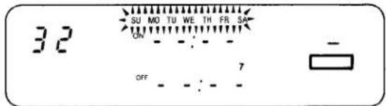
When programming an everyday recording with the Remote Controller, press the 10/0 key twice to make all day indications appear together.
Perform the operation steps ⑤ to ⑬.
For Everyweek Recording
For Example:
Programming a timer recording for a TV programme that is broadcast every week on Sunday, from 20:00 to 22:45.
① Press the Check/Programme Button 8 times, so that "W" indication will appear.
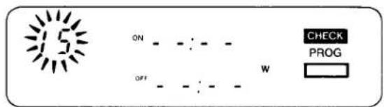
② Press the (+) or (−) Button to select the programme position (channel) on which the TV programme will be broadcast.
③ Press the Next Button.
④ Press the (+) or (−) Button to select the day of the week, on which the programme will be broadcast.
When programming an everyweek recording with the Remote Controller, press any of 7 keys (1 su \~ 7 sa) to select the day of the week.
Perform the operation steps ⑤ to ⑬ described on page 22.
To Confirm the Programme of a Timer Recording
Make sure that the VTR is turned on.
Select the programme number to be checked, by repeatedly pressing the Check/Programme Button.
The preset channel and start and ending times of the timer recording will be indicated for about 25 seconds.
When the Timer Record Function is set to "On", they will be indicated for about 8 seconds.
To Cancel a Timer Recording
Make sure that:
the VTR is turned on,
the Timer Record Function is set to "Off".
1 Press the Check/Programme Button repeatedly, until the number of the timer programme that you want to cancel is displayed.
2 Press the (+) and (−) Button simultaneously for more than 3 seconds.
- It is not possible to cancel a programmed timer recording with the Remote Controller.
- It is impossible to confirm programmes of timer recordings while an OTR is being performed.
- To turn the VTR on and use it for playback or recording before the timer recording is performed, set the Timer Record Function to "Off".
- When the Timer Record Function is set to "On" but no video cassette is inserted or no timer recording has been programmed, the Timer Recording Indicator will flash to inform that the timer recording cannot be performed.
- After the programmed timer recording has been made, set the Timer Record Function to "Off", otherwise the VTR cannot be operated normally.
- During recording, the programme position (channel) on the VTR cannot be changed.
- When you want to watch TV after setting a timer recording, select the desired channel on the TV set.
- To cancel a timer recording during recording, set the Timer Record Function to "Off".
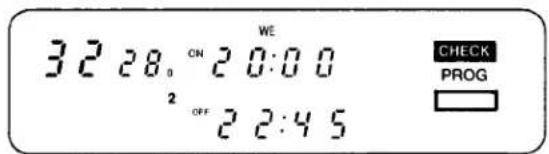
AUDIO DUBBING
Note that the original sound on the "normal" (mono) sound track will be completely erased during audio dubbing.
Preparation
- Press the VTR On/Off Switch to turn the VTR on.
- Set the Input Signal Selector to "Line/Audio".
- Insert a video cassette with the erasure prevention tab.
- Reset the Tape Counter to "0:00.00".
●Turn the TV set on and select the video playback channel. - Set the Audio Rec Level Control Selector to "AGC".
- Select the "normal" (mono) sound track by repeatedly pressing the Audio Playback Mode Selector until the Audio Playback Mode Indicators "Left" and "Right" are not lit.
1 Press the Play Button (▶) to look for the point where you want to start the audio dubbing.
2 Press the Pause/Still Button (■) at the exact point where you want to start the audio dubbing.
③ Press the Audio Dubbing Button (the indicator will light up).
AUDIO DUB

AUDIO DUB
4 Press the Pause/Still Button (11) once again to release the tape from pause, and at the same time start the operation of the audio source. The audio dubbing will start.
5 Press the Stop Button (■) to stop the audio dubbing.
- Sound recorded by using the audio dubbing function is recorded on the "normal" audio track (always in mono).
- For playback, select the "normal" (mono) sound track by repeatedly pressing the Audio Playback Mode Selector until the Audio Playback Mode Indicators "Left" and "Right" are not lit.
- When a microphone is used for dubbing, do not place it near the speaker of your TV to prevent howling noise (acoustic feedback).
- If the erasure prevention tab of the cassette is missing, no audio dubbing can be made.
- Audio dubbing is not possible on the portion of the tape which does not have any picture recorded on it.
- It is normal to have a slight interruption of sound at the point where audio dubbing ends and original sound starts.
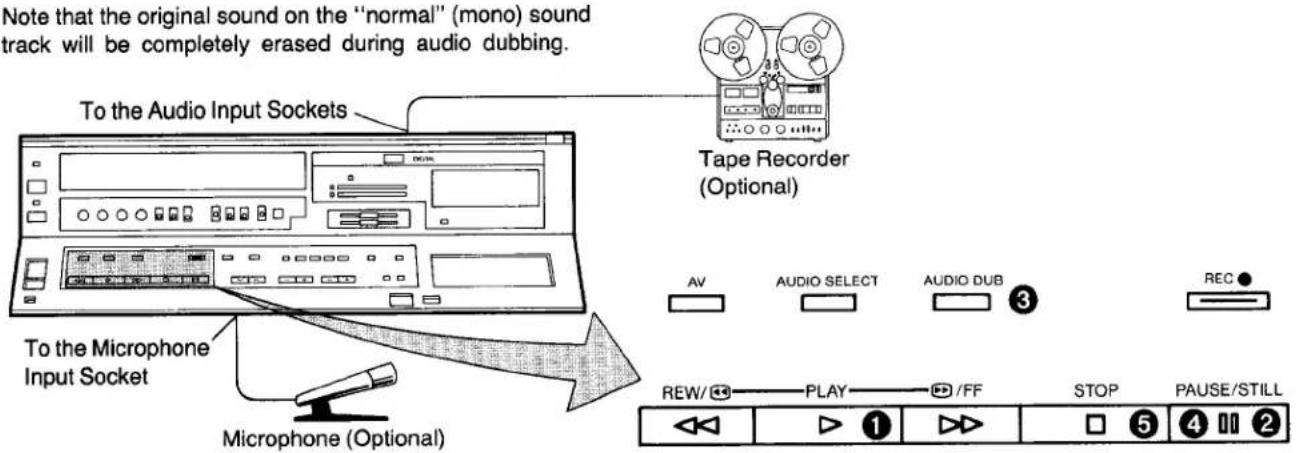
DIGITAL SPECIAL EFFECTS
The special digital picture effects can be enjoyed by using the Remote Controller.
- To operate these digital functions, press the Digital Function Button together with the desired function button on the Remote Controller.
Digital Frame Store
This function freezes the playback picture not only of video tapes, but also of TV broadcasts (received with the TV tuner in the VTR) and pictures input from external sources, and gives a still-picture. The reproduction of the sound will continue normally.
1 Press the F. Store Button, while pressing the Digital Function Button, to freeze the picture.
5 To return to the normal moving picture, press the Clear Button or F. Store Button while pressing the Digital Function Button.
Digital Strobe
This function makes possible playback with a strobe-picture-like effect.
② Press the Strobe Button, while pressing the Digital Function Button, to start the strobe picture effect.
4 The intervals of the strobe can be varied between 1 and 16 second by pressing the (+) or (−) Button while pressing the Digital Function Button.
5 To return to the normal moving picture, press the Clear Button or F. Store Button while pressing the Digital Function Button.
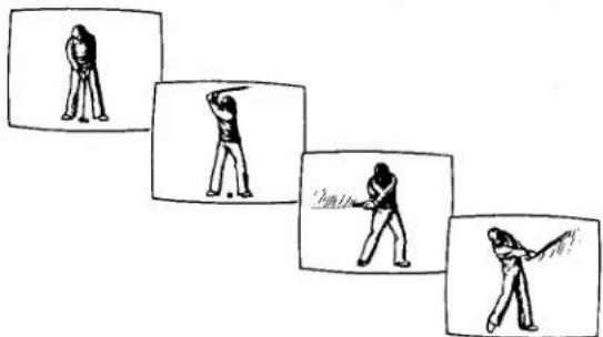
Digital Graphic Effect
③ Press the G. Effect Button while pressing the Digital Function Button.
natural_image
Black and white photo of a person standing at night with a bright object in the foreground (no visible text or symbols)5 To return to the normal moving picture, press the Clear Button or G. Effect Button while pressing the Digital Function Button.
- Of these digital picture effects, only the Graphic Effect mode can be recorded on this VTR.
- In the Digital mode, the picture may vibrate vertically, be distorted and the colour may be unstable. However, this is not due to any mulfuction.
- If a tape of inferior quality that was recorded on another VTR is played back on this VTR and the Digital Frame Store or the Digital Strobe function is used, the upper part of the picture may be distorted. In this case, adjust the tracking control. However, it may not be possible to completely eliminate the distortion.
flowchart
graph LR
    A["20"] --> B["19"]
    B --> C["2"]
    C --> D["1"]
    D --> E["1"]
    E --> F["2"]
    F --> G["3"]
    G --> H["20"]
    I["Next Programme"] --> J["Second Programme Ahead"]
    J --> K["Twentieth Programme Ahead"]
    L["Programme Now Being Played Back"] --> M["Previous Programme"]
    N["Backward Direction"] --> O["Forward Direction"]
    P["Index Signal"] --> Q["20"]
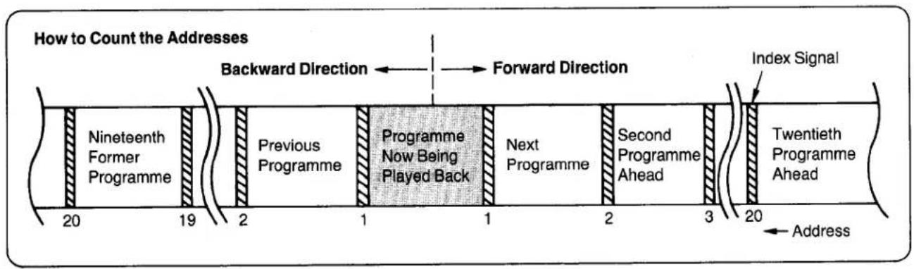
With the Index Search function, up to 20 addresses (places where an index signal is recorded) can be skipped to directly locate the beginning of the desired programme in forward or reverse direction in the Fast Forward or Rewind mode.
A special index signal (for use of the VHS Index Search function) is automatically recorded every time the Record Button is pressed. If you want to record an additional index signal during the recording of a programme, press the Record Button again at the desired point.
① Press the Play Button (▶) or Stop Button (■).
② Press the Memory/Search Button twice.
- The indication "S" appears on the Multi-Function Display.
③ Repeatedly press the Reset/Index Button to select the desired address.
The number of the selected address is shown on the Multi-Function Display.
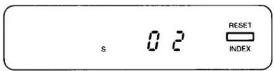
4 Press the Rewind ◀◀/Review ▶ or Fast Forward ▶▶/Cue ▶ Button to start the VHS Index Search function (the VTR will switch to the rewind or fast-forward mode).
- Every time an index signal (address) is skipped the number in the Address Indication decreases by one.
- When the preset address is reached, the Tape Counter Indication will appear in place of the Address Indication, and the normal playback will start on other VTRs which do not have this function.
-
To abort the Index Search function midway, press the Play or the Stop Button.
-
If the recording is stopped temporarily by pressing the Pause Button and is later resumed the index signal will not be recorded at that position.
- It is impossible to record only index signals onto a tape that has already been recorded.
- If a tape position without any recording is passed during the Index Search function, that position may be counted as an address.
- The Index Search function can only count the addresses correctly, if the index signals are spaced at least 2 minutes in the SP mode and 5 minutes in the LP mode.
- If the Index Search function is started extremely close to the beginning of the next programme (address) or from the beginning of the tape, the first address may not be counted.
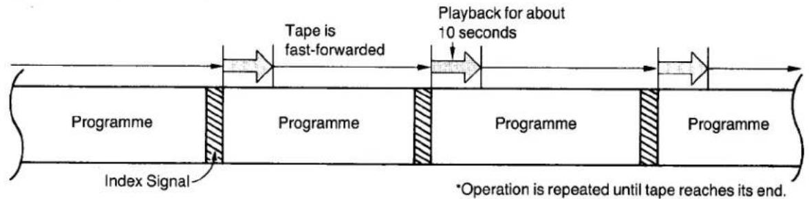
INTRO SCAN FUNCTION
How the Intro Scan Function Works...
flowchart
graph LR
    A["Tape is fast-forwarded"] --> B["Playback for about 10 seconds"]
    B --> C["Programme"]
    D["Index Signal"] --> E["Programme"]
    E --> F["Programme"]
    F --> G["Programme"]
    style A fill:#f9f,stroke:#333
    style B fill:#ccf,stroke:#333
    style C fill:#cfc,stroke:#333
    style D fill:#fcc,stroke:#333
    style E fill:#cff,stroke:#333
    style F fill:#ffc,stroke:#333
    style G fill:#fcc,stroke:#333
The Intro Scan function plays back the first 10 seconds of each programme (recorded with index signal) on a tape one after another. This is convenient for quick checking what programmes are on a tape, or to find the desired instalment of a TV series you have recorded on a tape.
Convenient Intro Scan Operation with the Remote Controller
① Insert a video cassette on which index signals are recorded.
② Put the VTR in the stop mode or the still playback mode.
3 Press the Intro Scan Button.
("S" mark will light up in the Multi-Function Display and the Intro Scan will start.)
4 When the desired scene is reached, press the Play Button.
Intro Scan Operation on the VTR
① Insert a video cassette.
(Put the VTR in the stop mode.)
② Press the Memory/Search Button twice. ("S" mark appears.)
③ Press the Fast Forward ▶▶/Cue ▶▶ Button.
(The Intro Scan starts.)
④ When the desired scene is reached, press the Play Button.
- The Intro Scan function may not be activated for the first programme recorded close to the beginning of the tape.
- During the Intro Scan, if there is a portion without any recording on the tape, the Intro Scan function will be activated at that position to play back the tape for about 10 seconds, and the Intro Scan will then continue.
- The Intro Scan function may not be activated, if the interval between programme starts is less than 5 minutes in the LP mode, or less than 2 minutes in the SP mode.
- If a portion without any recording on the tape continues for more than about 50 minutes in the SP mode, or more than about 90 minutes in the LP mode, the Intro Scan function will be cancelled and the playback will start.
BEFORE REQUESTING SERVICE
CAUTIONS
Please read these cautions before you operate this VTR.
Avoid Sudden Changes in Temperature
If the VTR is suddenly moved from a cold place to a warm place, moisture may form on the tape and inside the VTR. In this case, the Dew Indicator "d" will flash on and off and the VTR will not operate.
Humidity and Dust
Avoid places where there is high humidity or much dust, which may cause damage to internal parts.
Do Not Obstruct the Ventilation Holes
The ventilation holes prevent abnormal increase in temperature. Do not block or cover these holes. Especially avoid covering the holes with soft materials such as cloth or paper.
Keep away from High Temperature
Keep the VTR away from extreme direct heat such as direct sunlight, heating radiators, or closed automobiles.
Keep Magnets away
Never bring a magnet or magnetized object near the VTR because it will adversely affect the performance of the VTR.
No Fingers or Other Objects Inside
Touching internal parts of this VTR is dangerous, and may cause serious damage to the VTR. Do not attempt to disassemble the VTR. There are no user serviceable parts inside.
Keep Water away
Keep the VTR away from flower vases, tubs, sinks, etc. CAUTION: If liquids are spilled into the VTR, serious damage could occur. If you spill any liquid into the VTR, consult qualified service personnel.
Cleaning the VTR
Wipe the VTR with a clean, dry cloth. Never use cleaning fluid, or other chemicals. And do not use compressed air to remove dust.
Stacking
Place the VTR in a horizontal position, and do not place anything heavy on it.
Video Head Clogging
The video heads are the means by which the recorder places picture signals on the tape during recording, and reads picture signals from the tape during playback. If these heads become dirty and clogged from long use, the signals can no longer be recorded correctly, and the playback picture will be distorted accordingly. This is the case, for example, during the playback of a tape, the sound is reproduced normally, but no picture is seen, or the picture is greatly distorted. When such a symptom case occurs have the recorder checked by qualified service personnel.
If Dew Condensation Forms in the VTR
Condensation may form in the VTR if:
●The VTR is in a room where the heater has just been turned on.
●The VTR is in a room with steam or high humidity.
●The VTR is brought from cold surroundings into a well-heated room.
●The VTR is suddenly brought from cool surroundings, such as an air-conditioned room or car, to a place which is hot and humid.
When dew forms in the VTR: (Refer to page 6.)
The Dew Indicator "d" on the Multi-Function Display will flash on and off and all the function buttons are made non-operational to protect the tape and the video heads.
When the Dew Indicator flashes, wait until this indicator disappears.
- If dew condensation forms inside the VTR while the VTR On/Off Switch is off, it will turn on automatically and the Dew Indicator will flash on and off. As soon as the dew condensation has been dissolved, the VTR will turn itself off again.
NV-D80B
| Power Source: | 240 V AC 50–60 Hz | ||
| Power Consumption: | Approx. 32 watts | ||
| Video Recording System: | 2 rotary heads, helical scanning system | ||
| Tape Speed: | SP; 23.39 mm/sec.LP; 11.7 mm/sec. | ||
| Tape Format: | VHS tape | ||
| Record/Playback Time: | SP; 240 min. with NV-E240LP; 480 min. with NV-E240 | ||
| FF/REW Time: | Less than 5.5 min. with NV-E180 | ||
| VIDEO | |||
| Television System: | CCIR; 625 lines, 50 fields, PAL colour signal | ||
| Modulation System: | Luminance; FM azimuth recordingColour signal; converted subcarrier phase shift recording | ||
| Input Level: | VIDEO IN (BNC); AV; | 1.0 Vp-p,1.0 Vp-p, | 75 ohm, unbalanced75 ohm, unbalanced |
| Output Level: | VIDEO OUT (BNC);AV;RF Modulated; | 1.0 Vp-p,1.0 Vp-p,UHF channel 36 (±4), | 75 ohm, unbalanced75 ohm, unbalanced75 ohm, unbalanced |
| AUDIO | |||
| Input Level: | AUDIO IN (PHONO);AV;MICROPHONE; | -10 dB,-10 dB,-70 dB | more than 50 kohm, unbalancedmore than 10 kohm, unbalanced |
| Output Level: | AUDIO OUT (PHONO);AV;HEADPHONES; | -8 dB,-6 dB,-30 dB, | less than 1 kohm, unbalancedless than 1 kohm, unbalanced8 ohm |
| Audio Track: | 1 track (Normal-mono only), 2 channels (Hi-Fi sound-stereo) | ||
| Video Horizontal Resolution: | Colour; more than 240 lines (SP) | ||
| Signal-to-Noise Ratio: | Video; more than 43 dB (SP) | ||
| Dynamic Range: | Audio; more than 90 dB (Hi-Fi audio track) | ||
| Audio Frequency Response: | 20 Hz–20 kHz (Hi-Fi audio track) | ||
| Wow and flutter: | 0.005% Wrms/Hi-Fi | ||
| Operating Temperature: | 5°C–40°C | ||
| Operating Humidity: | 35%–80% | ||
| Weight: | 7.0 kg | ||
| Dimensions: | 430 (W)×109.5 (H)×357 (D) mm | ||
| Standard Accessories: | 1 pc. DIN-DIN Coaxial Cable1 pc. Programmable Remote Controller2 pcs. “R6” size batteries2 pcs. Stereo type Phono Cable1 pc. AC Mains Lead1 pc. Digital Scanner (with Programming Sheet)4 pcs. “R03” size batteries (for Digital Scanner)1 pc. Cable Clamper | ||
Weight and dimensions shown are approximate.
Specifications are subject to change without notice.
Matsushita Electric Trading Co., Ltd.
P.O. Box 288, Central Osaka, Japan
- Operating Instructions
- Panasonic
- CONTENTS
- IMPORTANT
- WARNING
- FOR YOUR SAFETY
- ■ DO NOT REMOVE OUTER COVER.
- ■ AC MAINS LEAD CONNECTION
- FEATURES
- Digital NR Switch
- Digital Special Effect
- 1-Month Calendar Timer
- Auto Operation
- Super OTR Function (One-Touch Timer Recording)
- HQ (High Quality) Picture System
- Lap Time Counter
- Digital Scanner
- VHS Index Search System
- Intro Scan Function
- Hi-Fi Stereo System
- Recording and Playback of "Simulcast" Sound
- Digital Still, Digital Still Advance and Digital Double Fine Slow Playback
- Programmable Remote Controller
- Hours Recording and Playback
- CONTROLS AND COMPONENTS
- Power Source for the Remote Controller
- CAUTION FOR BATTERY REPLACEMENT
- Load the batteries as follows:
- Note:
- INSTALLATION
- TUNING THE TV SET TO THE VIDEO PLAYBACK CHANNEL
- Connecting the AV Cable to the VTR
- SETTING THE TUNER IN THE VTR
- Preparation
- SETTING THE CLOCK TO THE PRESENT TIME
- For Example: Set the clock for Saturday, September 10, 1988, 12:35.
- THE VIDEO CASSETTE
- Inserting a Video Cassette (Auto Operation)
- Notes:
- Removing a Video Cassette
- PLAYBACK
- Rewind and Fast Forward
- Memory Function
- ① Normal Playback
- ② Adjustment of the HI-FI Audio Tracking
- ③ To Finish Playback
- Digital Still Playback
- ⑤ Cue Playback
- Review Playback
- PLAYBACK BY USING THE REMOTE CONTROLLER
- Digital Still Advance Playback
- Digital Double Fine Slow Playback
- Slow Tracking Control
- Double Speed Playback
- RECORDING FROM A TV BROADCAST SIGNAL
- To Finish the Recording
- If You Wish to Avoid Recording Unwanted Material
- Recording One TV Programme While Watching Another
- Tape Speed Selector
- Manual Adjustment of the Audio Recording Level
- HI-FI AUDIO SYSTEM
- Recording of Simulcast Sound
- Playback (or Monitoring during Recording)
- USING THE VTR AS A HI-FI AUDIO RECORDER
- Hi-Fi Audio Recording
- HI-FI Audio Playback
- Adjustment of the Hi-Fi Audio Tracking
- OTR Function with Immediate Start
- TIMER RECORDING
- Programming of Timer Recordings with the Remote Controller
- How to Set the Date and the Starting & Ending Times for Timer Recordings
- For Example:
- For Everyday Recording
- For Everyweek Recording
- To Confirm the Programme of a Timer Recording
- To Cancel a Timer Recording
- AUDIO DUBBING
- DIGITAL SPECIAL EFFECTS
- Digital Frame Store
- Digital Strobe
- Digital Graphic Effect
- Intro Scan Operation on the VTR
- BEFORE REQUESTING SERVICE
- CAUTIONS
- Avoid Sudden Changes in Temperature
- Humidity and Dust
- Do Not Obstruct the Ventilation Holes
- Keep away from High Temperature
- Keep Magnets away
- No Fingers or Other Objects Inside
- Keep Water away
- Cleaning the VTR
- Stacking
- Video Head Clogging
- If Dew Condensation Forms in the VTR
- Condensation may form in the VTR if:
- When dew forms in the VTR: (Refer to page 6.)
Marke : PANASONIC
Modell : NV-D80EV
Kategorie : Videorekorder