
Tracker 4 - Stativ Vanguard - Kostenlose Bedienungsanleitung
Finden Sie kostenlos die Bedienungsanleitung des Geräts Tracker 4 Vanguard als PDF.


| Produkttyp | Stativ |
| Marke | Vanguard |
| Modell | Tracker 4 |
| Maximale Höhe | 170 cm |
| Minimale Höhe | 50 cm |
| Zusammengeklappte Länge | 68 cm |
| Gewicht | 2,4 kg |
| Maximale Tragfähigkeit | 10 kg |
| Beinsegmente | 4 Stück |
| Beinverschlüsse | Drehverschlüsse |
| Material | Aluminium |
| Stativkopf | 3-Wege-Neiger mit Schnellwechselplatte |
| Nivellierung | Wasserwaage |
| Befestigungsgewinde | 1/4 Zoll |
| Spike-Füße | Abnehmbar |
| Farbe | Schwarz |
| Lieferumfang | Stativ, Stativkopf, Tragetasche, Bedienungsanleitung |
| Garantie | 2 Jahre |
| Pflegehinweise | Mit einem trockenen Tuch reinigen, nicht in Wasser eintauchen |
| Reparierbarkeit | Ersatzteile über den Hersteller erhältlich |
Häufig gestellte Fragen - Tracker 4 Vanguard
Benutzerfragen zu Tracker 4 Vanguard
0 Frage zu diesem Gerät. Beantworten Sie die, die Sie kennen, oder stellen Sie Ihre eigene.
Eine neue Frage zu diesem Gerät stellen
Laden Sie die Anleitung für Ihr Stativ kostenlos im PDF-Format! Finden Sie Ihr Handbuch Tracker 4 - Vanguard und nehmen Sie Ihr elektronisches Gerät wieder in die Hand. Auf dieser Seite sind alle Dokumente veröffentlicht, die für die Verwendung Ihres Geräts notwendig sind. Tracker 4 von der Marke Vanguard.
BEDIENUNGSANLEITUNG Tracker 4 Vanguard

natural_image
Symbolic circular icon with a white V-shaped arrow inside, no text or numbers present.VANGUARD®
PROFESSIONAL TRIPODS
User Manual

natural_image
Person using a camera on a tripod in a snowy landscape (no visible text or symbols)Elite Series
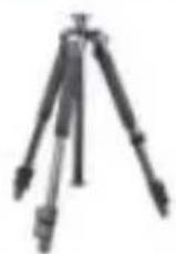
Elite L-28
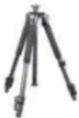
natural_image
Black tripod with tripod legs and tripod base (no text or symbols visible)Elite L-32
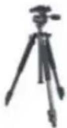
Elite S

natural_image
Silhouette of a tripod with adjustable arm and legs (no text or symbols visible)Elite I
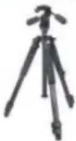
natural_image
Simple line drawing of a tripod with a tripod handle (no text or symbols)Elite 4
Tracker Series

natural_image
Simple line drawing of a tripod with tripod base and tripod top (no text or symbols)Tracker S

natural_image
Black tripod with tripod-mounted camera (no text or symbols visible)Tracker I
natural_image
Simple line drawing of a tripod with tripod handle and tripod base (no text or symbols)Tracker 2
natural_image
Simple line drawing of a tripod with tripod handle and tripod base (no text or symbols)Tracker 3

natural_image
Simple line drawing of a tripod with tripod base and tripod legs (no text or symbols)Tracker 4

Tracker B-100
natural_image
Simple line drawing of a tripod with tripod legs and tripod base (no text or symbols)Tracker B-200

natural_image
Black tripod with tripod-mounted camera (no text or symbols visible)Tracker B-300
Panhead

natural_image
Close-up of a black mechanical tool with a handle, labeled PH-50 below (no other text or symbols)
natural_image
Mechanical device with four articulated arms (no visible text or symbols)PH-55
Ballhead

SBH-100

SBH-200
SBH-300
Parts

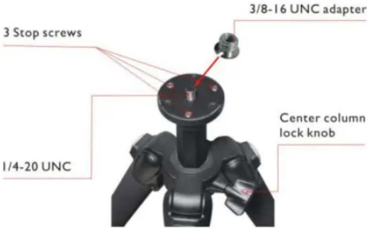
Parts

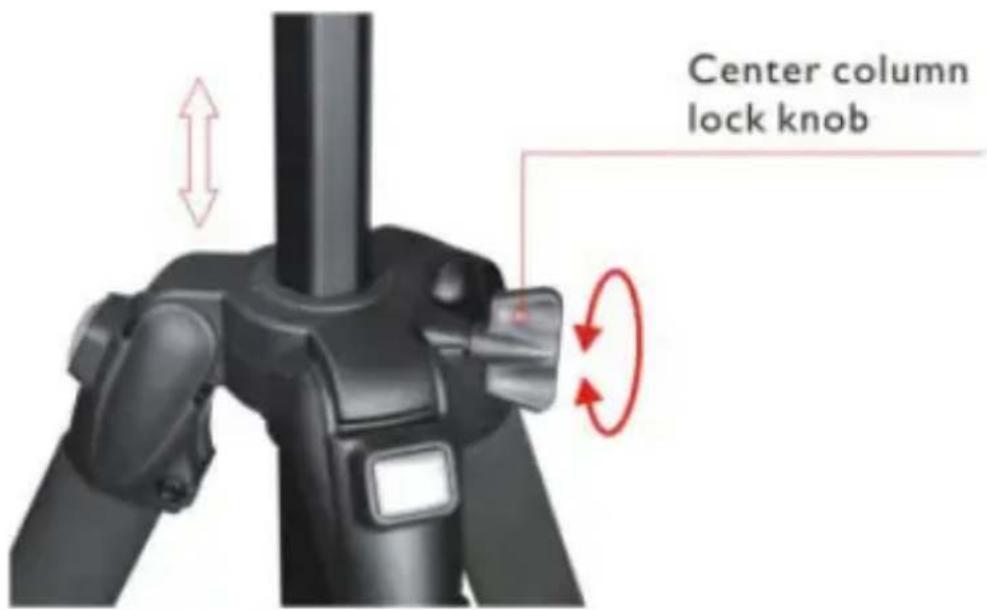
Loosen the center column lock knob and the center column can be adjusted up or down to the desired height.
• Using the low angle photo adapter

Press the two pins on the bottom of center column and pull out the adapter.

natural_image
Close-up of hands performing a medical procedure on a black object, with red arrows indicating direction (no text or symbols)
natural_image
Close-up of a black mechanical component with a red upward arrow indicating motion or force direction (no text or symbols)Push the low angle photographic adapter into the hole of canopy. Lock the center column lock knob. Attach the camera to the low angle photographic adapter to take photos.


natural_image
Black-and-white photo of a camera tripod with adjustable arms and legs (no visible text or symbols)- Macro photography

Remove the low angle photographic adapter from the center column, affix the panhead to the center column, reverse the center column by sliding it into the center hole from the bottom up, lock the center column lock knob to keep the center column in place.
This will offer the low angles needed for macro photography.

natural_image
Black tripod-mounted camera mounted on a stand with a yellow paper nearby (no visible text or symbols)Leg angles

By pressing the button the legs will pull out to 3 different angles
The leg locks are designed to hold heavy equipment

Wrench

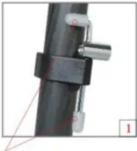
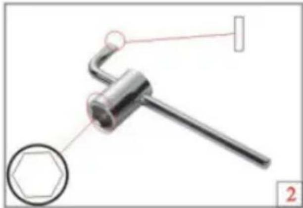
Adjust the leg lock tension by using the wrench included with the tripod.
natural_image
Close-up of a mechanical clamp or bracket with metal parts, no visible text or symbolsTake off the caps
natural_image
Mechanical tool with hexagonal base and curved handle, no visible text or symbolsMultipurpose Wrench
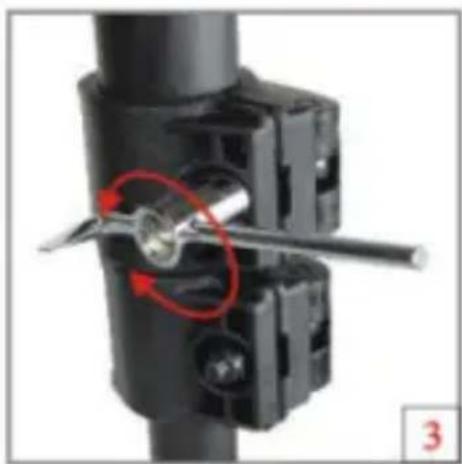
natural_image
Mechanical assembly diagram showing a tool interacting with a mechanical component (no text or symbols visible)Tighten or loosen as desired
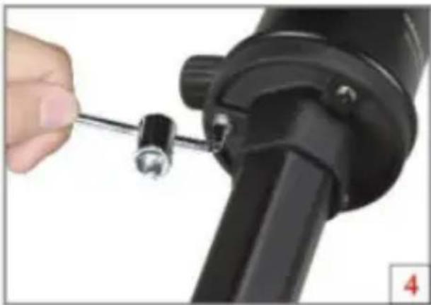
natural_image
Close-up of a hand using a screwdriver to adjust a black mechanical component (no text or symbols visible)Panhead is affixed using 3 screws
PH-50

Fluid panhead +90°\~-60° tilt for smooth control of movement
move the panhead to the desired horizontal location, then lock the knob

move the panhead to the desired vertical location, then lock the knob
move the panhead to the desired vertical location, then lock the knob
PH-55
+90°\~-30° tilt for smooth control of movement

The panhead offers full range 3-way movement on 3 axis's through the operation of 3 independent locking handles
- Removing the quick shoe
Loosen the quick shoe knob and push the secondary QS lock lever down, so pin is flush with the housing, then pull the quick shoe straight back and out.

natural_image
Close-up of a black mechanical component with a central knob and handle (no visible text or symbols)Secondary QS Lock
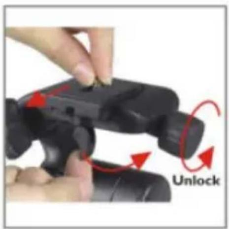
natural_image
Close-up of hands holding a black game controller with red arrows indicating unlock action (no text or symbols on device)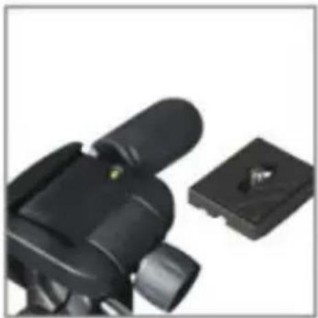
natural_image
Close-up of a black camera lens and a small square object (no text or symbols visible)- Attach the quick shoe to a camera

natural_image
Close-up of hands holding a black DSLR camera module (no visible text or symbols)
natural_image
Close-up of hands holding a black DSLR camera with a small inset showing a lens (no text or symbols visible)An extra 3/8-16 UNC quick shoe included, for medium format equipment.
Ball Head

1/4-20UNC screw
Dual bubble level
Progressive friction control knob
Indented indexed pan base
3/8-16UNC screw
Quick shoe
Secondary QS lock
Knob (Fine tuning)
Knob (Panning lock)
Ball Head user guide

Quick shoe

Secondary QS Lock


natural_image
Close-up of a black mechanical component with red directional arrows indicating movement or force (no text or symbols visible)VANGUARD ball heads feature
Strong die-casting construction, precision machined magnesium alloy housing, and an extremely hard resin ball provides incredibly smooth movements in any position.

natural_image
Mechanical device with red directional arrows indicating rotation or movement (no text or symbols visible)
natural_image
Close-up of a black industrial device with a red curved arrow indicating rotation (no visible text or symbols)Features a single locking knob for 360-degree pan and a groove for 90-degree tilt movements.
Self-damping fine tuning knob

Gently clamps the ball while still letting you easily move your camera into any position. The locking mechanism secures even your heaviest equipment in under a half a turn.

natural_image
Black VANGUARD 38H-26B camera head with adjustable arm and adjustment knob (no text or symbols on body)• Adjustable center of gravity

natural_image
Close-up of a DSLR camera with visible lens and grip (no text or symbols)
natural_image
Close-up of a black mechanical component with red directional arrows indicating movement or force (no text or symbols visible)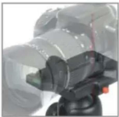
natural_image
Close-up of a DSLR camera with lens and control lever (no visible text or symbols)Screw can be adjusted forward or back to offer the correct center of gravity for the equipment.
Ballhead body, platform, and plate can be separated

natural_image
Black industrial camera module components including a cylindrical head, connector housing, and green indicator lights (no text or symbols visible)The platform can be attached to the ballhead body

natural_image
Close-up of a hand using a black tool to adjust a black game controller (no text or symbols visible)The platform can be attached to the ballhead with a screw
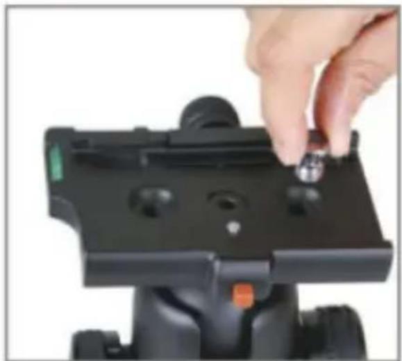
Screw hole to store the camera screw
natural_image
Close-up of a hand adjusting a black camera mount base with a small metallic clip (no text or symbols visible)- Attaching the ball head to the tripod

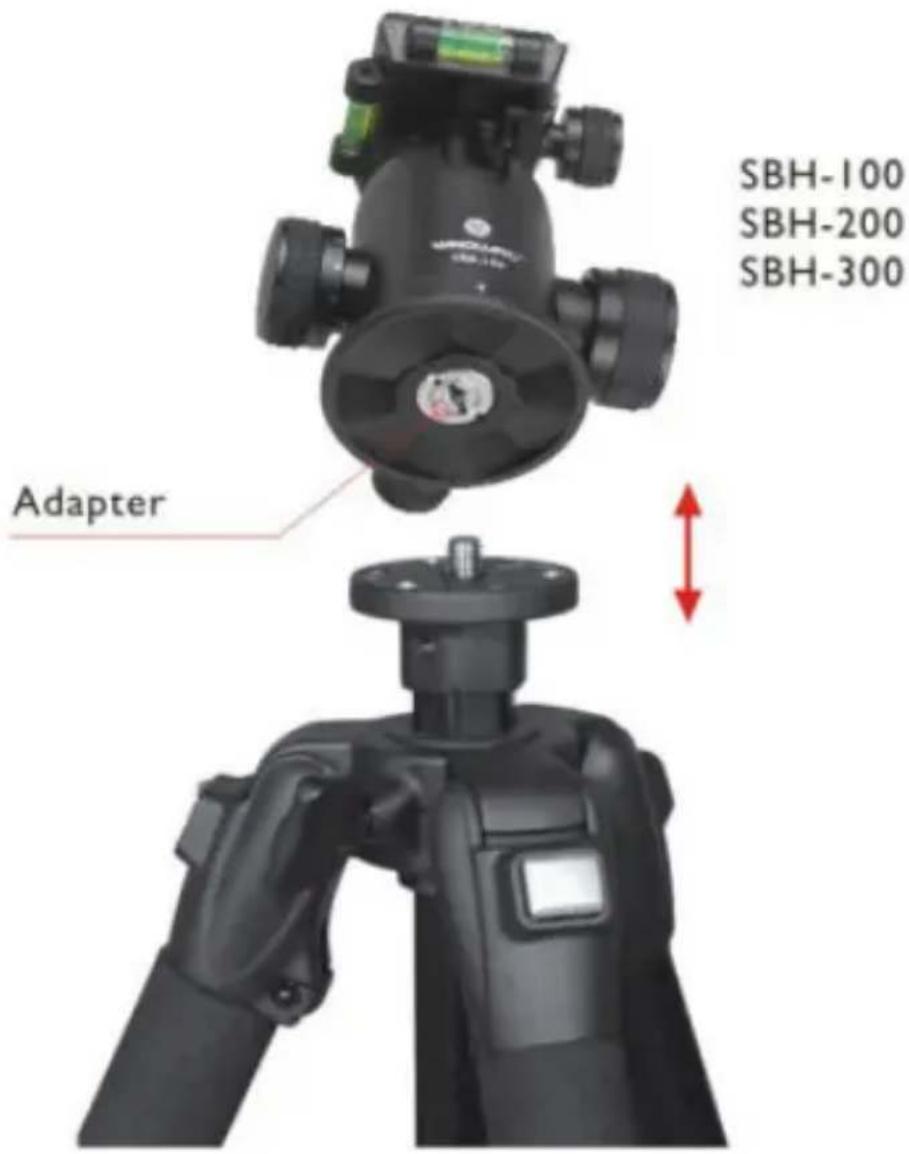
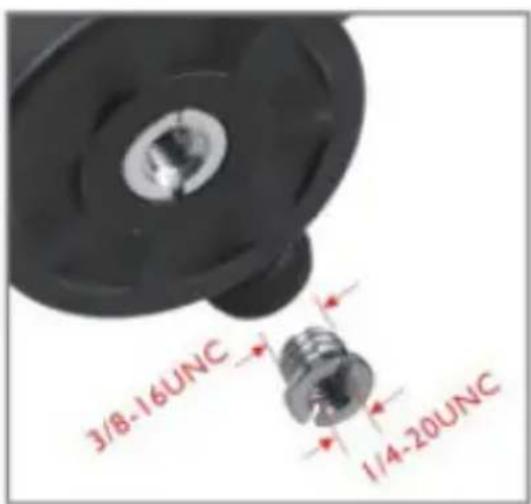

natural_image
Close-up of a hand holding a small metallic component with a flanged base (no text or symbols visible)- Plate adaptors

PQ-45
* Plate adaptors
* PF-2 with QS-45
* 90mm length QS
*Adjustable screw

natural_image
Black mechanical component with adjustment knobs and a green indicator button (no text or symbols visible)
natural_image
Black mechanical component with two circular ports and a red orange terminal (no text or symbols visible)
PQ-46
* Plate adaptors
* PF-2 with QS-46
* 140mm length QS
*Adjustable screw
QS-46

natural_image
Black rectangular electronic component with metallic pins and a central slot (no text or symbols visible)* Quick shoe with 1/4" & 3/8" camera screw & pin
* 140mm length QS
*Adjustable screw
AT-6 adapter
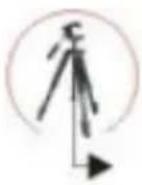
Converts the camera screw from 3/8" to 1/4".
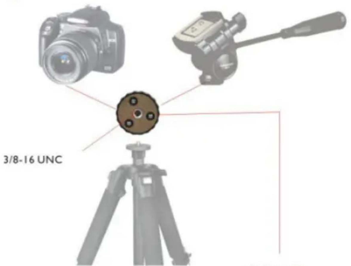
1/4-20 UNC

natural_image
Technical diagram showing a mechanical component with a circular base and internal spring assembly (no text or labels)3/8-16 UNC
Multi-Mount 6
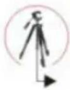

natural_image
Diagram of a tripod-mounted optical instrument with two cameras mounted on top, showing alignment and adjustment arrows (no text or symbols)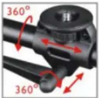
Camera can be adjusted for 360^ rotation on a horizontal plane.
natural_image
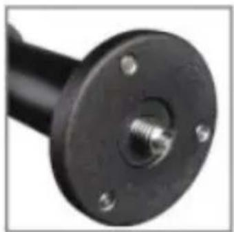
Close-up of a black mechanical flange with bolt holes and a threaded end (no text or symbols visible)3/8" Camera screw

natural_image
Close-up of a black mechanical component with a circular head and two protruding rods (no visible text or symbols)Center connects with 3/8" tripod screw
natural_image
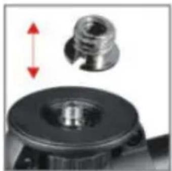
Close-up of a mechanical component with a metallic threaded part and a black circular base, showing a red double-headed arrow indicating vertical displacement (no text or symbols)From 1/4"change to 3/8" for medium format equipment.
www.vanguardworld.com


- VANGUARD®
- PROFESSIONAL TRIPODS
- Elite Series
- Tracker Series
- Panhead
- Ballhead
- Parts
- • Using the low angle photo adapter
- - Macro photography
- Leg angles
- Wrench
- PH-50
- PH-55
- - Removing the quick shoe
- - Attach the quick shoe to a camera
- Ball Head
- Ball Head user guide
- VANGUARD ball heads feature
- Self-damping fine tuning knob
- • Adjustable center of gravity
- - Attaching the ball head to the tripod
- - Plate adaptors
- PQ-45
- PQ-46
- QS-46
- AT-6 adapter
- Multi-Mount 6
Marke : Vanguard
Modell : Tracker 4
Kategorie : Stativ