
WV-SFR531 - Overvågningskamera PANASONIC - Gratis brugsanvisning og manual
Find enhedens vejledning gratis WV-SFR531 PANASONIC i PDF-format.


Brugerspørgsmål om WV-SFR531 PANASONIC
0 spørgsmål om dette apparat. Besvar dem du kender, eller stil dit eget.
Stil et nyt spørgsmål om dette apparat
Download vejledningen til din Overvågningskamera i PDF-format gratis! Find din vejledning WV-SFR531 - PANASONIC og tag din elektroniske enhed tilbage i hånden. På denne side er alle dokumenter nødvendige for brugen af din enhed offentliggjort. WV-SFR531 af mærket PANASONIC.
BRUGSANVISNING WV-SFR531 PANASONIC
Panasonic®
Installation Guide
Included Installation Instructions
Network Camera
Model No. WV-SFR531/WV-SFN531
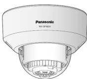
(This illustration represents WV-SFN531.)

- This manual describes the installation procedures, network camera installation, cable connections, and the angle of view adjustment.
• Before reading this manual, be s
- This manual describes how to install the network camera using model WV-SFN531 as an example.
For U.S. and Canada
Panasonic System Communications
Company of North America,
Unit of Panasonic Corporation of North America
of North America
For customer support, call 1.800
Two Riverfront Plaza, Newark, NJ 07102-5490
Panasonic Canada Inc
5770 Ambler Drive, Mississauga.
Ontario, L4W 2T3 Canada
(905)624-5010 www.panasonic
© Pennsylvania System Networks Co., Ltd. 2015
For Europe and other countries:
Panasonic Corporation
http://www.panasonic.com
• • •
Panasonic Syste
Fukuoka, Japan

Panasonic Canada Inc.
5770 Ambler Drive, Mississauga
Ontario, L4W 2T3 Canada (005)634 5010
(803)624-3010 www.panasonic.ca
© Pennsylvania System Networks Co., Ltd. 2015
PGQX1909ZA fles0615-0 Printed in China
Parts and functions
The component names of the camera are as follows. Refer to the illustration when installing or adjusting the camera.
adjusting the camera.
Auto focus (AF) button
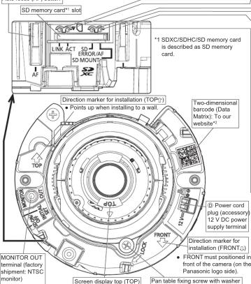
*2 Depending on the scanning application used, the Data Matrix may not be able to be read
correctly. In this case, access the site by directly entering the following URL: http://www.nescartis.com/ (http://www.nescartis.com)
http://security.panasonic.com/pss/security/support/qr_sp_select.html
Standard accessories
Important Information .... 1 pc. CD-ROM*1 .... 1 pc. Installation Guide (this document) .... 1 set Code label*2 .... 1 pc. Warranty card .... 1 set
*1 The CD-ROM contains the operating instructions and different kinds of tool software programs.
*2 This label may be required for network management. The network administrator shall retain the code label.
The following parts are used during installation procedures.
⑧ Attachment plate 1 pc. ⑪ Power cord plug*3 1 pc.
⑧ Bit (Hex wrench, screw) ⑨ External I/O terminal plug*3 1 pc size S 25 mm (1/4 inches) T10) 1 pc (① MONITOR OUT acquisition plug) 4 pc
size 0.35 mm (114 inches) 1 pc. © MONITOR OUT conversion plug ..... 1 pc. © Template A (for the attachment plate) 1 sheet. © Auxiliary handle 1 pc
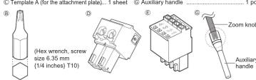
*3 The external I/O terminal plug and power cord plug are attached to the camera.
Azimuth adjustment ring
Ⓐ Attachment plate
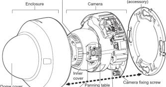
Tilting table (E) External I/O terminal plug (accessory)
LINK Indicator
- When the camera is able to communicate with the connected device Lights orange
ACT indicator
- When data is being sent via the network camera Blinks green (accessing)
SD ERROR/AF indicator
- When AF (Auto Focus) operation is being executed Blinks red (1 time/second)
- When the set is being started
- When an SD memory card is recognized normally - When an abnormality is detected in the SD memory card
- When an abnormality is detected in the SD memory card or the SD memory card slot is not used after
of the CD memory card slot is not the camera has started
SD MOUNT indicator
SD MOUNT Indicator - When an SD memor
- When an DB memory card is inserted and could be recognized Lights off
- When data can be saved after the SD memory card is Lights off → Lights green
inserted and the SD ON/OFF button is pressed
(less than 1 second)
- When data can be saved to the SD memory card
- When the SD memory card is removed after holding down the SD ON/OFF button (about 2 seconds) Lights green → Blinks green → Lights off (recording)
down the SD ON/OFF button (about 2 seconds) Lights off (recording) Lights green → Lights off
(Lights given + Lights (waiting for recording))
- When data cannot be saved to the SD memory card because
an abnormality was detected or the SD memory card is
configured not to be used
Note:
- Lighting/blinking LED can be turned off with the software settings at any time. (The initial
state is lighting or blinking.) Set the LED to be solid off if necessary, depending on the
installation conditions. (E- Operating instructions included in the CD-ROM)
SD ON/OFF button
① When the SD ON/OFF button is pressed (less than 1 second), the SD MOUNT indicator lights
① When the SD ON/OFF button is pressed (less than 1 second), the SD MOONT indicator lights up in green and data can be saved to the SD memory card* ^1 .
② When the SD ON/OFF button is held down (about 2 seconds), the SD MOUNT indicator lights
off and the SD memory card can be removed.
INITIAL SET button (Initializing / NTSC ◦ PAL switch button)
• How to initialize the camera
Follow the steps below to initialize the network camera
① Turn off the power of the camera. When using a PoE hub, disconnect the LAN cable from the camera.
When using an external power supply, disconnect the power cable connector of the camera.
② Turn on the power of the camera while holding down the INITIAL SET button, and keep the INITIAL SET button hold down till the SD MOUNT indicator in lit in omen (more than 10 seconds). In about 2 minutes after looking
held down on the SD MOONT Indicator is it in green (more than 10 seconds). In about 2 minutes after releasing the INITIAL SET button, the camera will start up and the settings including the network settings will be initialized.
IMPORTANT
IMPORTANT:
- When the camera is initialized, the settings including the network settings will be initialized. Note that the CRT low (PCI) operation level used for the HTTPS protocol will not be initialized.
Note that the CRT key (SSL encryption key) used for the HTTPS protocol will not be initialized.
- Before initializing the settings, it is recommended to write down the settings in advance. - Do not turn off the power of the camera during the process of initialization. Otherwise, it
- Do not turn on the power of the camera during may fail to initialize and may cause malfunction.
- When the INITIAL SET button (i.e. the initializing button) is pressed (less than 1 second) to
- Which the INITIAL SET button (i.e. the initializing button) is pressed (less than 1 second) to switch the output signal of the MONITOR OUT terminal (NTSC≡PAL output), the MONITOR
OUT terminal can be switched for the NTSC monitor/PAL monitor.
Making connections
Turn off each system's power supply before making a connection. Before making connections, prepare the required peripheral devices and cables.
Connect the power cable
Coulion
• A READILY ACCESSIBLE DISCONNECT DEVICE SHALL BE INCORPORATED
TO THE EQUIPMENT POWERED BY 12 V DC POWER SUPPLY.
- ONLY CONNECT 12 V DC CLASS 2 POWER SUPPLY (UL 1310/CSA 223) or
LIMITED POWER SOURCE (IEC/EN/UL/CSA 60950-1)
Connect the output cable to the Ⓓ power cord plug (accessory).
① Loosen the screw of the power cord plug (accessory), strip 3 mm to 7 mm {1/8 inches to
9/32 inches) from the end of the wire, twist the stripped part of the wire sufficiently to avoid
short circuit, and then connect the output cable to the power cord plug (accessory).
② Tighten the screw of the power cord plug. (Recommended tightening torque: 0.34 N·m (0.25 lbf·ft))
3.25 187 N _77
Note:
- Check whether the stripped part of the wire is not exposed and is securely connected.
- When connecting an external power supply to the camera, use the AWG16 to AWG24
single-wired or stranded wired cables.
IMPORTANT:
- The 12 V DC power supply shall be insulated from the commercial AC power
- Be sure to use the Ⓓ power cord plug (accessory) provided with this product
- Be sure to fully insert the Ⓓ power cord plug (accessory) into the 12 V DC power
supply terminal. Otherwise, it may damage the camera or cause malfunction. - When installing the camera, make sure that excessive force is not applied to
power cable. - Be sure to use an AC adaptor compliant with the Specifications (written in the indication label on the bottom side of this unit) regarding power reserves and power consumption.
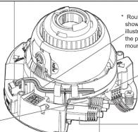
* Route the power cable as
shown in the following illustration, and do not elie
illustration, and do not clip the power cable when
the power cable when mounting the enclosure.
Connect an external amplifier-embedded speaker to the audio output termina
Connect a stereo mini plug (ø3.5 mm)
- Output impedance : Approx. 600 Ω (unbalanced)
- Recommended cable length: Less than 10 m (32.6 feet)
- Output level: -30 dBV
2.5p 0.176
IMPORTANT:
- Connect/disconnect the audio cables and turn on the power of the camera after turning
off the power of the audio output devices. Otherwise, loud noise may be heard from the applications.
the speaker. • Make sure that the stereo mini plug is con - Make sure that the stereo mini plug is connected. audio may not be heard
When connecting a monaural speaker with amplifier, use a locally procured conversion
cable (mono-stereo).
Connect an microphone to the microphone/line input terminal
Connect a stereo mini plug (ø3.5 mm)
- Input impedance: Approx. 2 kΩ (unbalanced)
- Recommended cable length: Less than 1 m {3.28 feet} (for microphone input)
Less than 10 m {32.8 feet} (for line input)
- Recommended microphone: P
- Supply voltage: 2.5 V +0.5 V
- Recommended sensitivity of microphone: -48 dB ± 3 dB (0 dB=1 V/Pa, 1 kHz)
- Input level for the line input: Approx. -10 dBV
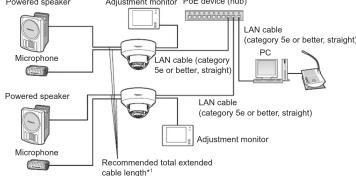
When connecting to a network using a PoE hub
Before starting the installation, check the entire system configuration. The following illustration
gives a wiring example of how to connect the camera to the network
Powered speaker Adjustment monitor PoE device (hub)
flowchart
graph TD
    A["Microphone"] --> B["Powered speaker"]
    C["Microphone"] --> D["Recommended total extended cable length*"]
    B --> E["LAN cable (category 5e or better, straight)"]
    D --> F["LAN cable (category 5e or better, straight)"]
    E --> G["PC"]
    F --> H["Adjustment monitor"]
    G --> I["LAN cable (category 5e or better, straight)"]
Connect the alarm input/output cable
Connect the cables of external devices to the Ⓔ External I/O terminal plug (accessory).
① When connecting an external device, strip 8 mm - 9 mm (5/16 inches - 11/32 inches) of the
outer jacket of the cable and twist the cable core to prevent the short
Specification of cable (wire): AwG20 - AwG26, Single core, twisted
② Push down the button of the desired terminal on the external I/O terminal plug with a ball
① Push down the button of the desired terminal on the external I/O terminal play with a ball point pan, and release the button when the cable of the external device is fully inserted.
point pen, and release the button when the cable of the external device is fully inserted into the terminal hole.
into the terminal notes.
Note:
- Check whether the stripped part of the wire is not exposed and is securely connected.
• ALARM IN1(DAY/NIGHT IN), ALARM IN2, ALARM IN3
Input specification : No-voltage make contact input (4 V - 5 V DC, internally pulled up)
OFF : Open or 4 V - 5 V DC
ON : Make contact with GND (required drive current: 1 mA or more)
• ALARM OUT AUX OUT
Output specification: Open collector output (maximum applied voltage: 20 V DC)
Open : 4 V - 5 V DC by internal pull-up
Close : Output voltage 1 V DC or less (maximum drive current: 50 mA)
* The default of EXT I/O terminals is "Off".
Button GND
ALARM IN3, AUX OUT (Alarm input terminal 3, AUX output terminal)
ALARM IN2. ALARM OUT (Alarm input terminal 2. Alarm output terminal)
(1) AUM-40, AUM-40, AUM-40, AUM-40, AUM-40, AUM-40, AUM-40, AUM-40, AUM-40, AUM-40, AUM-40, AUM-40, AUM-40, AUM-40, AUM-40, AUM-40, AUM-40, AUM-
ALARM IN1, DAY/NIGHT IN
(Alarm input terminal 1, DAY/NIGHT input terminal)
① External I/O terminal plug (accessory)
IMPORTANT
- Do not connect 2 wires or more directly to a terminal. When it is necessary to connect
2 or more wires, use a splitter.
• Install external devices so that they do not exceed the rating of the network camera - When using the EXT I/O terminals as the output terminals, ensure they do not
cause signal collision with external signals.
Note:
- Off, input, and output of the external I/O terminal 2 and 3 can be switched by con-
figuring the setting. Refer to the operating instructions on the provided CD-ROM for
further information about the EXT I/O terminal 2 and
("Off", "Alarm input", "Alarm output" or "AUX output")
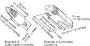
Connect a LAN cable to the network connector
Use a LAN cable (category 5e or better, 8 pins, straight)
IMPORTANT:
• Use all 4 pairs (8 pins) of the LAN cable.
• The maximum cable length is 100 m (328 feet)
- Make sure that the PoE device in use is compliant with IEEE802.3af standard.
- When connecting both the 12 V DC power supply and the PoE device for power
supply, 12 V DC will be used for power supply. If a 13 V DC power supply and a ReE hub or
In a 12 V DC power supply and a PoE hub of router are used at the same time, network connections may not be possible. In this case, disable the PoE settings
Refer to the operating instructions of the PoE hub or router in use.
* In the situation where a 12 V DC power supply and a PoE hub or router are used at
the same time and the 12 V DC power supply is then disconnected, the power
supply is stopped and the camera will restart.
- When the LAN cable is disconnected once, reconnect the cable after around 2 seconds. When the cable is quickly connected, the power may not be sure
2 seconds. When the cable is quickly reconnected, the power may not be supplied from the RoE device.
from the PE device.
LAN cable (category 5e or better, straight)
Use a LAN cable (category 5e or better, cross) when directly connecting the camera to a PC.
*1 Recommended cable length from the speaker : less than 10 m (32.8 feet)
recommended cable length from the microphone : less than 1 m (3.28 feet)
IMPORTANT:
- The adjustment monitor is used for checking the adjustment of the angular field of
view when installing the camera or when servicing. It is not provided for recording/
monitoring use. - Depending on the monitor, some characters (camera title, preset ID, etc.) may not be found on the camera.
be displayed on the screen. - Use a switching hub or a router which is compliant with 10BASE-1/100BASE-TX.
- If a RoE hub is not used, each regularly cannot be requested to a 12VDC.
- If a POE hub is not used, each network camera must be connected to a 12 V DC power supply.
• When using 1 - When using 12 V DC, power supply from a PE hub of reader is not required
The Ground Truth image displays a single, solid horizontal line. According to Rule 2 (UNDERSCORE & LINE RULES), this is a stylistic or background line, not a placeholder underscore. Therefore, the OCR result must ignore it and output nothing or only meaningful text. The provided OCR content is "____", which consists of four underscores. This is an incorrect interpretation of the line as a placeholder, violating the rule that stylistic lines must be ignored. The OCR has hallucinated underscores where none should exist based on the GT's visual context. Hence, the OCR result is inconsistent with the Ground Truth.
[Non-Text]
[Non-Text]
[Non-Text]
[Non-Text]
[Non-Text]
[Non-Text]
[EMPTY]
(1) AD = BD = 1
[Non-Text]
[Non-Text]
[Non-Text]
[Non-Text]
[Non-Text]
[Non-Text]
[Non-Text]
[Non-Text]
[Non-Text]
[Non-Text]
[Non-Text]
[Non-Text]
[Non-Text]
[Non-Text]
[Non-Text]
[Non-Text]
[Non-Text]
[Non-Text]
[Non-Text]
[Non-Text]
[Non-Text]
[Non-Text]
[Non-Text]
[Non-Text]
[Non-Text]
[Non-Text]
[Non-Text]
[Non-Text]
[Non-Text]
[Non-Text]
[Non-Text]
[Non-Text]
[Non-Text]
[Non-Text]
[Non-Text]
[Non-Text]
[Non-Text]
[Non-Text]
[Non-Text]
[Non-Text]
[Non-Text]
[Non-Text]
[Non-Text]
[Non-Text]
[Non-Text]
[Non-Text]
[Non-Text]
| Step1 Preparations | Step2 Fixing the attachment plate | Step3 Mount the camera to the attachment plate | Step4 Adjustment | Step5 Configure the network settings |
Step1 Preparations
There are 4 methods to install the camera to a ceiling or wall as described below. Prepare the
required parts for each installation method before starting the installation. The following are the
requirements for the various installation methods.
Installation method
(1) Mount the camera on the two-gang junction box using
the 6 attachment plate (accessory).
(2) Directly mount the camera onto the ceiling or wall us-
ing the attachment plate (when wiring can be installed
in the ceiling or wall).
(3) Mount the camera in the ceiling using WV-Q174B ceil-
ing mount brackets (approx. 280 g (0.62 lbs)).*1
(4) When mounting the camera on an insufficient strong
ceiling using the WV-Q105A ceiling mount brackets
(approximately 150 g (0.33 lbs))*
*1 For information on mounting the camera using (3) WV-Q174B or (4) WV-Q105A, refer to
the Instruction Manual provided with the (3) WV-Q174B or (4) WV-Q105A.
*2 Make sure that the installed ceiling can support more than 5 times of the weight of the
camera, the attachment plate and the anchor bolt.
IMPORTANT:
• Procure 4 screws (M4) to secure the 5 attachment plate (accessory) to a ceiling or a
wall.
• The minimum required pull-out capacity of a single screw or anchor bolt is 196 N
(44 bf) or more when mounting with the installation method (1) and (2) above.
• When mounting the camera on a concrete ceiling, use an AY plug bolt (M4) for securing
(Recommended tightening torque: 1.6 m N (1.18 lbf ft))
• The minimum required pull-out capacity of a single screw or anchor bolt is 196 N
(44 bf) or more when mounting with the installation method (1) and (2) above.
• When mounting the camera on a concrete ceiling, use an AY plug bolt (M4) for securing
(Recommended tightening torque: 1.6 m N (1.18 lbf ft))
• The minimum required pull-out capacity of a single screw or anchor ball is 196 N
(44 bf) or more when mounting with the installation method (1) and (2) above.
• When mounting the camera on a concrete ceiling, use an AY plug bolt (M4) for securing
(Recommended tightening torque: 1.6 m N (1.18 lbf ft))
• The minimum required pull-out capacity of a single screw or anchor ball is 196 N
(44 bf) or no more when mounting with the installation method (1) and (2) above.
• When mounting the camera on a concrete ceiling, use an AY plug bolt (M4) for securing
(Recommended tightening torque: 1.6 m N (1.18 lbf ft))
• The minimum required pull-out capacity of a single screw or anchor ball is 196 N
(44 bf) or no more when mounting with the installation method (1) and (3) above.
• When mounting the camera on an insufficient strong
ceiling using the WV-Q105A ceiling mount brackets
(approximately 150 g (0.33 lbs))*
*1 For information on mounting the camera using (3) WV-Q174B or (4) WV-Q105A, refer to
the Instruction Manual provided with the (3) WV-Q174B or (4) WV-Q105A.
*2Make sure that the installed ceiling can support more than 5 times of the weight of the
camera, the attachment plate and the anchor bolt.
IMPORTANT:
• Procure 4 screws (M4) to secure the 5 attachment plate (accessory) to a ceiling or a
wall.
• The minimum required pull-out capacity of a single screw or anchor bolt is 196 N
(44 bf) or more when mounting with the installation method (1) and (2).above.
• When mounting the camera on a concrete ceiling, use an AY plug bolt (M4) for securing
(Recommended tightening torque: 1.6 m N (1.18 lbf ft))
• The minimum required pull-out capacity of a single screw or anchor ball is 196 N
(44 bf) or no more when mounting with the installation method (1) and (3) above.
• When mounting the camera on a concrete ceiling, use an AY plug bolt (M4) for securing
(Recommended tightening torque: 1.6 m N (1.18 lbf ft))
• The minimum required pull-out capacity of a single screw or anchor ball is 196 N
(44 bf) or no more when mounting with the installation method (1) and (3) above.
• If a ceiling board such as plaster board is too weak to support the total weight, the
area shall be sufficiently reinforced.
Configure the network settings
Step3 Mount the camera to the attachment plate Step5
① Loosen 2 enclosure fixing screws
of the enclosure with the 8 bit (Hex
wrench, screw size 6.35 mm (1/4
inches) T10) (accessory), and
the enclosure from the camera.
• Remove the 3 power cord plug
(accessory) and the 6 external I/O
terminal plug (accessory) attached to the
camera.
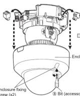 Do not remove the auxiliary wire.
• The enclosure is fixed only with enclosure
fixing screws. Please be careful about
the handling when you wish to remove.
• Using the side cable access hole
When installing the camera directly on the
ceiling or wall with cables exposed, or when
mounting the camera using the ceiling mount
brachte WV-Q174B (option), cut out a portion of
the dome cover to open a cable access hole.
IMPORTANT:
• To prevent injuries and protect the
cables, finish the side cable access hole
with a file to avoid sharp edges.
Configure the network settings
② Secure the camera by tightening the camera fixing screws.
IMPORTANT:
• Be sure to tighten the camera fixing screw.
Failure to observe this may cause camera trouble
due to camera falling. (Recommended tightening
torque: 0.78 N m (0.58 lbf ft))
Do not remove the auxiliary wire.
• The enclosure is fixed only with enclosure
fixing screws. Please be careful about
the handling when you wish to remove.
• Using the side cable access hole
When installing the camera directly on the
ceiling or wall with cables exposed, or when
mounting the camera using the ceiling mount
brachte WV-Q174B (option), cut out a portion of
the dome cover to open a cable access hole.
IMPORTANT:
• To prevent injuries and protect the
cables, finish the side cable access hole
with a file to avoid sharp edges.
Configure the network settings
② Secure the camera by tightening the camera fixing screws.
IMPORTANT:
• Be sure to tighten the camera fixing screw.
Failure to observe this may cause camera trouble
due to camera falling. (Recommended tightening
torque: 0.78 N m (0.58 lbf ft))
Loosen the cross-head side of tilt table fixing screw (onone side), and incline the tilt table while keeping the TOP. TOP mark Cross-head side of tilt table fixing screw (opposite side of the camera) Press both sides at the same line Inner cover Camera fixing screw After cables have been connected to the camera, align the 3'PEN mark of the camera side panel with the tab of the attachment plate, insert 2 attachment mounting screws into the attachment plate, and rotate the camera by approximately 15°. The LOCK mark is moved to the tab position of the attachment plate and the camera is temporarily secured. • The fixing angle of the camera can be rotated in 90° increments. Tab of the inner cover Inner cover NOTE: • Press the PUSH mark, release the four tabs of the inner cover from the tilt table, and remove the inner cover. |
| Step4 Adjustment | |
1 Tum on power for the camera by either conned-
ing a LAN cable or a 12 V DC power cable.
2 Connect their: MONITOR OUT conversion plug
(accessory) to the MONITOR OUT terminal of the
camera, and then connected the monitor for adjust-
ment with a RCA pin cable (locally procured).
3 Insert an SD memory card into the slot, if
necessary.
• Insert the SD memory card with its label
folding.
• For information about performing the SD
memory card setting, refer to the operating
instructions (included in the CD-ROM).
5 MONITOR OUT conversion
plug (accessory)
MONITOR OUT terminal
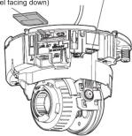 | Loosen the pan table fixing screw, and adjust the angle of the camera with the tilt table, pan table, and azimuth adjustment ring. Horizontal (PAN) angle: +120° (Right) to -240° (Left) Vertical (TILT) angle: ±65° 5 Tighten the cross-head side of tilt table fixing screw (on one side) and the pan table fixing screw, for the camera. (Recommended tightening torque: 0.59 N m (0.44 bf ft)) Tilt table fixing screw Tiling table WY6D Pan ta screw si ce pe Ver Note: • Depending on the adjustable range or the optical zoom, it must be noted that the shadow of the enclosure may be projected. • When mounting the camera on a wall, adjust the tilt angle so that the TOP mark above the lens always comes to the top side. • When mounting the camera on a wall, rotate the pan table by 180° to the left and rotate the tilt table till the TOP mark above the lens always comes to the top side. • When adjusting the viewing angle for camera mounted to ceilings, the enclosure and install auxiliary wire may be displayed on the screen depending on the direction the camera is facing. Move the enclosure and installation auxiliary wire so that they are not displayed on the screen. • Remove the camera using the reverse order of the installation procedures. |
| IMPORTANT • Settily tighten all the enclosure fixing screws (x2) of enclosure. Otherwise, the enclos dropping may result in injury. (Recommended tightening torque: 0.59 N m (0.44 bf ft)) • After complete installation, remove the cover film from the dome cover. • Delete may cause the unit restalled enclosure. In this case, perform the auto focus function from the setup menu. • Remove the camera using the reverse order of the installation procedures. | |
The installation tasks are explained using 5 steps.
| Step1Preparations | → | Step2Fixing the attachment plate | → | Step3Mount the attachment |
Step1 Preparations
| Installation method | Recommended screw | Minimum pull-out strength (per 1 pc.) |
| (1) Mount the camera on the two-gang junction box using the 3/4 attachment plate (accessory). | M4 screws x 4 | '96 N (44 bf) |
| (2) Directly mount the camera onto the ceiling or wall using the attachment plate (when wiring can be installed in the ceiling or wall). | M4 screws x 4 | '96 N (44 bf) |
| (3) Mount the camera in the ceiling using WV-0174B ceiling mount brackets (approx. 280 g (0.62 lbs)).*1 | — | There is sufficient strength in the ceiling |
| (4) When mounting the camera on an insufficiently strong ceiling using the WV-0105A ceiling mount brackets (approximately 150 g (0.33 lbs))*1 | anchor bolts x 2* | 2 |
| *1 For information on mounting the camera using (3) WV-0174B or (4) WV-0105A, refer to the Instruction Manual provided with the (3) WV-0174B or (4) WV-0105A.*2 Make sure that the installed ceiling can support more than 5 times of the weight of the camera, the attachment plate and the anchor bolt. | ||
| IMPORTANT* | ||
| • Procreate 4 screws (M4) to secure the 4 attachment plate (accessory) to a ceiling or a well. | ||
| • The minimum required pull-out capacity of a single screw or anchor bolt is 196 N (44 bf) or more when mounting with the installation method (1) and (2) above. | ||
| • When mounting the camera on a concrete ceiling, use an AV plug bolt (M4) for securing (Recommended tightening torque: 1.0 N m (1.18 bf ft)). | ||
| • Select screws according to the material of the ceiling that the camera will be mounted to. In this case, wood screws and nails should not be used. | ||
| • If a ceiling board such as the mounting board is too weak to support the total weight, the area shall be sufficiently reinforced. | ||
(1) Using a two-gang junction box
(2) Using the Attachment plate (accessory)
- If the mounting direction of the camera has already been determined
Align the FRONT direction (the direction of FRONT marker on the camera that indicates the installation direction and the following: 3.50, 1.20, 0.80)
installation direction when installing the camera) of (c) template A (accessory) with the desired direction, and drill through a 25.4 mm (1 inch) diameter hole.
If the mounting direction of the camera is not determined yet or if you want to change the
direction of the camera after it has been installed
If you want to be able to change the direction of the camera, drill through a 75 mm (2-7/8 inches) diam hole in the center. By doing so you can adjust the mounting direction of the camera in 90° increments.
Configuring the camera so that it can be accessed from a PC
The following are descriptions for when the camera with default settings is configured. If you are using fire-wall software on your PC, the Setup Program may not be able to find any cameras on your network.
Wall software on your PC, the setup program may not be done to find any camera on your network. Configure the setting of the camera after temporarily invalidating the firewall software. Contact the network
administrator or your Internet service provider for information about configuring the settings of the network.
insert the provided CD-ROM into the CD-ROM drive of your PC.
- The License Agreement will be displayed. Read the Agreement and choose "I accept
the term in the license agreement", and click [OK].
- The launcher window will be displayed. If the la click the "CDLauncher.exe" file on the CD-ROM.
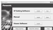

- Refer to "Using the CD-ROM" in the operating instructions on the provided
CD-ROM for further information about CDLauncher.

Click the [Run] button next to [IP Setting Software].
Panasonic IP Setting] screen will be displayed. When a camera is found, information
bout it, such as its MAC address and IP address, is displayed.
Select the camera you want to configure, and click [Access Camera].
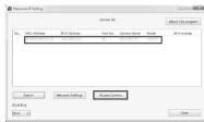

- When cameras are displayed in [Panasonic IP Setting] screen, click the cam-
era with same MAC address as the MAC address printed on the camera that
you want to configure.
④ If the installation screen of the viewer software "Network Camera View 4S" is displayed,
follow the instructions of the wizard to start the installation. (The viewer software is installed from the camera.)

The "Live" page will be displayed.
you cannot install the viewer software "Network Camera View 4S" or if images are not
isplayed, click the [install] button next to [viewer Software] on the launcher window to stall the software.
Perform the [Time
- Perform the [Time & date] settings in the Setup - Basic page before using the camera

- When no image is displayed on the "Live" page, refer to the Troubleshooting in
the operating instructions on the provided CD-ROM.
- It is possible to enhance the network security by encrypting the access to camer-
as using the HTTPS function. Refer to the operating instructions on the provided
CD-ROM for how to configure the HTTPS settings.
- Click the [Setup] button on the "Live" page, the user authentication window will be
displayed. Enter the default user name and password as follows, and log in.
User name: admin
Password: 12345
- When changing settings related to the network settings, such as connection mode, IP address, and subnetwork click the Network Settings button in
mode, IP address, and subnet mask, click the [Network Settings] button in
[Panasonic IP Setting] screen as shown in step ③, then change each setting.
- Due to security enhancements in "IP Setting Software", Network settings of the camera to be configured cannot be changed when around 20 minutes have
samora to be reconfigured cannot be changed when around 2.5 minutes have passed after turning on the power of the camera. (Alban the effective period is set
passed after turning on the power of the camera. (When to "20 min" in the "Easy IP Setup accommodate period")
However, settings can be changed after 20 minutes for cameras in the initial set

- "Network Camera Recorder with Viewer Software Lite" which supports live moni-
toring and recording images from multiple cameras is available. For further infor-
mation, refer to our website
(http://security.panasonic.com/pss/security/support/info.html).
Step3 Mount the camera to the attachment plate Step5 Configure the network settings
IMPORTANT:
Side cable access hole
Side cable access hole
m - 1 0 ;
[NO TEXT]
(
( )
|
|
(2)
[Figure]
[Figure]
| |
1
| 4 Secure the camera by tightening the camera fixing screws. | |
| IMPORTANT:Be be sure to tighten the camera fixing screw.Failure to observe this may cause camera trouble due to camera falling. (Recommended tightening torque: 0.78 N·m (0.58 lbf·ft)) |
TANT:
HANT.
Note:
Step4 Adjustment
) MONITOR OUT con
plug (accessory)
1
图
MONITOR SUITA
Note:
(No text)
IMPORTANT
- Remove the camera using the reverse order of the installation procedures.
(No text)
[EMPTY]
(No text)
[Non-Text]
"Network Camera View 4S" is displayed,
installation. (The viewer software is in-
,
[Non-Text]
(一)董事会会议决议公告
work Camera View 4S" or if images are not
ewer Software] on the launcher window to
[Non-Text]
Setup" - "Basic" page before using the camera.
[Non-Text]
(No text)
Source: J. Smith, T. S. H. K. and others
re page, refer to the Troubleshooting in
CD-ROM.
curity by encrypting the access to camer-
e operating instructions on the provided
\$ settings.
ge, the user authentication window will be
od password as follows, and log in
la pasovera de tenso, a la log m;
[Non-Text]
structured settings, such as connection
network settings, such as connection is the [Network Settings] button in
k the [Network Settings] button in
in step ③, then change each setting.
tting Software", "Network settings" of the
ged when around 20 minutes have
camera. (When the effective period is set
nodate period".)
20 minutes for cameras in the initial set
[Non-Text]
: Software Lite" which supports live moni-
a camera is available. For further info
- Camera is available. For further pilot
(https://info.html)
ty/support/info.html).
[EMPTY]
[Non-Text]
[Non-Text]
[Non-Text]
[Non-Text]
[Non-Text]

- Panasonic®
- Network Camera
- Parts and functions
- Standard accessories
- Making connections
- Connect the power cable
- IMPORTANT:
- 2.5p 0.176
- Connect an microphone to the microphone/line input terminal
- When connecting to a network using a PoE hub
- Connect the alarm input/output cable
- IMPORTANT
- Connect a LAN cable to the network connector
- Loosen the cross-head side of tilt table fixing screw (on
- Step1 Preparations
- Configuring the camera so that it can be accessed from a PC
- Step3 Mount the camera to the attachment plate Step5 Configure the network settings
- Step4 Adjustment
Mærke : PANASONIC
Model : WV-SFR531
Kategori : Overvågningskamera