
WV-SFV611L - Overvågningskamera PANASONIC - Gratis brugsanvisning og manual
Find enhedens vejledning gratis WV-SFV611L PANASONIC i PDF-format.


Brugerspørgsmål om WV-SFV611L PANASONIC
0 spørgsmål om dette apparat. Besvar dem du kender, eller stil dit eget.
Stil et nyt spørgsmål om dette apparat
Download vejledningen til din Overvågningskamera i PDF-format gratis! Find din vejledning WV-SFV611L - PANASONIC og tag din elektroniske enhed tilbage i hånden. På denne side er alle dokumenter nødvendige for brugen af din enhed offentliggjort. WV-SFV611L af mærket PANASONIC.
BRUGSANVISNING WV-SFV611L PANASONIC
Panasonic®
Installation Guide
Included Installation Instructions
Network Camera
Model No. WV-SFV631L/WV-SFV631LT WV-SFV611L
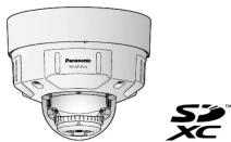
(This illustration represents WV-SFV631L.)
- This manual describes the installation procedures, network camera installation, cable connections, and the angle of view adjustment.
Before reading this manual, he sure to read the Important Information - Before reading this manual, be sure to read the important information.
- This manual describes how to install the network camera using the WV-SFV631L model as an example.
For U.S. and Canada:
Panasonic System Communications
Company of North America, Unit of Panasonic Corporation
Unit of Panasonic Corporation of North America
www.panasonic.com
For customer support, call 1.800.528.6747 Two Riverfront Plaza, New York, NJ 97409-540
Two Riverfront Plaza, Newark, NJ 07 102-5456
Panasonic Canada Inc.
5770 Ambler Drive, Mississ Ontario, L4W 2T3 Canada
Ontario, D4W 215 (905)624-5010
www.panasonic.c
© Panasonic System Networks Co., Ltd. 2014
For Europe and other countries:
Panasonic Corporation
http://panasonic.net
•
Panasonic Systems
Panasonic System Fukuoka, Japan
cc
ce
广力云智慧零售收银系统
Germany
1
rinted in
Major operating controls
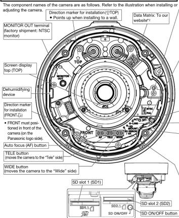
*1 SDXC/SDHC/SD memory card is described as SD memory card
*2 Depending on the scanning application used, the Data Matrix may not be able to be
read correctly. In this case, access the site by directly entering the following URL. http://security.panasonic.com/psr/security/support/gr_sp_select.html
http://security.panasonic.com/pss/security/support/qi_sp_select.html
Standard accessories Making connections
Important Information .... 1 pc. CD-ROM ^+ .... 1 pc. Installation Guide (this document) .... 1 set Code label ^2 .... 1 pc. Warranty card .... 1 set
*1 The CD-ROM contains the operating instructions and different kinds of tool software programs.
*2 This label may be required for network management. The network administrator shall retain the code label.
| The following parts are used during installation procedures. | |
| A Base bracket.... 1 pc. | B Attachment plate.... 1 pc. |
| C Fixing screws for attachment plate(M4 x 8 mm).... 5 pcs.(of them, 1 for spare) | D 4P alarm cable.... 1 pc.E MONITOR OUT conversion plug.... 1 pc.F Template A (for the attachment plate)1 sheet. |
| G Template B (for the base bracket) .. 1 sheet. | H Bit.... 1 pc. |
| I 2P power cable.... 1 pc. | J LAN cable cover.... 1 pc. |
| K Währung tape.... 1 pc. | |


OUT terminal output can be switched for NTSC or PAL monitors.

If the SM unit is this, 14.0% of the 2.3/50 unit is its first unit
If the [Monitor out] is set to [Switch priority] ([Switch priority] is selected by details, refer to the Operating Instructions (included in the CD ROM).


to the comers
below to initialize the network camera
below to initialize the network camera. Over of the camera. When using a PoE bar
Power of the camera. When using a 10E hub, disconnect the LAN cable from the cam ing an external power supply, disconnect the 2P power cable plug from the camera.
power of the camera while holding down the INITIAL SET button, and then keep
the button for 5 seconds or more. About 2 minutes later, The camera will start
ttings including the network settings wi


amera is initialized, the settings including the network settings will be initial-
hat the CRT key (SSL encryption key) used for the HTTPS protocol will not

alizing the settings, it is recommended to write down the settings in advance.
off the power of the camera during the process of initialization. Otherwise, it
initialize and may cause malfunction.
being sent via the network camera Blinks green (accessing)
is able to communicate with the connected device Lights orange

cator cormon: cord^*1 is inserted and could
memory card is inserted and could
I be saved after the SD memory card is
ie SD ON/OFF button is pressed
I be saved to the SD memory card
memory card is removed after holding down Lights green → Blinks green → Lights off 5 button for about 2 seconds
button for about 2 seconds
not be saved to the SD memory card because Lights on
was detected of the SD memory card is
o be used
indicator
o Focus) operation is being executed
s being started
memory card is recognized normally
mality is detected in both SD1 and SD2
camera has started
quality is only dot
formality is only detected in the SDT card use has started.
ra has started
ermality is only detected in the SD2 card
ra has started
Blinks red (Interval of 1 time/ second)
Lights red
Lights red → Lights off
Lights red
Light 122
Lights red
(Interval of 1 time/3 seconds)
Lights red . . Blinks red
Lights fed → Blinks fed (Interval of 2 times/3 seconds)
(interval of 2 times/5 seconds)
Turn off each system's power supply before making a connection. Before making connections,

Connect a LAN cable (category 5 or better, straight)
IMPORTANT
- Use all 4 pairs (8 pins) of the LAN cable (category 5 or better, straight).
• The maximum cable length is 100 m (328 feet).
• Make sure that the PoE device in use is compliant with IEEE802.3af standard. - When connecting both the 12 V DC power supply and the PoE device for power sup-
- When connecting both the 12 V DC power supply and the 1 GE device for power supply, 12 V DC will be used for power supply*.
ply, 12 V DC will be used for power supply. * If a 12 V DC power supply and a RoE hub or router are used at the
If a 12 V DC power supply and a PoE hub of router are used at the same time, network connections may not be possible. In this case, disable the PoE settings.
work connections may not be possible. In this case, disable the Pot
Refer to the operating instructions of the PoE hub or router in use.
* In the situation where a 12 V DC power supply and a PoE hub or router are used at the
same time and the 12 V DC power supply is then disconnected, the power supply may
be stopped and the camera may restart depending on the PoE hub or router used. - When the LAN cable is disconnected once, reconnect the cable after around 2 seconds.
When the cable is quickly reconnected, the power may not be supplied from the PoE device. - When cables are used outdoors, there is a chance that they may be affected by lightning.
In this case, install a lightning arrester just before where the cables connect to the camera.
in this case, Imstand a lightning officer just before where the cable does meet to the corners.
(No text)


microphone/line input cable

- Input impedance: Approx. 2 kΩ (unbals
- Recommended cable length: Less than 1 m /3.28 feet) (for microphone input)
- Recommended cable length: Less than 1 inch (0.25 feet) (for microphone) Less than 40 m (32.8 feet) (for line input)
Less than 10 m (32.8 feet)
- Recommended microphone;
• Supply voltage: 2.5 V ±0.5 V
- Recommended sensitivity of microphone: -48 dB ± 3 dB (0 dB=1 V/Pa,1 kHz)
- Input level for the line input: Approx. -10 dBV

waterproof treatment for the cable joint sections
Adequate waterproof treatment is required for the cables when installing the camera with cables exposed or installing it under the eaves. The camera body is waterproof, but the cable ends are not waterproof.
Be sure to use the supplied waterproof tape at the points where the cables are connected to apply waterproof treatment in the following procedure. Failure to observe this or use of a tape other than the provided waterproof tape (such as a vinyl tape) may cause water leakage resulting in malfunction.


How to wind the supplied waterproof tape
- Also waterproof the 2P power cable (accessory), 4P
alarm cable (accessory), and external connections in
the same way.
- Stretch the tape by approx. twice (see the illustration)
- Stretch the tape by approx. twice (see the illustration) and wind it around the cable. Insufficient tape stretch
and wind it around the cable. Insufficient tape stretch
causes insufficient waterproofing.
• To prevent the LAN cable hook from coming loose
easily, fit the Ⓐ LAN cable cover onto the pigtail
cable as illustrated, and then slide it in the direction
basis as manufactured, and indicated by the army
Indicated by the arrow.
The connector of the LAN cable used with this cam-
era must meet the following restrictions.
Height when inserted (From bottom to hook.)
Max. 16 mm (5/8 inches)
Connector width: Max. 14 mm (9/16 inches)
Connector width: Max. 14 mm (or 10 inches) To install this product outdoors, he wants to use
- To install this product outdoors, be sure to waterproof
the cables. Waterproof grade (IEC IP66 or equiva-
lent) is applied to this product only when it is installed
correctly as described in these operating instructions
and appropriate waterproof treatment is applied. The
and appropriate trans-press treatment is applied. The internal parts of base hospitals are not water-scarved.
Internal parts of base brackets are not waterproofed.


Installation
The installation tasks are explained using 4 steps.
| Step1Make sure all items are prepared before beginning installation. |



There are 4 methods to install the camera to a ceiling or wall as described below. Prepare the required parts for each installation method before starting the installation. The following are the requirements for the various installation methods.
| Installation method | Recommended screw | Minimum pull-out strength (per 1 pc.) |
| [1] Mount the camera on the two-gang junction box using the attachment plate. | M4 screws x 4 196 N (44 bf) | |
| [2] Directly mount the camera onto the ceiling or wall using the attachment plate (when wiring can be installed in the ceiling or wall). | M4 screws x 4 196 N (44 bf) | |
| [3] Mount the camera onto the ceiling or wall using the base bracket (when conduits are used for wiring, or when there is no space available for wiring in the ceiling or the wall).*1 | M4 screws x 4 196 N (44 bf) | |
| [4] Mount the camera embedded to a ceiling using the WV-04169A (ceiling mount bracket: approx. 705 g (1.55 lb)).*2 | — | There is suffi cient strength in the ceiling |
*1 Use 4 screws (M4 × 8 mm, accessory) to fix the attachment plate to the base bracket or WV-Q169A. *2 For information on how to mount the camera embedded to a ceiling using WV-Q169A, refer to the Instruction Manual provided with the WV-Q169A (ceiling mount bracket).
IMPORTANT:
| Procure 4 screws (M4) to secure the attachment plate (accessory) or base bracket ● (accessory) to a ceiling or a wall. |
| The minimum required pull-out capacity of a single screw or anchor bolt is 196 N ● (44 lbf) or more when mounting with the installation method [1] to [3] above. |
| When mounting the camera on a concrete ceiling, use an AY plug bolt (M4) for ● securing. (Recommended tightening torque: 1.6 N m (1.18 lbf ft)) |
| ● Select screws according to the material of the ceiling or wall that the camera will be mounted to. In this case, wood screws and nails should not be used. If a ceiling board such as plaster board is too weak to support the total weight, the ● area shall be sufficiently reinforced. |
Step2 Fixing the bracketsStep1 Preparations
[1] Using a two-gang junction box
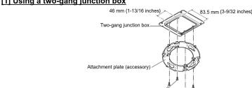
Fixing screws for attachment plate: x4 (M4, locally procured
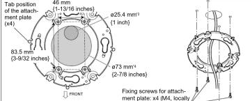
[2] Directly mount the camera to the ceiling or wall using the attachment plate
Attachment plate (accessory)
*3 If the mounting direction of the camera has already been determined Align the FRONT direction (the direction of FRONT 1 marker on the camera that indicates the installation direction when installing the camera) of 5 template A with the desired direction, and drill through a 25.4 mm (1 inch) diameter hole.
*4 If the mounting direction of the camera is not determined yet or if you want to change
the direction of the camera after it has been installed If you want to be able to change the direction of the camera, drill through a 73 mm (2-7/8 inches)
diameter hole in the center. By doing so you can adjust the mounting direction of the camera in 90° increments.
[3] Mount the camera to a ceiling or a wall using base bracket
The base bracket can be fixed in any of the following 6 screwing positions according to ceiling and wall conditions. Match the hole used when installing the camera to any of positions A to E.
Position A Position D
![PANASONIC WV-SFV611L - [3] Mount the camera to a ceiling or a wall using base bracket - 1](/content/2026/05/862462/images/feddbc35eaf7d3c855f9470ba353d79daf889dc54a6ab5f33f1dcf9161f25506.jpg)
Position B
![PANASONIC WV-SFV611L - [3] Mount the camera to a ceiling or a wall using base bracket - 2](/content/2026/05/862462/images/3b2649844a040ca5fdace96cda3ba66a5e2e0fec7cb183b1a63c4e07f5a1d272.jpg)
Position E
![PANASONIC WV-SFV611L - [3] Mount the camera to a ceiling or a wall using base bracket - 3](/content/2026/05/862462/images/9d12fa649f2bc4eadf0de0ff78e0e1e2b2faa16251f02a5e92db633675e8253d.jpg)
Position C
![PANASONIC WV-SFV611L - [3] Mount the camera to a ceiling or a wall using base bracket - 4](/content/2026/05/862462/images/0983d00620a36742a336681c82effd3694c7927ebd5f33b2477b25c13fa161e8.jpg)
Position F
![PANASONIC WV-SFV611L - [3] Mount the camera to a ceiling or a wall using base bracket - 5](/content/2026/05/862462/images/56256dd8bd09f2d0dd9e03dd14a5ca0050869390ad6a582be1bce806277f4e6b.jpg)
*5 The wiring hole diameter is 25.4 mm (1 inch). Select any of the 2 base bracket fixture holes of © template B when installing the base bracket. After mounting the attachment plate, the mounting direction of the camera can be adjusted in 90° increments.
*6 When attaching the base bracket to a one-gang junction box in Position E, secure the base bracket with 2 screws (M4, locally procured).
<When using the conduit on the ceiling
or wall for wiring>
Remove the cap for the female thread for the conduit by using a hexagon wrench (ISO 2936, width across flats S=5 mm (3/16 inches)).
The female thread for conduit is compliant with ANSI NPSM (parallel pipe threads) 3/4 or ISO 228-1 (parallel pipe threads) G3/4.
![PANASONIC WV-SFV611L - [3] Mount the camera to a ceiling or a wall using base bracket - 6](/content/2026/05/862462/images/713a2e76f88a8250cf68f1bb200cffb167ab7f447ed04ae6faf0dc3e665255a3.jpg)
②Mount the attachment plate and
he base bracket.
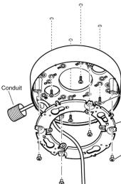
Fixing screws (M4x4, locally
procured) Minimum pull-out strength: 196 N {44.06 lbf} -(per 1 pc.)
Attachment plate (accessory)
Fixing screws for attachment plate: x4 (accessory)
(Recommended tightening torque: 0.78 N·m {0.58 lbf·ft})
![PANASONIC WV-SFV611L - [3] Mount the camera to a ceiling or a wall using base bracket - 8](/content/2026/05/862462/images/85e0528d238c2ac70468c3fc58a7d95650267faa74f7587f4ee6b2d0a03e4575.jpg)
IMPORTANT:
- If open wiring is conducted, be sure to use conduits and run the cables inside
the tubes to protect the cables from direct sunlight.
- Installation work shall be such that there is no exposure to water into the architecture through the conduits having been joined.
Step3 Mount the camera to the attachment plate
①Check the position of attachment mounting screws on the rear side of the camera.
Attachment mounting screws
②Connect cables to the camera according to the instructions in "Making connections", and mount the camera by inserting the attachment
mounting screws into the holes of the attach- mont plates
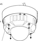
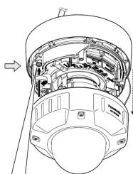
③Loosen the enclosure fixing screws.
④Remove the enclosure from the camera,
and secure the camera using camera fi xing screws.
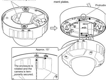
Note:
After cables have been connected to the camera, align the OPEN mark of the enclosure side panel with the protruding part of base bracket, insert 2 attachment mounting screws into the attachment plate, and rotate the camera approximately 15^ . The LOCK mark is moved to the protruding part of base bracket and the camera is temporarily secured. (When directly attaching the attachment plate to a ceiling or wall, align the OPEN mark to the tab position of the attachment plate.)
*The fixing angle of the camera can be rotated in 90° increments.
IMPORTANT
- Disconnect the 12 V DC power source and PoE power source to prevent power from being
- Enclosure is fixed at the installation auxiliary wire to the camera body, please do not
- Enclosure is fixed at the installation auxiliary wire to the camera body, please do not remove the installed auxiliary wire.
• For installations on the wall, to prev - For installations on the wall, to prevent water from dustmidizing on the surfaces of the dehumidifying device, install the camera so that the dehumidifying device does not face up.
If water accumulates on the surface of the dehumidifying device, it cannot function properly.
sure
natural_image
Technical line drawing of a mechanical assembly with internal components and directional arrows (no text or labels)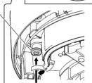
Step4 Adjustment
①Turn on power for the camera by either
connecting a LAN cable or a 12 V DC
power cable, and then remove the protec
tion fi lm from the camera lens
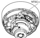
2 Connect the MONITOR OUT conversion plug (accessory) to the MONITOR OUT terminal of the camera, and then connect the monitor for adjustment with a RCA pin cable (locally procured).
The camera is set to be connected to the
NTSC monitor for adjustment at factory shipment
shipment
③Adjust the angle of the camera with the tilt table, pan table, and azimuth adjustment ring, and then adjust the viewing angle by pressing the WIDE or TELE buttons, and tighten the cross slot tilting lock screw finally.
connect Horizontal position (Panning): ±180° RCA pin Vertical position (Tilting): 0° to 85° Image tilt adjustment:
to the -45°(Left) to +300°(Right)
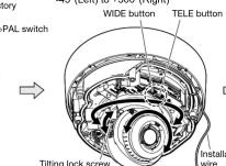
- When adjusting the viewing angle, make sure not to touch the light-blocking rubber ring or IR LED cover. Fingerprints or dirt can reduce the quality of viewed images.
IMPORTANT:
- After adjusting the angle of view, tighten the cross slot tilting lock screw. (Recommended tightening torque: 0.59 N·m (0.44 lbf·ft))
④Insert an SD memory card into the slot, if necessary.
if necessary.
◀insert the SD memory card with its label facing down.
Refer to the Operating Instructions on the provided CD-ROM for further information about the SD memory card settings.
(1) AD = BD = 1
[Non-Text]
[Non-Text]
[Non-Text]
SD1, SD2
SD1, SD2
SD1, SD2
SD1, SD2
SD1, SD2
SD1, SD2
To remove the SD memory card, hold down the SD ON/OFF
button for about 2 seconds. When the flashing SD MOUNT
indicator goes out, you can remove the SD memory card.
After the SD memory card has been replaced, press the
SD ON/OFF button, and make sure the SD MOUNT
indicator is continually lit. (If you replace both SD memory cards, press the SD ON/OFF button after replacing the
cards, press the SD ON/OFF button after replacing the cards.)
If you do not press the SD ON/OFF button after replacing
the SD memory card, the SD MOUNT indicator is
continually lit approximately 5 minutes later.
IMPORTANT:
- Securely tighten all the fixing screws (x4) of enclosure. Otherwise, camera dropping may
result in injury. (Recommended tightening torque: 0.78 N·m {0.58 lbf·ft}) - Defocus may be caused by the reinstalled enclosure. In this case, perform the auto focus
function from the setup menu. - Remove the cover film from the dome cover.
After installing the camera, refer to "Configure the settings of the camera (leaflet)" and perform the camera settings.
[Non-Text]
⑤ Disconnect the monitor for adjustment after adjusting the focus by accessing the
after adjusting the focus by pressing the AE button.
AF button.
Attach the enclosure
(Align the √ mark on the camera body
with the LOCK line on the enclosure
and then mount the enclosure to t
camera body at a straight angle.)
Direction marker
for installation
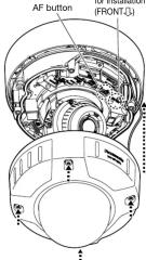
.
[Non-Text]
This image contains no text. The visible element is a stylistic horizontal line, which must be ignored according to the rules.
m = 311
Otherwise, camera dropping may
N·m {0.58 lbf·ft}
n this case, perform the auto focus
“
m = 311
The Ground Truth image displays a single, solid horizontal line, which is a stylistic or background element (like a rule line on paper). According to Rule 2, such lines must be ignored by the OCR result. The provided OCR content is "____", which consists of underscores. Underscores are not equivalent to a solid line and are not permitted under the “Stylistic/Background Lines (Ignore)” rule. Outputting underscores for a stylistic line is incorrect because it misinterprets the line as a placeholder fill-in-the-blank area. Since the OCR output incorrectly rendered a stylistic line as underscores (which should be ignored), this violates the rule. Therefore, the OCR result is inconsistent with the Ground Truth.
ettings of the camera (leaflet)" and
and
[Non-Text]
[Non-Text]

Mærke : PANASONIC
Model : WV-SFV611L
Kategori : Overvågningskamera