
KP 6 - Fjernbetjening Extron - Gratis brugsanvisning og manual
Find enhedens vejledning gratis KP 6 Extron i PDF-format.

Brugerspørgsmål om KP 6 Extron
0 spørgsmål om dette apparat. Besvar dem du kender, eller stil dit eget.
Stil et nyt spørgsmål om dette apparat
Download vejledningen til din Fjernbetjening i PDF-format gratis! Find din vejledning KP 6 - Extron og tag din elektroniske enhed tilbage i hånden. På denne side er alle dokumenter nødvendige for brugen af din enhed offentliggjort. KP 6 af mærket Extron.
BRUGSANVISNING KP 6 Extron
User's Guide
natural_image
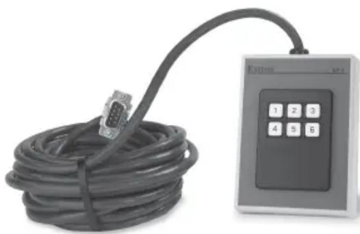
Exterior view of a USB cable with an external control panel (no visible text or symbols)KP 6 Keypad Remote
Keypad Remote Controls
68-694-01 Rev. A
Printed in the USA
Installation and Operation
Introduction
The KP 6 is designed to control MSW 4 Series, SW AV Series (4 and 6 input models only), SW VGA/ Ars Series, and SW RGBHV/ A Series switchers, or other Extron products with contact closure ports or ports labeled as “Remote.”
The KP 6 is a contact closure remote for selecting the switcher's input. When a number key is pressed, the wire associated with that input is momentarily shorted to ground, making the switcher switch to that input.
The KP 6 can control up to 6 inputs and requires no power.
Installation
Installation with a 9-pin D-sub connector
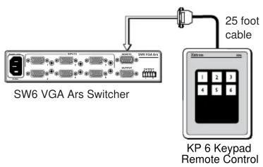
Many switchers, such as the SW6 VGA Ars Switcher, come equipped with a 9-pin D-sub connector. To use the KP 6 Keypad Remote Control on this type of switcher, install it as follows:
- Power down the switcher.
- Connect the KP 6 adapter's 9-pin plug to the contact closure connector on the switcher's rear panel.
- Position the KP 6 Keypad for the most convenient operation.
- Power up the switcher.
flowchart
graph TD
    A["SW6 VGA Ars Switcher"] -->|25 foot cable| B["KP 6 Keypad Remote Control"]
    A --> C["Switcher"]
    B --> D["Switcher"]
Figure 1 — Typical KP 6 application (with 9-pin D-sub connector)
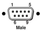
| Pin | Contact closure | Function | Wire color |
| 1 | In#1 | Input #1 | Brown |
| 2 | — | Not used | — |
| 3 | — | Not used | — |
| 4 | In#2 | Input #2 | Red |
| 5 | Gnd | Signal ground | Black |
| 6 | In#3 | Input #3 | Orange |
| 7 | In#4 | Input #4 | Yellow |
| 8 | In#5 | Input #5 | Green |
| 9 | In#6 | Input #6 | Blue |
Figure 2 — 9-pin Sub-D connector pinout
Installation with a captive screw connector
Some switchers, such as the MSW 4 Series, are not equipped with 9-pin D-sub connectors and have a 3.5mm, 5-pole captive screw connector (labeled "Contact") instead. In order to use the KP 6 Keypad Remote Control with these switchers, a captive screw connector (included with the switcher) must be used. To use a captive screw connector, the existing 9-pin D-sub connector must be removed from the cable and a captive screw connector installed.
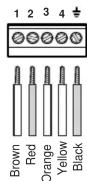
To install the captive screw connector, remove the wire from the 9-pin D-sub connector, then strip the wires and insert them into the new connector (supplied with the switcher). Wire the connector as shown here. Tighten the screws to secure the wires. Clip off the green and blue wires.

Do not tin the stripped wire leads before installing the captive screw connector. Tinned wires are not as secure in the captive screw connectors and could pull out.
Install the KP 6 Keypad Remote Control on this type of switcher as follows:
- Rewire the connector on the KP 6 Keypad Remote Control.
- Power down the switcher.
- Connect the KP 6 adapter's captive screw connector to the "Contact" connector on the switcher's rear panel.
- Position the KP 6 Keypad for the most convenient operation.
- Power up the switcher.
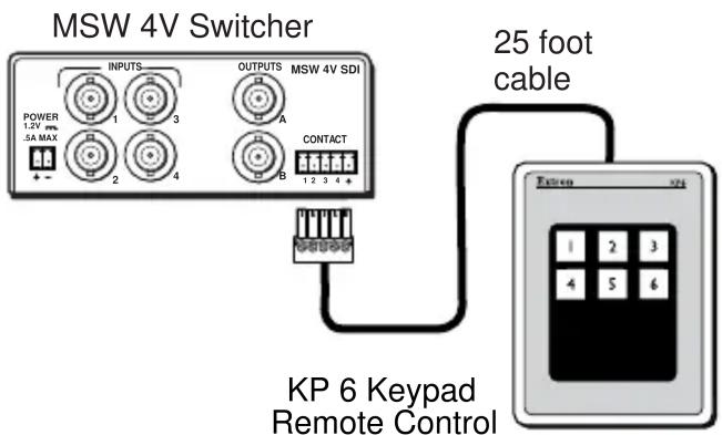
Figure 3 — KP 6 application (with 5-pole captive screw connector)
Operation
To select an input using the KP 6 Keypad Remote Control, press the number key for the desired input.
Specifications
Power ...... None required
Temperature/humidity ...... Storage -40° to +158° (-40° to +70°C)/ 10% to 90%, non-condensing
Operating ....+32° to +122° (0° to +50°C)/ 10% to 90%, non-condensing
Enclosure type ...... Plastic
Approvals ...... CE
MTBF 30,000 hours
Warranty .... 3 years parts and labor