HE-204 - Ukategoriseret Home Easy - Gratis brugsanvisning og manual
Find enhedens vejledning gratis HE-204 Home Easy i PDF-format.

Brugerspørgsmål om HE-204 Home Easy
0 spørgsmål om dette apparat. Besvar dem du kender, eller stil dit eget.
Stil et nyt spørgsmål om dette apparat
Download vejledningen til din Ukategoriseret i PDF-format gratis! Find din vejledning HE-204 - Home Easy og tag din elektroniske enhed tilbage i hånden. På denne side er alle dokumenter nødvendige for brugen af din enhed offentliggjort. HE-204 af mærket Home Easy.
BRUGSANVISNING HE-204 Home Easy

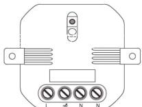
HE-204 300W Dimmer Ceiling Module
The Byron HomeEasy range allows you to individually tailor your lighting ambience and mood scenes in your home or business at the touch of a button. The system operates by sending wire free
signals from the remote control to the receiver units.
30 Metre Range
Remote On/Off setting
Max Load: 300W Incandescent
Lighting Only
INSTALLATION WARNINGS: BEFORE COMMENCING INSTALLATION ISOLATE YOUR MAINS ELECTRIC SUPPLY
Read the instructions care fully before starting the installation process and keep them for future reference. If you are in any doubt on the installation process, consult a qualified electrician.
This product should be installed in accordance with the relevant sections of the building
regulations code, and the current edition of the IEE Wiring Regulations (BS 7671:Requirements for electrical installations) and appropriate statutory regulations.
Do not install ceiling receivers on lighting circuits used to supply other products such as extractor fans and shaver socket outlets. Do not exceed the Maximum Power Rating of 300W, Incandescent lighting only
As of 1 April 2004, new installations in the UK should be wired using the EU harmonised colours for the supply conductors:
New colours:
BROWN = Live BLUE = Neutral Earth = Yellow/Green
Old colours: RED = Live BLACK = Neutral
Electrical installations in bathrooms, kitchens, gardens, floor and heating systems,
swimming pools, saunas and extra-low voltage lighting are classed as special installations and must
V1.0 Product Compatibility:
The following lighting types will NOT work with the HE-204 Ceiling Modules: G23, Metal Halide High Pressure sodium,
CLF, Linear/Compact Fluorescents,
SLE-PRO, PLE-C Pro,
Single Ended High Pressure Lamps
The HE-204 Ceiling Modules are compatible with the following lighting types:
G9, Strip & Architectural, PAR30,
PAR36, SES (Candle/Round, PAR38,
PAR20, GLS BC, GLS ES,
GU10, SBC (Candle/Round), K1/9/11/12,
G4, G6.35, MR16,
MR11
Product Specification:
Ceiling Receiver Module:
Input: 230V \~ 50Hz
Max Load: 300W
(Incandescent Load)
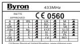
Frequency: 433.92MHz
Fused: 1.6A
Indoor Use Only
Warning: Never Exceed the Product Specification
Pairing/Deleting the Remote Control Socket:
Up to Six remote control units can be paired with each receiver module.
To program a receiver module, press "Learn" button. The LED will start to flash, now press the selected "ON" button on the remote control, the LED will stop flashing.
The units are now paired together, you can test this by pressing the selected "ON/OFF" button.
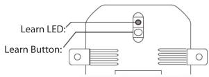
Deleting Remote Control:
To delete a remote control that has been paired with a HE-204 receiver module, simply press "Learn" button. The LED will start to blink; press the "Off" button on the remote control, the LED will blink twice to confirm that the remote control has been removed from the receivers memory.
Ceiling Module Reset:
To delete all the remote control units from the memory of the receiver module, hold the "Learn" button for more than 6 seconds, the LED will start to blink continuously. Press the learn button again, the LED will blink twice to confirm the deletion of all remote controls from the receiver memory.
Dimming Module:
To dim the ceiling module, switch the unit on by pressing the "On" button and the press "On" again. This will start the dimming cycle to select the required level press "On".
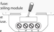
Changing Fuse:
The HE-204 is fuse protected, to change the fuse: 1. Isolate the mains power supply from the ceiling module
-
Using a small screw driver, remove the fuse holder and replace the fuse with a new 1.6A fuse.
-
Replace the fuse holder and reconnect the mains supply
Contact Details: HelpLine - 0845 2301231
C H Byron
34, Sherwood Rd
Aston Fields
Bromsgr B60 3DR
Tel: 0845 2301231
Fax: 01527 557701
Web: www.chbyron.com E-mail
E-mail: support
support@chbyron.com
Installation Notes:
When installing HE-204 Ceiling Modules in a existing lighting circuit, conventional light switches should be disconnected and terminated as part of the installation.
If your lighting circuits using ceiling roses, it is recommended that the current wiring connections should be re-terminated using a suitable junction box.
Any existing switches currently controlling the light fitting should be disconnected and suitably terminated.
The HomeEasy Ceiling Module is designed to be connected to the existing permanently live lighting circuit between a convenient junction box and the light fitting.
Any existing switches currently controlling the light fitting should be disconnected and appropriately terminated.
Lighting circuits supplying Ceiling Receivers should always be protected by a 5 Amp rewire-able fuse or equivalent Miniature Circuit Breaker (MCB) located within the Consumer Unit. Under no circumstances should any protection devices with higher ratings be used.
** Ceiling Modules, are not designed to be used with loop-in/loop-out wiring, a suitable junction box needs to be used if its necessary to connect the supply to further fittings, the unit is designed for permanent installation.
The HE-204 Ceiling Modules are designed to be mounted inside a suitable enclosed housing, which are dry and adequately ventilated (indoor use). For outdoor use a suitable IP56 enclosure must be used. The ceiling receiver module is designed to be maintenance free, but where possible access should be available when needed.
If in any doubt consult a qualified Electrician
WARNING: Before installing the HomeEasy Ceiling Modules, isolate the circuit at the fuse/MCB board.
Connect the supply Live and Neutral conductors to the Receiver terminals marked L and N SUPPLY.
Connect the cable from the light fitting to the Receiver terminals marked L(Load) and N(Neutral).
For earth continuity the supply and load Earth conductors must be terminated externally using a suitably insulated terminal block.
Wiring Diagram: Standard Installation
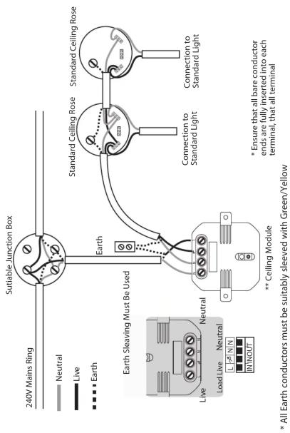
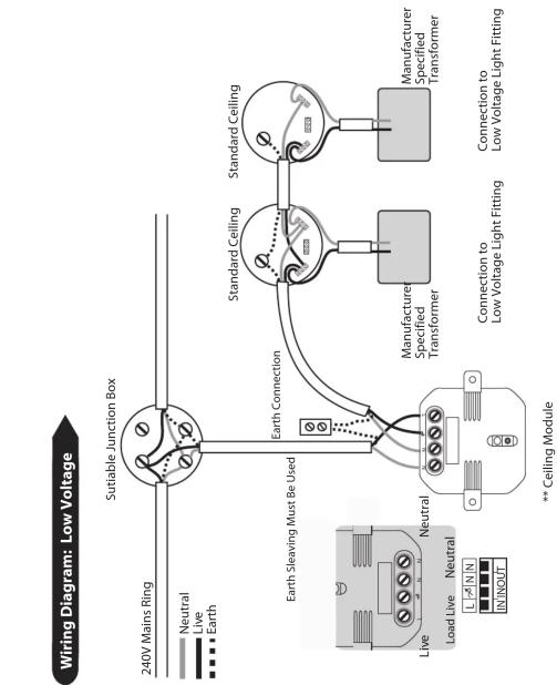
* All Earth conductors must be suitably sleeved with Green/Yellow