A52-DB9F - Ukategoriseret Moxa - Gratis brugsanvisning og manual
Find enhedens vejledning gratis A52-DB9F Moxa i PDF-format.

Brugerspørgsmål om A52-DB9F Moxa
0 spørgsmål om dette apparat. Besvar dem du kender, eller stil dit eget.
Stil et nyt spørgsmål om dette apparat
Download vejledningen til din Ukategoriseret i PDF-format gratis! Find din vejledning A52-DB9F - Moxa og tag din elektroniske enhed tilbage i hånden. På denne side er alle dokumenter nødvendige for brugen af din enhed offentliggjort. A52-DB9F af mærket Moxa.
BRUGSANVISNING A52-DB9F Moxa
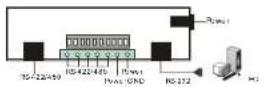
RS-422/RS-485 Pinouts
The RS-422/RS-485 port with RJ45 connector or Terminal Block Connector is depicted as
RJ45 Connector

Terminal Block Connector
follows.
●RS-422
A52/A53
RJ45 Jack
| Connector Pinouts | Signals |
| 1 | TxD-(A) |
| 2 | RTS-(A) |
| 3 | RTS-(B) |
| 4/7 | SG |
| 5 | TxD-(B) |
| 6 | RxD+(B) |
| 8 | CTS-(B) |
| 9 | CTS-(A) |
| 10 | RxD-(A) |
DTE Device
| A52/A53Terminal Block Connector Pinouts | |
| Signals | |
| 1 | TxD |
| 2 | TxD |
| 3 | RxD |
| 4 | RxD |
| 5 | SG |
| 6 | Power |
| 7 | VCCA |
Note: Pins 6 and 7 of the Terminal Block are for Power GND and Power Input, which is an alternate option for power adapter. Be careful TO NOT confuse RS-422/RS-485 GND with Power GND. SG: Signal Ground
©RS-485
A52/A53
| RJ45 Jack Connector Pinouts | Signals |
| 1 | Data-(A) |
| 4 | SG |
| 5 | Data-(B) |
| 7 | SG |
A52/A53
Terminal Block
| Connector Pinouts | Signals |
| 1 | Data-(B) |
| 2 | Data-(A) |
| 5 | SG |
| 6 | Power GND |
| 7 | VCCA 9V |
Note : Pins 6 and 7 of the Terminal Block are for Power GND and Power Input, which is an alternate option for power adapter. Be careful TO NOT confuse RS-422/RS-485 GND with Power GND. SG: Signal Ground
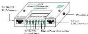
Serial Communication Interface Conversion Solution
Transio A52/53
Smart RS-232 to RS-422/485
Bi-directional Converter
Overview
Transio A52/53 is a smart RS-232 to RS-422/485 bi-directional converter, which allows one RS-232 port to be converted into an RS-422 or RS-485 port. With A52/53 you can control up to 32 devices, within 1.2 km, in a multidrop environment.
Transio A52/53 is a Moxa Green Product. Moxa's Green Products satisfy the RoHS directive of the European Parliament, and accordingly, do not contain cadmium and cadmium compounds, hexavalent chromium compounds, lead and lead compounds, mercury and mercury compounds, PBBs (polybrominated biphenyls), or PBDEs (polybrominated diphenyl ethers).
To ease 2-wire RS-485 half-duplex control, fully Automatic Data Direction Control (ADDC) intelligence that requires no baud rate switch settings is designed into each A52/53, simplifying RS-485 software programming. Your applications can easily manage data transmitting and receiving via the half-duplex RS-485 port without using additional code. Compared to other products that require setting the clock speed manually with switches, A52/53 lets you avoid many developing and maintenance hassles.
To meet the high reliability required by harsh industrial environments, all RS-422/485 signals provide TVS protection, and ESD up to 25 KV. In addition, A53 provides 2 KV of optical isolation protection for all signals at the RS-422/485 end.
Features and Specifications
- Serial interface: RS-232, RS-422/485
• Port types: RS-232; RJ45;
RS-422/485: RJ45 or Terminal Block
- High speed, baud rate up to 921.6 Kbps; no switch setting needed
- Signals:
RS-232: TxD, RxD, RTS. CTS, DTR, DSR, DCD, GND;
RS-422: TxD+(B)/-(A), RxD+(B)/-(A),
RTS-(B)-(A), CTS+(B)-(A), GND; RS-485-Data+(B)-(A), GND
• Supports fully Automatic Data Direction Control (ADDC) with no baud rate switch settings for RS-485
• RS-485 data control modes: auto (ADDC) or by RTS
• RS-422 supports CTS, RTS signals for hardware flow control
• LED indicators for power and 4 signal states (TxD, RxD, RTS, CTS)
- All RS-422/485 signals provide TVS protection. (ESD 8 KV, EFT 2KV)
- All RS-422/485 signals support up to 2 KV (DC) of optical isolation protection (A53 only)
- Provides overloading protection when there are 2 signals shorted together at the RS-422/485 end
- Built-in 120 ohm termination resistors for RS-422/RS-485 (selectable with jumper by RS-485 mode)
• Supports up to 32 units connected in an RS-485 multidrop network
- CF approval
- 9V I.SA UL/TUV 110V/230V power adapter can support up to 4 converters
- An external power adapter is required, with input voltage for the converter ranging from
Fising Screw
DC +9V to +30V.
- Operating temperature: 0 to 55^ C - Dimensions: 90 × 60 × 21 ~mm
- Mounting Kit: Plastic Plates and screws for mounting A52/53 on the wall or any surface
• Power consumption: A52: 157 mA max. (+9V); A53: 285A max. (+9V)
Applications
- Multipoint data acquisition
- Factory automation
- Remote serial device control
- Building security automation
• Critical industrial control
MOXA®
www.moxa.com
Moxa Inc.
Transio A52/53 User's Manual
P/N: 1802000520516
Seventh Edition
Installation
Switch and jumper settings
To change the operation mode, remove the two screws on top of the converter, open the cover, and then use the array of sliding switches to set the desired mode.
DIP switches are used to select the operation mode (RS-422 or RS-485). For RS-485 mode, the control mode (By RTS or ADDC) is also set by DIP switch.
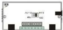
Internal view of A52/53
| SW1 | ||
| RS-422 mode | Off | |
| RS-485 mode | On* | |
| SW2 | |
| By RTS Off | |
| Auto Data Direction Control (ADDC) On* | |
(* Default settings)
In RS-422 mode, RxD is automatically set with a 120 ohm terminating resistor.
In RS-485 mode, the 120 ohm terminating resistor is set by one jumper.
When shorted, the resistor is enabled.
Basic Communication Wiring
Before placing a converter in an existing network, the converter should be properly configured. The following diagrams show typical layouts for both converters.
| RD(1) | R(D)(2) | RD-(B) | RD-(A) |
| RD(3) | RD(3) | RD-(A) | RD-(A) |
| RD(5) | RD(4) | RD-(B) | RD-(B) |
| RD(9) | RD(5) | RD-(A) | RD-(A) |
| RD(10) | RD(8) | GND | GND |
| RD(17) | GND(7) | ||
| RD(18) | RD(8) | ||
| DTR(20) | DTR(20) |
| T(D)(2) | RD(2) | Data + (B) | Data + (C) |
| RD(3) | RD(3) | Data - (A) | Data - (A) |
| RTS(4) | CTS(4) | GND | GND |
| CTS(5) | RTS(5) | ||
| DTR(6) | DTR(6) | ||
| CND(7) | CND(7) | ||
| CDD(8) | CDD(8) | ||
| DTR(20) | DSR(20) |
LED Indicators
LED indicators for TxD, RxD, RTS, CTS signals and PWR are located on top of A52/A53. The indicator light is NOT lit when there is no signal, or the power is off.
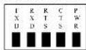
TxD: Shows green when connected and transmitting data from RS-232 to RS-422/485.
RxD: Shows green when connected and receiving data from RS-232 to RS-422/485.
RTS: Shows green when connected and RS-232 RTS Signal is ON.
CTS: Shows green when connected and RS-232 CTS Signal is ON.
PWR: Shows green when power is ON
Power supply
A52/53 converters are designed for standard 24 VDC unregulated power for use in industrial environments. Operation is guaranteed when using any power supply between +9 and +30 VDC, 350 mA.
An optional power adapter (9V 1.5A UL/TUV 110V/230V) can support up to 4 converters (see the following diagram).
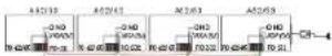
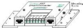
A52/53 Converter Connection Diagram
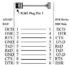
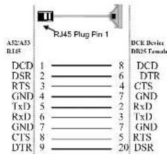
RS-232 Pinouts
The RJ45 port for the RS-232 signal is shown in the following figure.
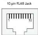
A52/A53 RJ45
Connector Pinouts RS-232 Signals
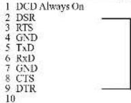
Note: Each group of (DTR, DSR) pins are shorted, freeing users from the hardware flow control cable wiring problem. For this reason, we list two types of RS-232 cable wiring below.
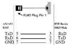
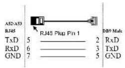
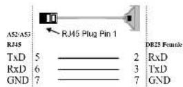
Type 1: To connect the RS-232 side of A52/A53 to a DTE (e.g., PC COM1/2) or DCE (Be sure to check the precise DTE/DCE pinouts. The following DTE/DCE pinouts are just an example)
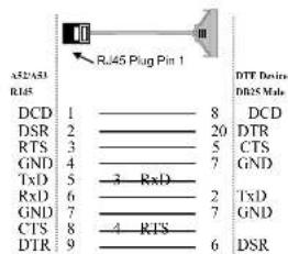
Type 2: You can connect the RS-232 side of A52/A53 to a DTE, e.g., a terminal or PC COM1/2, with 3-pin wiring if you don't need hardware flow control.