CF2300M - Symaskine Yamato - Gratis brugsanvisning og manual
Find enhedens vejledning gratis CF2300M Yamato i PDF-format.

Brugerspørgsmål om CF2300M Yamato
0 spørgsmål om dette apparat. Besvar dem du kender, eller stil dit eget.
Stil et nyt spørgsmål om dette apparat
Download vejledningen til din Symaskine i PDF-format gratis! Find din vejledning CF2300M - Yamato og tag din elektroniske enhed tilbage i hånden. På denne side er alle dokumenter nødvendige for brugen af din enhed offentliggjort. CF2300M af mærket Yamato.
BRUGSANVISNING CF2300M Yamato
1jamato®
Instruction Manual
HIGH SPEED FLAT BED CHAINSTITCH MACHINE
CF2300M
natural_image
Industrial sewing machine with visible mechanical components and no text or symbols1. Installation 1
1-1 Supporting board installation (for semi-submerged type) 1
1-2 Belt cover attachment 1
2. Sewing speed and Motor 2
2-1 Sewing speed and pulley's rotating direction 2
2-2 Motor and belt 2
3. Lubricating oil 3
3-1 Fitting oil 3
3-2 Lubrication 3
3-3 Oil sight gauge and oil sight top nozzle 3
3-4 Changing oil 3
3-5 Checking and changing oil filter 4
4. Proper operation 5
4-1 Fitting needle 5
4-2 Needle installation 5
4-3 Threading 5
4-4 Thread tension 6
4-5 Presser foot pressure 6
4-6 Presser foot adjustment 6
4-7 Stitch length adjustment 7
4-8 Differential feed adjustment 8
4-9 HR and SP devices 9
5. Adjustments 10
6. Specifications 11
1. Installation
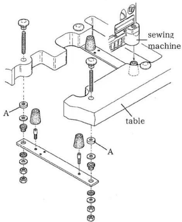
1-1 Supporting board installation (for semi-submerged type)
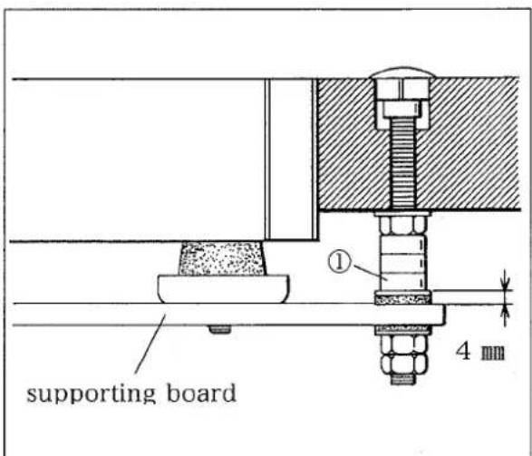
☆Required numbers of spacers① CF2300M class
| Thickness of Table | Number of 1 |
| 40 mm | 3pcs. ×4=12 |
| 45 mm | 2pcs. ×4=8 |
| 50 mm | 1pc. ×4=4 |
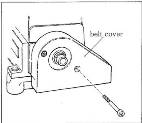
1-2 Belt cover attachment
Attach the belt cover to the machine referring to the figure.
2. Sewing speed and Motor
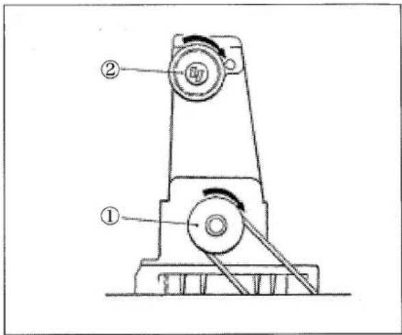
2-1 Sewing speed and pulley's rotating direction
The maximum and ordinary sewing speeds are shown in the table below.
The rotating direction of the pulley ① is clockwise as shown in the figure.
The rotating direction of the handwheel ② is also clockwise.
| Model | Max. Sewing Speed | Ordinary Sewing Speed |
| CF2300M (with spreader) | 5,500 r.p.m. | 5,000 r.p.m. |
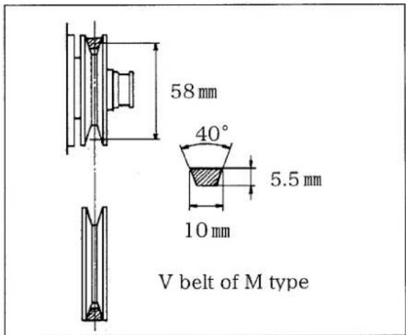
2-2 Motor and belt
Use a 3-phase, 2-pole 550W (3/4HP) clutch motor and a V belt of M type. Position the motor so that its center aligns with that of the machine pulley when the pedal is toed down and the pulley moves to the left.
| Diameter of Motor Pulley (mm) | Sewing Speed (rpm) | |
| 50Hz | 60Hz | |
| 80 | 4,500 | |
| 90 | 5,000 | |
| 95 | 4,500 | 5,300 |
| 100 | 4,800 | 5,500 |
| 105 | 5,000 | |
| 115 | 5,500 | |
* Diameters of pulleys on the market are at intervals of 5mm; the above measurements are the nearest values to the calculated ones.
3. Lubricating oil
3-1 Fitting oil
Use YAMATO SF OIL.
3-2 Lubrication
At shipment, oil is drained out of the machine.
Before operation, remove the rubber seal plug ① indicated with "OIL-IN" and supply oil to the machine until the oil surface comes to the upper line on the oil sight gauge ③.
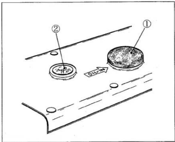
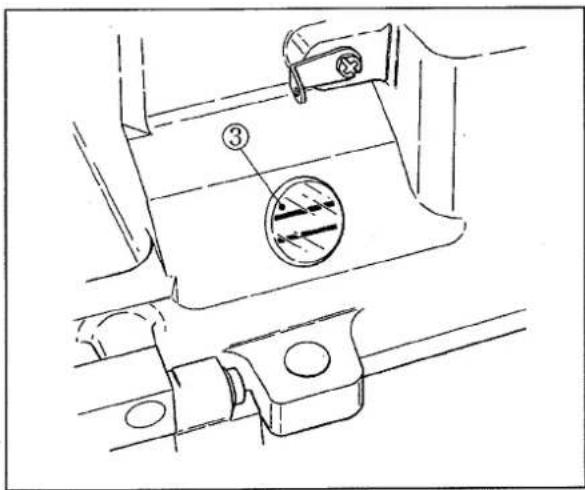
3-3 Oil sight gauge and oil sight top nozzle
Check the oil sight gauge ③ everyday before operation. when the oil surface is below the lower line, supply oil.
Be sure that oil comes out of the nozzle ② whenever starting the machine.
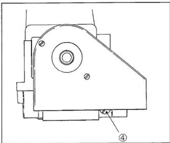
3-4 Changing oil
To ensure that a machine offers a long service life, change oil completely after operating a new machine for around 250 hours.
To change oil, take the following steps.
(1) Remove the V belt from the motor pulley and the machine from the table.
(2) Remove the screw④ and drain oil.
At this moment, be careful so that oil does not attach to the V belt.
(3) After draining oil, tighten the screw④ securely.
(4) To supply new oil, see "5-2 Lubrication".
natural_image
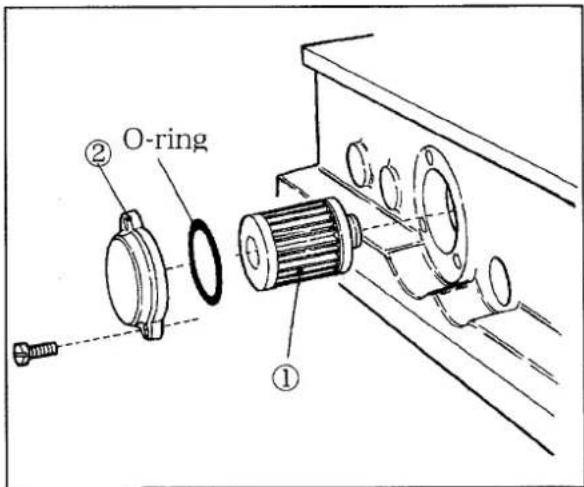
Technical line drawing of a mechanical component with mounting holes and a numbered label (no text or symbols present)3-5 Checking and changing oil filter
Check the oil filter ① every 6 months or whenever the nozzle splashes no or too little oil even if the oil amount in the oil reservoir is enough.
To check the filter①, remove the oil filter cap②.
When the filter ① is clogged, change it with new one.
Note: When removing the cap ②, be careful not to drop the oil remaining in the filter①.
4. Proper operation
4-1 Fitting needle
Use UY128GAS needles.
| Japanese sizes | 9 | 10 | 11 | 12 | 13 | 14 |
| Metric sizes | 65 | 70 | 75 | 80 | 85 | 90 |
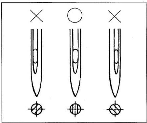
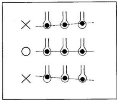
4-2 Needle installation
When changing a needle, install a needle so that its groove faces straight backward as shown in the figure.
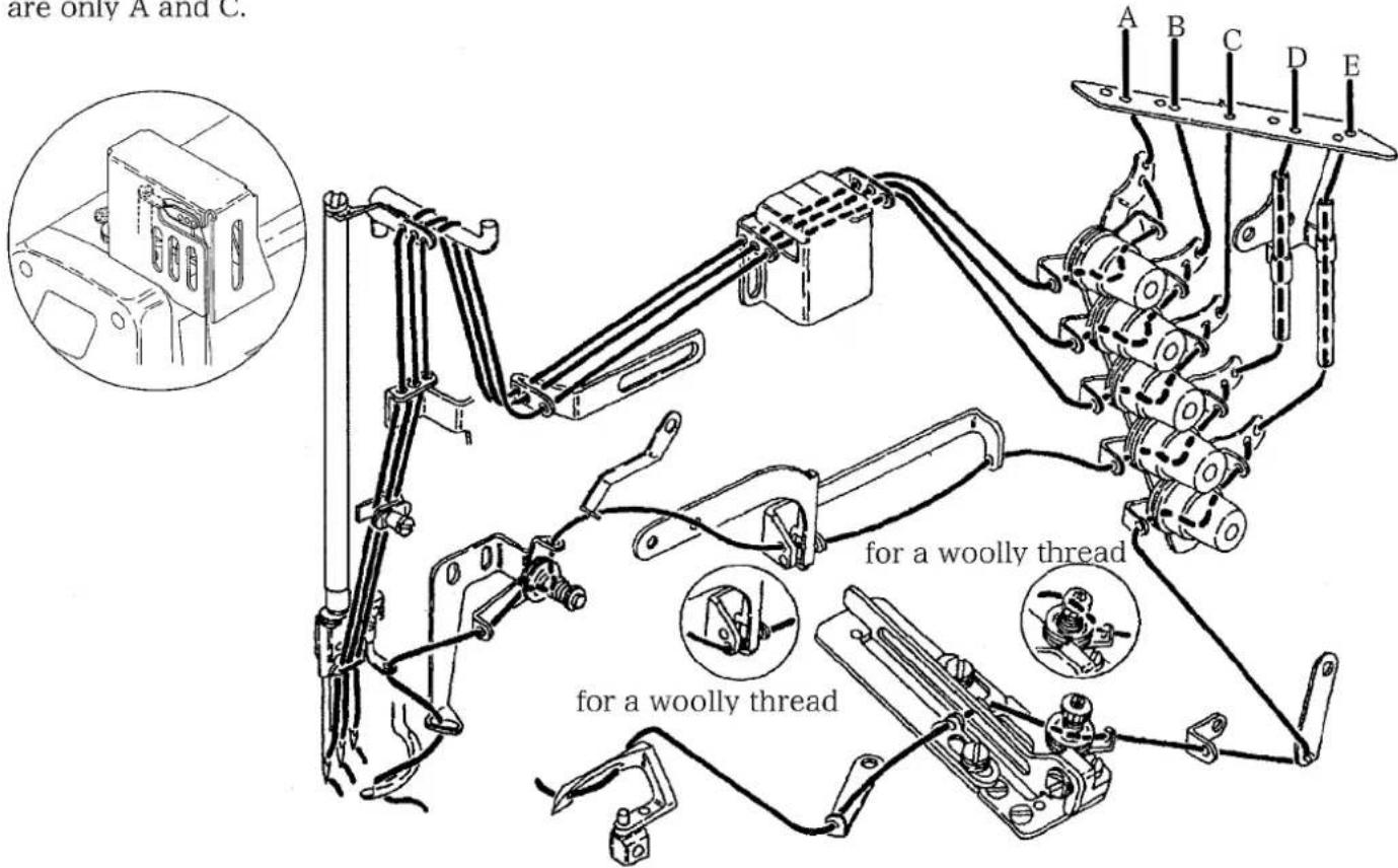
4-3 Threading
Thread the machine correctly referring to the figure.
Incorrect threading can cause troubles such as skip stitches, thread breakage, and uneven seams.
A, B, C: needle threads, D: top cover thread, E: looper thread
The figure shows the threading for a 3-needle machine. In a 2-needle machine, needle threads are only A and C.
4-4 Thread tension
Thread tension changes according to kinds of threads, needle distances, stitch lengths, and so on. According to sewing conditions, adjust each thread tension as low as possible to form stable stitches.
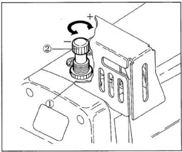
4-5 Presser foot pressure
Adjust the presser foot pressure as low as possible to form stable stitches.
To change the pressure, loosen the lock nut ① and turn the adjusting screw ②.
To increase the pressure, turn the screw ② clockwise.
To decrease the pressure, turn the screw ② counterclockwise.
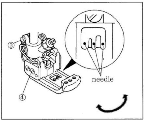
4-6 Presser foot adjustment
Loosen the screw ③ and move the presser foot ④'s yielding section to the left or right so that the needles pass the needle hole centers. This is the proper left-and-right position of the yielding section.
Then, tighten the screw③ securely.
4-7 Stitch length adjustment

WARNING
When changing the stitch length, ALWAYS turn the power switch OFF.
The stitch length can be adjusted from 1.4mm to 3.6 mm.
The table below shows numbers of stitches per inch and per 30 mm when the stitch length is 3.6, 2.4, and 1.4 mm.
| Stitch Length (mm) | Stitches per | |
| Inch | 30 mm | |
| 3.6 | 7 | 8 |
| 2.4 | 10.5 | 12.5 |
| 1.4 | 18 | 21 |
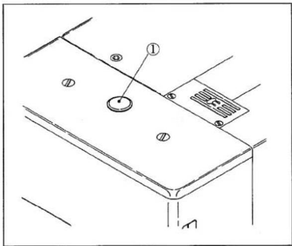
☆How to change stitch length
Keep pressing the pushbutton① lightly and rotate the machine pulley. At a certain point, the button ① enters into the machine. Here, press strongly the button ① and rotate the machine pulley.
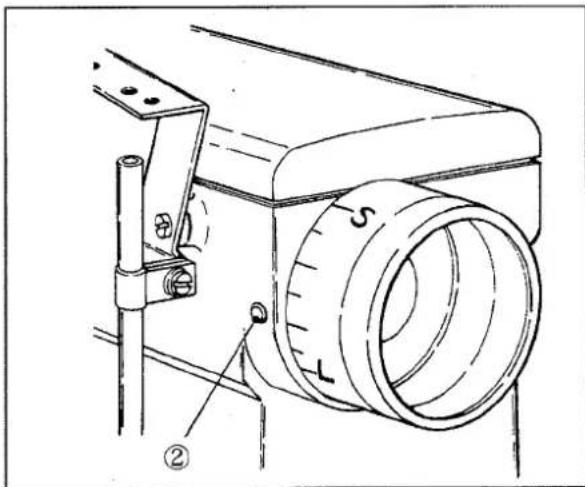
To lengthen the stitch length, rotate the pulley clockwise.
When "L" mark is set to the mark②, the stitch length is 3.6mm.
To shorten the stitch length, rotate the pulley counterclockwise.
When "S" mark is set to the mark②, the stitch length is 1.4mm.
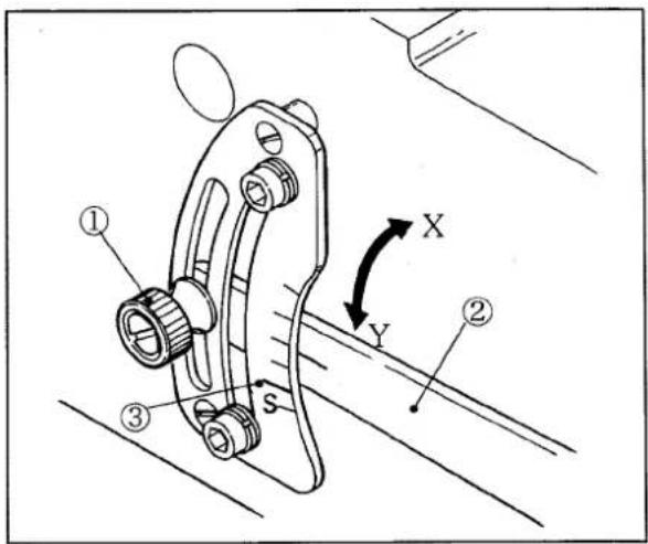
4-8 Differential feed adjustment
(1) Normal differential feed (gather sewing)
Loosen the nut ① and move the lever ② up or down.
Then, set it at a desired position by tightening the nut① securely.
When the lever ② is set to the scale(long)③, the ratio of the main feed to the differential feed is 1:1.
To obtain normal differential feed, raise the lever ② to the arrow direction X from this position.
The scales indicate 1:1.25, 1:1.5, 1:1.75, 1:2 from the scale③ up.
(2) Reverse differential feed (stretch sewing)
To obtain reverse differential feed, lower the lever ② to the arrow direction Y from the scale ③.
When it is set to "S", the ratio of the main feed to the differential feed is 1:0.7.
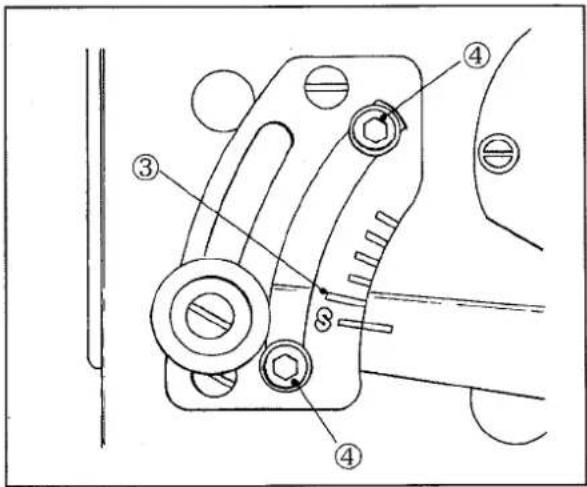
(3) Differential feed adjustment during operation
To adjust the differential feed during operation, connect a chain to the lever②.
Use the two stoppers④ to limit the lever②'s movable range during operation.
☆The range of differential ratio changes according to the stitch length.
Please refer to the table below.
| Stitch Length | Max. Normal Differential Ratio | Max. Reverse Differential Ratio |
| 3.6 mm | 1:1.2 | 1:0.7 |
| 2.5 mm | 1:1.6 | 1:0.7 |
| 2.0 mm | 1:1.8 | 1:0.7 |
| 1.4 mm | 1:2 | 1:0.7 |
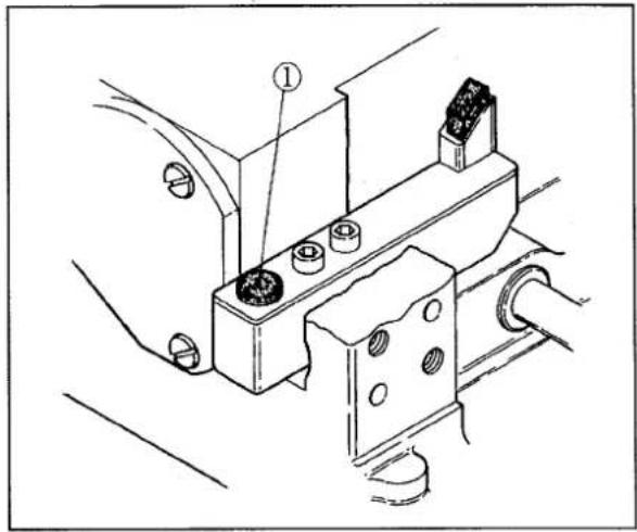
4-9 HR and SP devices
When sewing at high speeds or using synthetic threads or materials, thread breakage and skip stitches often happen. To reduce these problems, use the HR device (a needle point cooling device) and the SP device (a needle thread oiling device). Use silicon oil (dimethyl silicon oil) for these devices.
Note: Check sometimes the oil amount by removing the plug① of the HR container and opening the lid② of the SP container.
When the amount is low, supply oil.
When not using the HR and SP devices, remove the felts from the devices.
CAUTION
When the device is not used, remove the felts ① and ② from the device. If it is left in the device, the sewing condition may be adversely affected.
When silicone oil is adhered to other than the device, be sure to wipe it off. If this precaution is not observed, a failure may result in the machine.
natural_image
Technical line drawing of a mechanical assembly with labeled components (no text or symbols)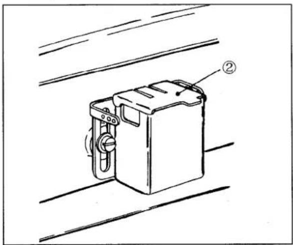
natural_image
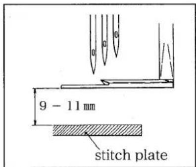
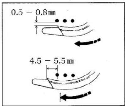
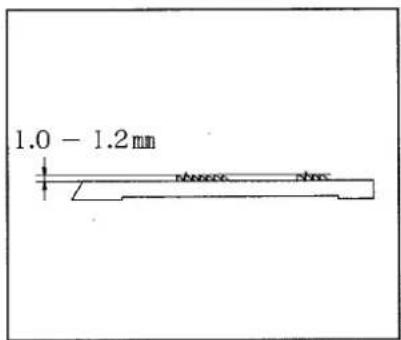
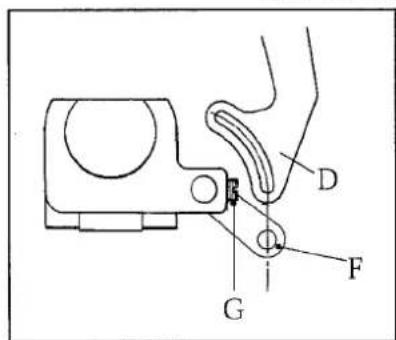
Line drawing of a mechanical device with labeled parts (no text or symbols present)5. Adjustments
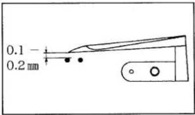
Looper's receding amount
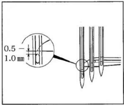
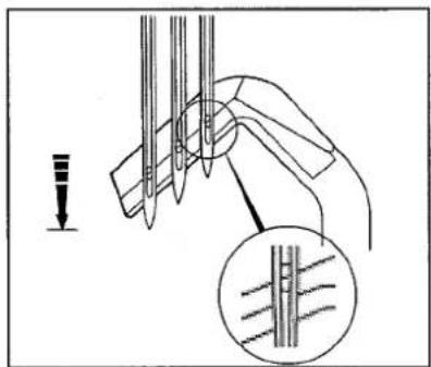
Needle bar height
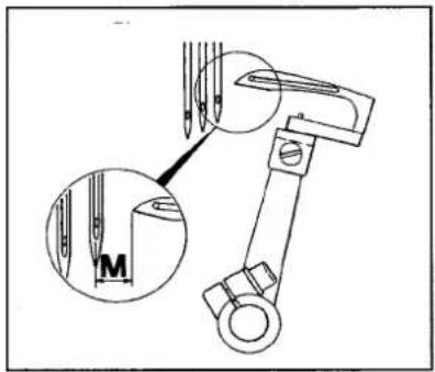
Needles and stitch plate
| Needle Distance (Mark) | M |
| 3.2 mm | 4.4 mm |
| 4.0 mm | 4.0 mm |
| 4.8 mm | 3.6 mm |
| 5.6 mm | 3.2 mm |
| 6.4 mm | 2.8 mm |
Three needles
Two needles
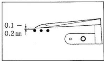
Needle guard (rear)
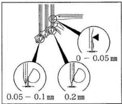
Needle guard (front)
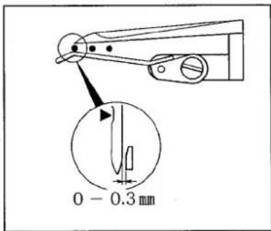
Spreader
Feed dog height
Top cover thread guide
| Dimensions | Length 500mm Width 250mm Height 430mm |
| Weight | 41 kg |
| Stitch Type | ISO 406, 407, 602, 605 |
| Applications | Plain and joint sewing for knitted materials |
| Sewing Speed | Up to 5,500 r.p.m. (with spreader) |
| Stitch Length | 1.4 - 3.6mm 7 - 18 stitches per inch (25.4mm) 8 - 21 stitches per 30 mm |
| Needle System | UY128GAS #65 - #90 |
| Needle Distance | 2 needles: 3.2, 4.0mm 3 needles: 4.8, 5.6, 6.4mm |
| Needle Stroke | 31 mm |
| Presser Foot Lift | 7.0mm (with spreader) |
| Feed Regulation | Pushbutton system |
| Differential Ratio | Maximum normal differential ratio: 1:2 Maximum reverse differential ratio: 1:0.7 |
| Differential Feed Regulation | Adjustment during operation is also possible by moving external lever |
| Lubrication | Automatic lubrication by trochoid-shaped pump |
| Lubricating oil | YAMATO SF OIL |
| Capacity of Oil Reservoir | 1,100 cc |
| Installation | Semi-submerged type |

YAMATO (CHINA) CO., LTD.
FLOOR 1-2, BUILDING NO.1 DAGANGSIFANG ELECTRONIC STANDARD FACTORY ZONE NINGBO ECONOMIC & TECHNOLOGY DEVELOPMENT ZONE CHINA, P. C. 315800
Tel. +86-(0)574-6878016, 6878026
Fax. +86-576-6877926