VG2735-31-8F-R - Symaskine Yamato - Gratis brugsanvisning og manual
Find enhedens vejledning gratis VG2735-31-8F-R Yamato i PDF-format.

Brugerspørgsmål om VG2735-31-8F-R Yamato
0 spørgsmål om dette apparat. Besvar dem du kender, eller stil dit eget.
Stil et nyt spørgsmål om dette apparat
Download vejledningen til din Symaskine i PDF-format gratis! Find din vejledning VG2735-31-8F-R - Yamato og tag din elektroniske enhed tilbage i hånden. På denne side er alle dokumenter nødvendige for brugen af din enhed offentliggjort. VG2735-31-8F-R af mærket Yamato.
BRUGSANVISNING VG2735-31-8F-R Yamato
1jamato®
取 扱 說 明 書
Instruction Manual
Parts List
右メス機構付きゴム付け用扁平縫いミシン
INTERLOCK STITCH MACHINE WITH RIGHT HAND KNIFE TRIMMING
MECHANISM FOR ATTACHING PRE-CLOSED ELASTIC BAND
VG2735-31-8F-R
VG2700の取扱説明書と調整が異なる部分を記載しています。
VG2700の取扱説明書とあわせてご使用下さい。
本製品のご使用にあたっては、取扱説明書を最後までお読みいただき、内容をよく理解してから正しくお使いください。
また、お読みになった後は、お使いになる方がいつでも見られるところに保管してください。
Adjustments different from VG2700 are mentioned in this book.
Read this book in combination with INSTRUCTION and PARTS LIST of VG2700.
Before using this sewing equipment, please read the instruction manual and understand the contents well.
After reading the instruction manual, please keep it in a location where it is easy to access for operators.
目 次/CONTENTS
1. 据付方法 1
1.1 テーブルカット図
1.2 ローラの取り付け方 1
2. 縫速度 2
3. 正しい使い方 3
3.1 糸通し 3
3.2 前開キカバーの開閉 4
3.3 吸引管の調節 4
4. ミシンの調整 5
4.1 針糸調子 5
4.2 ルーパ糸調子 5
4.3 針の高さの調節 6
4.4 針とルーパの前後位置 6
4.5 針と針受ヶ(後)の調節 7
4.6 針と針受ヶ(前)の調節 9
4.7 ローラの調節 10
4.8 布押工の調節 11
5. メス装置の調節 12
5.1 メス幅(布切断位置)の調節 12
5.2 下メスの取り外し、取り付け 12
5.3 上メスの取り外し、取り付け 13
5.4 下メスの砥ぎ方 13
5.5 下メスのストローク調節 14
5.6 下メス台ブラケットの取り外し 15
5.7 上メス台ブラケットの取り外し 16
6. 仕様 17
目 次/CONTENTS
1. Installation 18
1.1 Table cutting diagram 18
1.2 Roller 18
2. Sewing speed 19
3. Proper operation 20
3.1 Threading 20
3.2 Opening and closing of front cover 21
3.3 Adjustment of suction pipe 21
4. Adjustment of sewing machine 22
4.1 Needle thread tension 22
4.2 Looper thread take-up 22
4.3 Height of needle 23
4.4 Front-and-rear position of needle and looper 23
4.5 Needle and needle guard(rear) 24
4.6 Needle and needle guard(front) 26
4.7 Adjustment of rollers 27
4.8 Adjustment of fabric presser 28
5. Adjustment of trimming mechanism 30
5.1 Trimming width(Cutting position of fabric) 30
5.2 Removing and installing the lower knife 30
5.3 Removing and installing the upper knife 31
5.4 Sharpening of lower knife 31
5.5 Upper knife stroke 32
5.6 How to remove the lower knife holder bracket 33
5.7 How to install the lower knife holder bracket 34
6. Specifications 35
***** ILLUSTRATED SPARE PARTS LIST *****
おことわり
本製品は改良などにより、使用部品を変更することがあります。その際には、本書の内容および説明図などの一部が、本製品と一致しない場合がありますので、あらかじめご了承ください。また、本書の作成にあたっては万全を期しておりますが、万一の誤りや記載もれなどが発見されても直ちに修正できないことがあります。
Attention
The description in this instruction manual is subject to change for improvements of the commodity without notice.
1. 据付方法
注意
作業を行う前に、必ずモータの電源を切り、モータの回転停止を確認してください。
1.1 テーブルカット図
上乗せ式
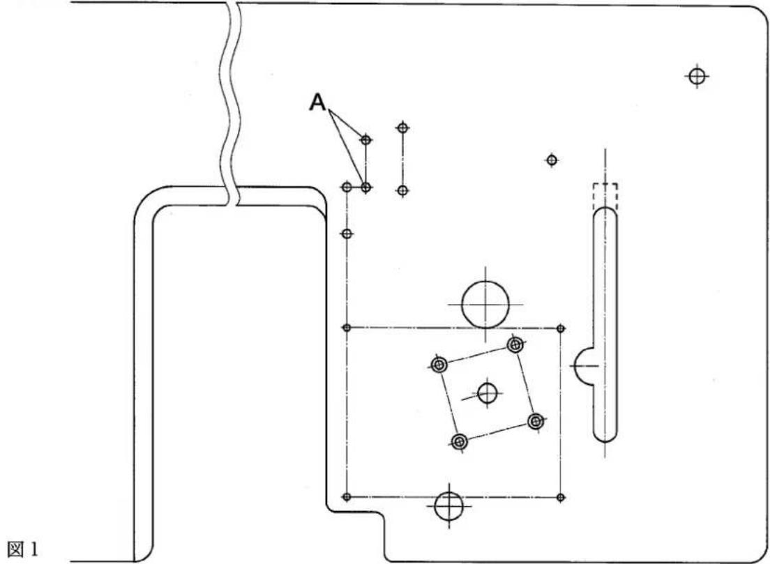
詳細の寸法は VG2700 の取扱説明書を参照してください。
1.2 ローラの取り付け方
後ローラ
ホルダ①は図1に示すAの位置に取り付けます。
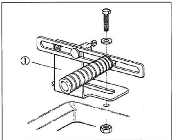
图2
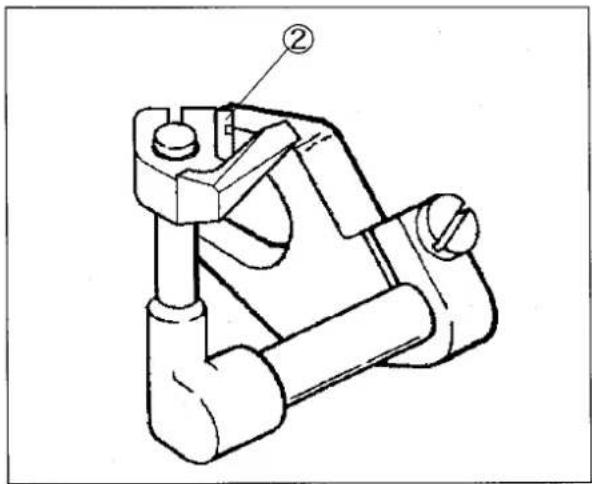
前ローラ
ブラケット②はテーブルの下面の適切な位置に取り付けます。
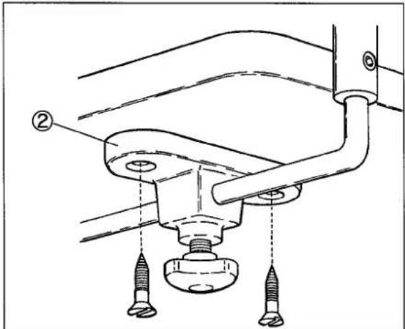
图3
2. 縫速度
このミシンの最高縫速度は5500rpm、常用縫速度は5000rpmです。
但しプーラ付の機種は最高縫速度 5000rpm、常用縫速度 4500rpm です。
新しいミシンを使用するときは、最初の200時間(約1カ月)は4400rpm程度で使用すると、ミシンを良好な状態で長期間使用することができます。
3. 正しい使い方
注意
作業を行う前に、必ずモータの電源を切り、モータの回転停止を確認してください。
3.1 糸の通し方

糸が通してある場合は、縫製用の糸を結んでください。
糸が通っていない場合は、この糸通し図(図5)を見て正しく通してください。
☆針糸
糸の結び目を針の手前まで引き出し、いったん結び目を切り落としてから改めて針に通し直してください。
左針の針糸が必ず一番奥になるように図5を見て正しく通してください。
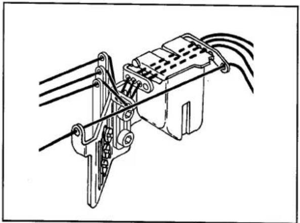
natural_image
Technical line drawing of a mechanical assembly with wires and components (no text or symbols)薄物縫製時、針糸を締めたいとき図4のように糸を通してください。
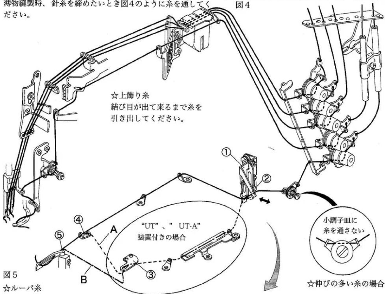
☆ルーパ糸
結び目が出てくるまで糸を引き出してから、先端をハサミで切り落としてください。
(注) “UT” 、” UT-A” 装置付きの場合のルーパ糸の通し方
- 標準は図Aのように、ルーパ糸緩メ③よりルーパ糸道(左)④へ糸を通してください。
* 綿糸やテトロン糸など伸びの無い糸のときは、図Bのようにルーパ糸緩メ③より直接ルーパ⑤へ糸を通してください。
(注)カム糸道板①のレバー②を引くと糸通しが簡単に行えます。
糸を通した後は、レバー②を押してカム糸道板①を元の位置に戻してください。
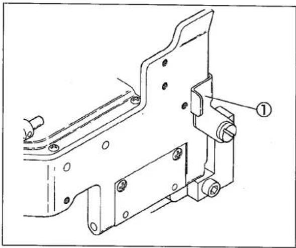
3.2 前開キカバーの開閉

前開キカバーを開けるときは、カバー固定板①を右へ回してから開けてください。
natural_image
Technical line drawing of a mechanical bracket assembly (no text or symbols)图6
3.3 吸込管の調節

吸引力はハンドバルブ②で調節します。
吸引力は切り屑を吸込む最低の圧力にしてください。
吸引力が強すぎますと、薄い生地の場合身頃も吸込まれるおそれがありますので注意してください。
メス幅を変えた場合、止ネジ③を緩めて吸込管の位置を調節してください。
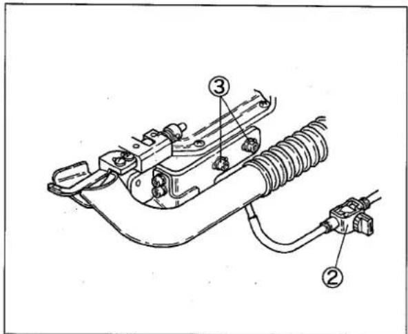
图7
注意
作業を行う前に、必ずモータの電源を切り、モータの回転停止を確認してください。
4.1 針糸調子
針糸道の位置
各針糸道の標準の位置が図に示されています。
止ネジの中心を針糸道台④の下記の線に合わせてください。
右の針糸道①上の線
中央の針糸道②中の線
左の針糸道③下の線
針糸道を下げると針糸が緩み、上げると針糸が締まります。
針糸受ヶの位置
針糸受ヶ⑤の標準の位置は針糸繰り糸道⑥が最も下がったとき、針糸繰り糸道⑥の糸穴の中心から針糸受ヶ⑤の上面まで4mmです。
針糸のループを大きくする場合や伸びやすい糸を使用される場合は、止ネジ⑦を緩め、針糸受ヶ⑤を上げ、針糸のループを小さくする場合は、針糸受ヶ⑤を下げてください。
4.2 ルーパ糸調子
カム糸道の位置
カム糸道板の合マーク⑧より、カム糸道(左)⑨及びカム糸道(右)⑩の糸穴中心は3mm下にあるのが標準位置です。
ルーパ糸をゆったり出したいときは、カム糸道(左)⑨及びカム糸道(右)⑩の止ネジを緩め、糸道を下の方向に動かし、ルーパ糸を締めたいときは上の方向に動かします。
注意
伸びの多い糸の場合は、カム糸道(左)⑨及びカム糸道(右)⑩を最も下げてください。
小調子皿⑪には糸を通さないでください。

图8
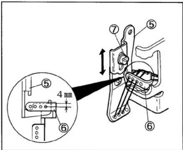
图9
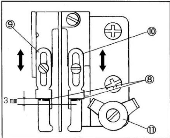
图10
4.3 針の高さの調節
(1) 針を針止メの左針取り付け穴にセットする。
(2) ルーパがルーパ台の奥まで挿入されていることを確認する。
(3) ルーパの先端が左針の中心にくるまでハンドホイールを回す。
(4) ルーパの先端が針穴の上端より 1.0~1.3 mm 上を通るように、針棒抱キ止ネジ①を緩め、針棒を上下させる。
(5)針棒抱キ止ネジ①を締め付ける。針が針板の針落ち穴の中心に落ちることを確認する。
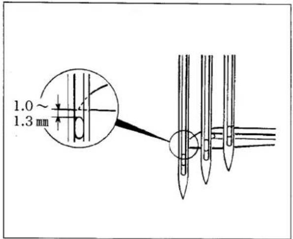
图11
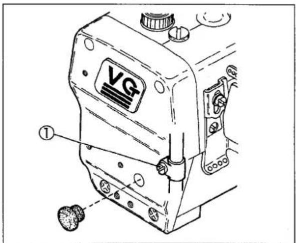
图12
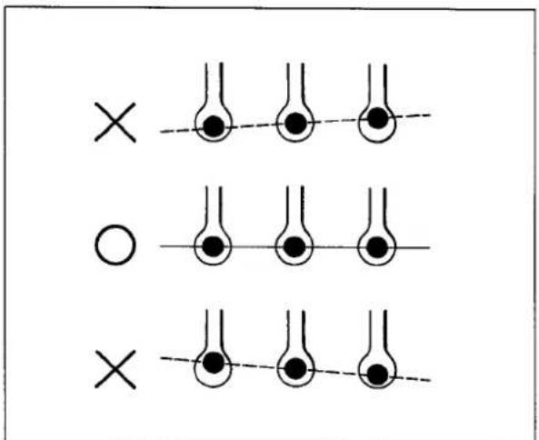
图13
4.4 針とルーパの前後位置
(1) ルーパの先端④が左針⑤の中心にくるまでハンドホイールを回す。
(2) 左針⑤の背面とルーパ先端のすき間が0.1~0.2mmになるようにルーパ台の止ネジ③を緩め、ルーパ台を前後に調節し、止ネジ③を締め付ける。
注意
止ネジ③を締め付けるときに、ルーパの前後位置が移動する場合があります。止ネジ③を締め付けた後で、再度ルーパの前後位置を確認してください。
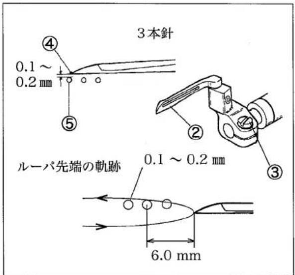
图14
4.5 針と針受ケ(後)の調節
針受ケ(後)の高さ
(1)針が上昇し、ルーパ①の先端が左針の中心にくるまでハンドホイールを回す。
(2) 止ネジ②を緩める。
(3)針受ケ(後)③は左針④の先端が針受ケ(後)の稜線⑤より0~0.3mm下にくるようにする。
(4) 止ネジ②を仮締めする。
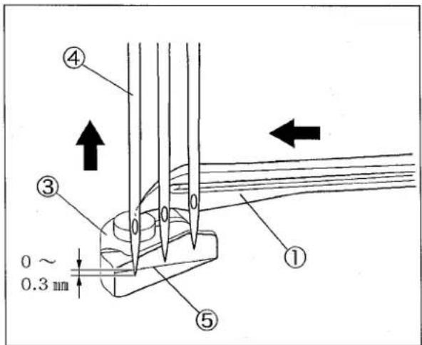
图15
natural_image
Technical line drawing of a mechanical clamp or bracket component (no text or symbols)图16
針受ヶ(後)の前後位置
ネジ①②を緩めて、下記の条件を満足するように調節する。
(1) ルーパ③が右から左へ動くとき、ルーパの先端が右針の中心と合うとき針受ケ(後)④で右針を押して針とルーパ③のすき間が0~0.05mmにする。
(2)針が上昇して、左針⑥の針穴の上側と針受ケ(後)④の稜線⑤が一致するとき針と針受ケ(後)④のすき間が0.2~0.5mmになる。
(3) ルーパが左針⑥の中心に合うとき、左針⑥を針受ケ(後)④に押し付けたとき針とルーパ③のすき間が0.1 mmになる。
調節後ネジ①②をしっかり締める。
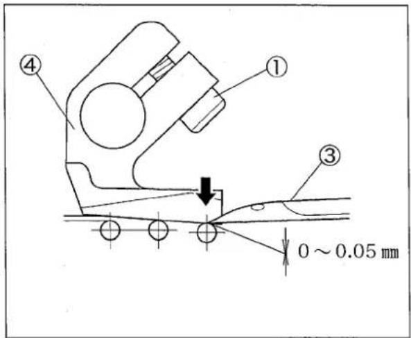
图17
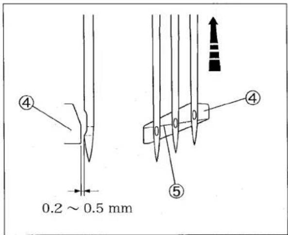
图18
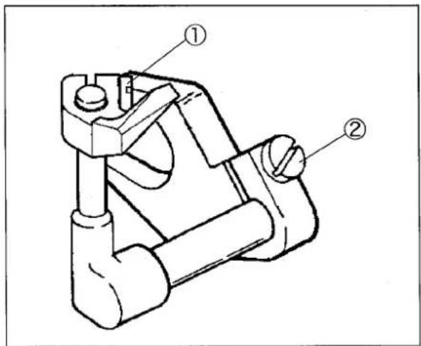
图19
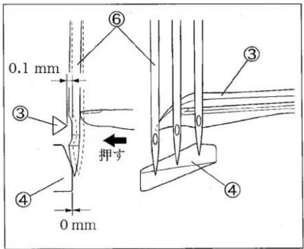
图20
4.6 針と針受ケ(前)の調節
(1)ルーパの先端の右針の中心に合わせる。
ネジ②を緩める。針受ケ(前)を上から見て針を結ぶ直線と平行になるようにする。
ネジ②を締める。
(2)ルーパの先端が左針の中心にくるまでハンドホイールを時計方向へ回す。
(3)止ネジ②を緩め、針の先端から2.5~3.0mm上の位置に針受ヶ(前)①の段部がくるように高さを調節する。
(4)止ネジ②を締め付ける。
(5)止ネジ②及び④を緩め、右針及び左針と針受ケ(前)①とのすき間が0.3~0.4mmになるように調節する。
(6)止ネジ②及び④を締め付ける。
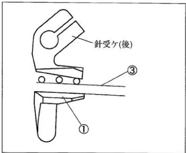
图21
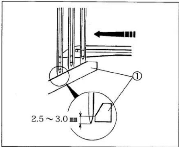
图22
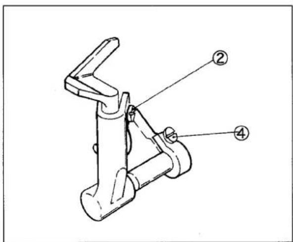
图23
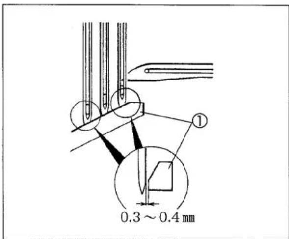
图24
4.7 ローラの調節
○前ローラ①、後ローラ②は身頃を軽く広げたサイズに合わせて各々適切な位置にセットしてください。
○前ローラは前後と上下に調節できます。標準は針板より高くします。
後ローラは前後に調節できます。また上下は2段階に変更できます。標準は上の方を使用します。
下ローラ⑧は左右に調節できます。
○ゴムの左右位置はゴムの左端が左針より少し左側にくるように前ローラ①のゴムガイド③、下ローラガイド④をゴムの右端に合わせます。
○ゴムガイド⑤はゴムの右端に軽く沿わせ、押エに当たらない程度にできるだけ近づけてください。調節は止ネジ⑥及び⑦を緩めて行います。
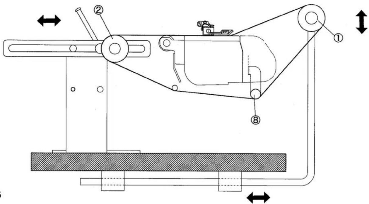
图25
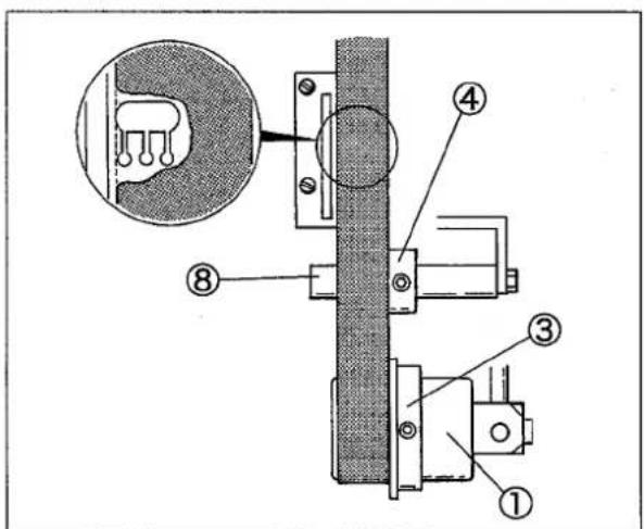
图26
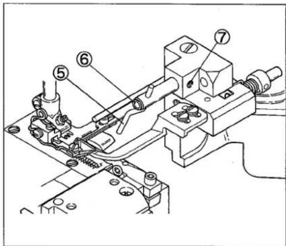
图27
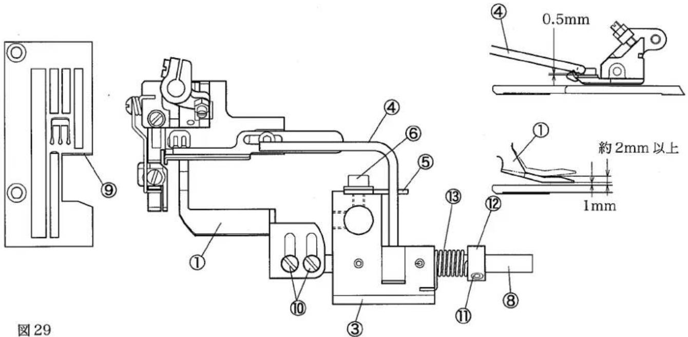
4.8 布押工の調節
布押工の高さ
- 送りが最も上がったとき、布押エ①の裏面が送りの上面と平行で、送り上面と軽く接触するように、止ネジ②を緩めて布押エ軸ブラケット③の高さを調節してください。
- 送りが最も上がったとき、押エの下に縫製素材のゴムをセットし、押エ右端の上面とガイド棒④とのすき間を0.5mmにしてください。
調節はガイド棒ストッパ⑤の止ネジ⑥を緩めて行います。
3.縫製素材のゴムを取り外し、布押エ①の裏面と針板上面とに1.0mmのすき間を設けてください。
調節はガイド棒④の止ネジ⑦を緩めて、布押エ軸⑧を回して行います。
4.針棒を最上点にして、押工を上げたとき、布押エ①が送り上面より約2.0 mm以上上がることを確認してください。
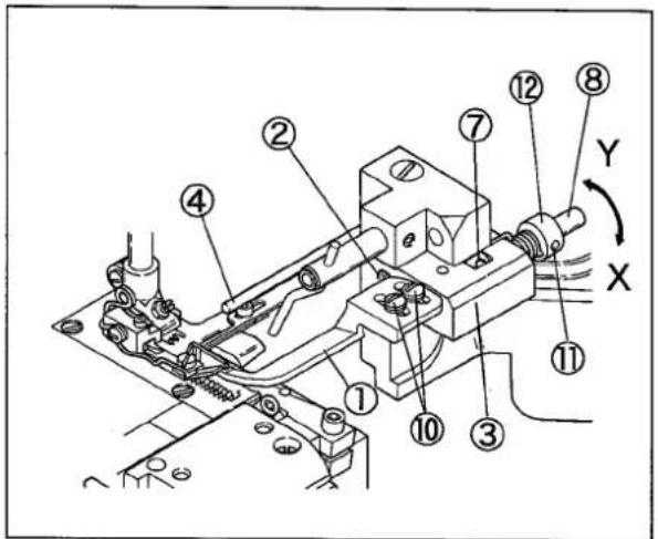
图28
布押工の前後・左右位置
- 布押エ①の先端を針板の前面⑨に合わせてください。止ネジ⑩を緩めて調節します。
- 布押エ①の左右位置は前送りの上にあって、できるだけ上メスに接近させてください。止ネジ⑦、⑪を緩めて布押エ軸⑧を左右に動かして調節します。
布押工の圧力
布押エ①の圧力を強くするときは、カラー⑫の止ネジ⑪を緩めて、カラーをX方向に回してください。圧力を弱くするときは、カラー⑫をY方向に回してください。
バネ⑬の圧力は騒音が出ない程度に、できるだけ弱くしてください。
5. メス装置の調整
注意
作業を行う前に、必ずモータの電源を切り、モータの回転停止を確認してください。
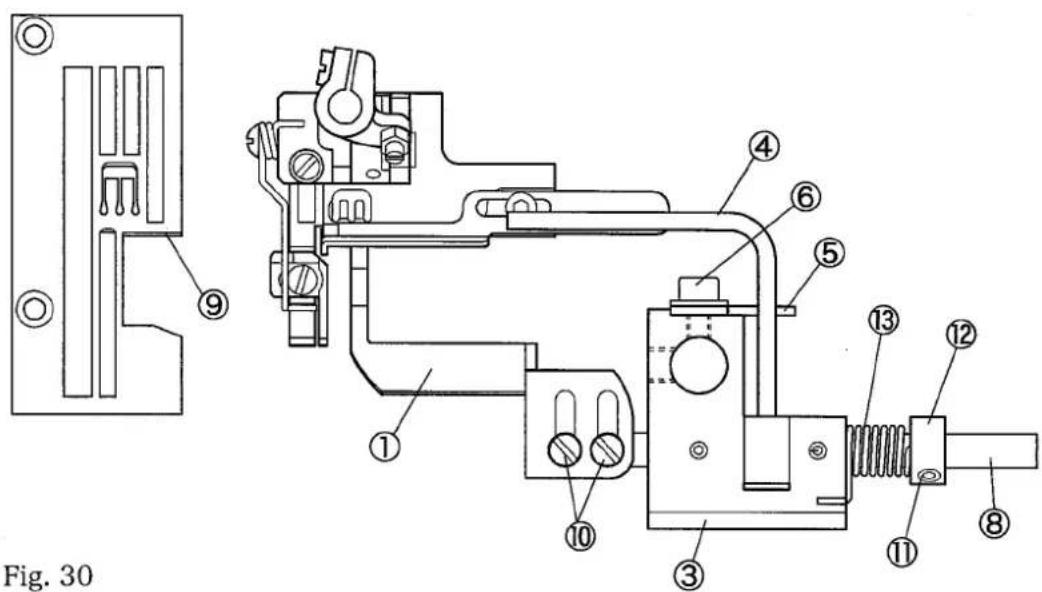
5.1 メス幅(布切断位置)の調節
- 当テ定規を取り外す。
2.下メス台の止ネジ①を緩める。
3.カラー(右)の止ネジ②を緩める。
4.下メス台を希望するメス位置にする。
5.下メス台の止ネジ①を締め付ける。 - カラー(左)の止ネジ③を緩め、止ネジ④を回して適当なバネの圧力を加える。
- カラー(右)の止ネジ②を締め付ける。
- カラー(左)の止ネジ③を締め付ける。
- 止ネジ④を緩まない程度に締め付ける。
注意
定期的に、注油孔⑤に少量の油を差してください。
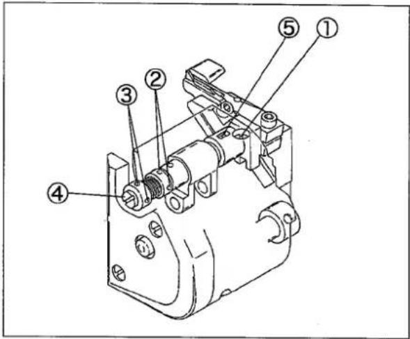
图30
5.2 下メスの取り外し、取り付け
取り外し方
- 当テ定規を取り外す。
- カラー(右)の止ネジ②を緩める。
- 上メス台⑥を右の方向に引っ張り、上メスと下メスとにすき間を設ける。
- カラー(右)の止ネジ②を仮止めする。
- 下メスの止ネジ⑦を緩めて下メス⑧を下方向に抜く。
取り付け方
- 下メス⑧の刃先を針板上面と同一にして、止ネジ⑦を締め付ける。
- カラー(右)の止ネジ②の仮止めを緩める。
(バネの力で上メスは下メスとかみ合う) - 上メスと下メスの間に糸を入れ、ハンドホイールを回してメスの切れ味を確かめる。
- 上メス⑨の先端から8mmの位置を下メス⑧の上面に合わせて、カラー(右)の止ネジ②を締め付ける。
- もう一度、メスの切れ味を確かめる。
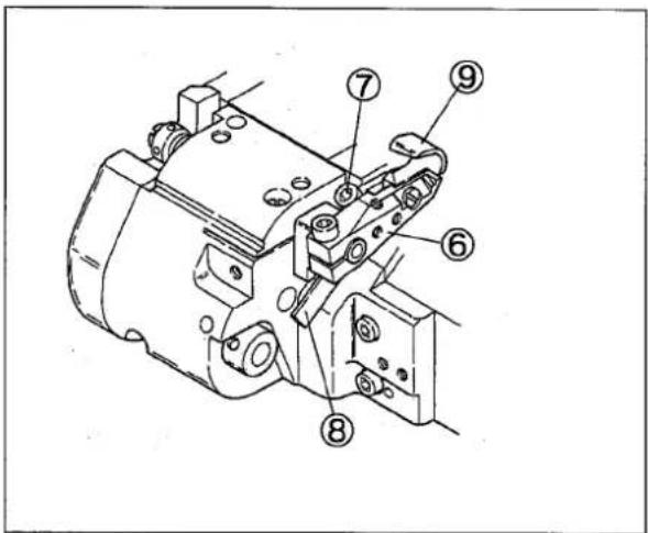
图31
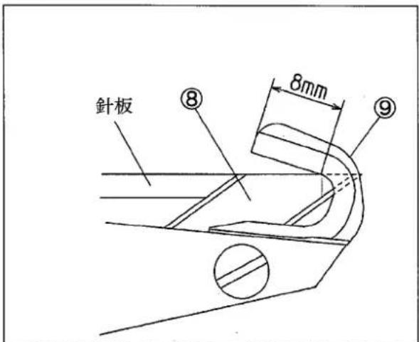
图32
5.3 上メスの取り外し、取り付け
取り外し方
- 上メス台の止ネジ①を緩めて、上メス台②を取り外す。
- 上メスの止ネジ③を緩めて、上メス④を取り外す。
取付け方
- 上メス④を止ネジ③で上メス台②に取り付ける。
- 上メス④の端面を上メス軸⑤の端面と同一にして、止ネジ①を仮止めする。
- 上メス④が最も下がったとき、上メス台②を動かして上メス先端を下メス⑥の上面より0.5mm上の位置にして、止ネジ①を締め付ける。
- カラー(右)の止ネジ⑦を緩めると、バネの力で上メス④と下メス⑥がかみ合います。
- 上メスと下メスの間に糸を入れ、ハンドホイールを回してメスの切れ味を確かめる。
- カラー(右)の止ネジ⑦を締め付ける。
- もう一度、メスの切れ味を確かめる。
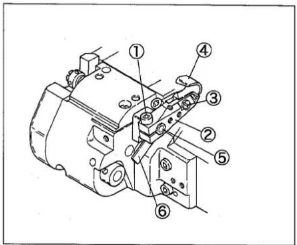
图33
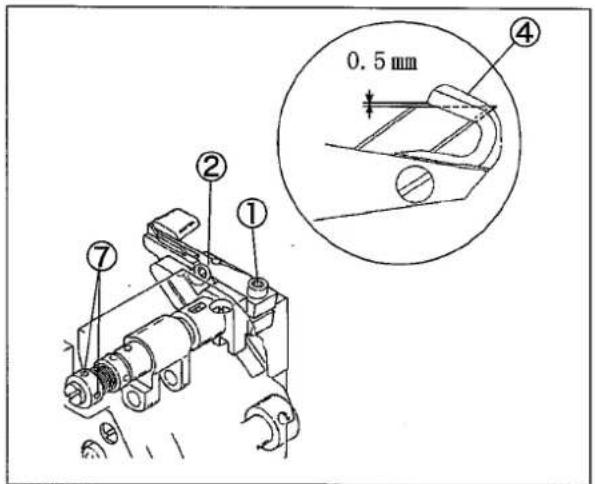
图34
5.4 下メスの砥ぎ方
上メスは超硬合金製ですから1年ぐらいは研ぎ直す必要はありません。この間にメスの切れ味が悪くなったときは、下メスを砥ぎ直して下さい。
研ぎ直すときは、図を参考にして正確に砥いでください。そのときは、必ず水を用意して下メスを冷やしながら行ってください。
上メスを砥ぎ直すときは、普通のグラインダでは砥げませんから、常に予備の上メスを用意していただき、砥ぎ直しを購入代理店または当社に依頼してください。

图35
5.5 上メスのストロークの調節
出荷時の上メスのストロークは5.0 mmに調節してあります。上メスのストロークを変更するときは、下記の順序で行ってください。
- ブラケット横カバー①を取り外す。
- ストッパ②の止ネジ③を緩める。
- ストッパ②をX方向へ動かすと、ストロークが大きくなり、Y方向へ動かすと小さくなります。
(上メスと下メスのかみ合いを再調節してください。)
- 止ネジ③を締め付ける。
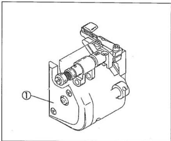
图36
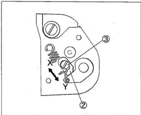
图37
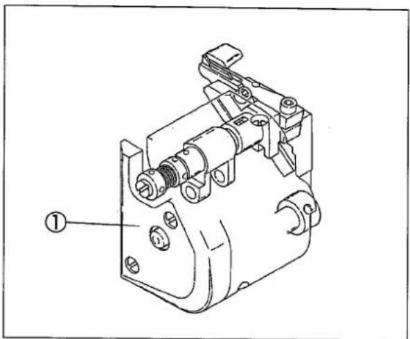
5.6 下メス台ブラケットの取り外し
1.針板を取り外す。
2. 下メス台プラケット①の止ネジ②(3個)を取り外す。
3. ハンドホイールを手で回し、針棒を最下点にする。
4. 下メス台ブラケット①のノックピン③をベッドから抜く。
5. 下メス台ブラケット①の上部を手前に少し傾けるようにしながら、上メス駆動腕④より上メスリンク(短)⑤を取り外す。
注意
下メス台ブラケット①はベッドに接近した位置で、左横方向に動かすこと。
(角駒⑥が角駒ガイド⑦より外れないようにする為。外れたときは、角駒曲面をミシン側にして角駒⑥を角駒ガイド⑦に差し込む。)
- 上メス駆動腕④を送り上下軸⑧より取り外す。このとき、上メス駆動腕④に結んでいる油芯⑨も一緒に取り外す。
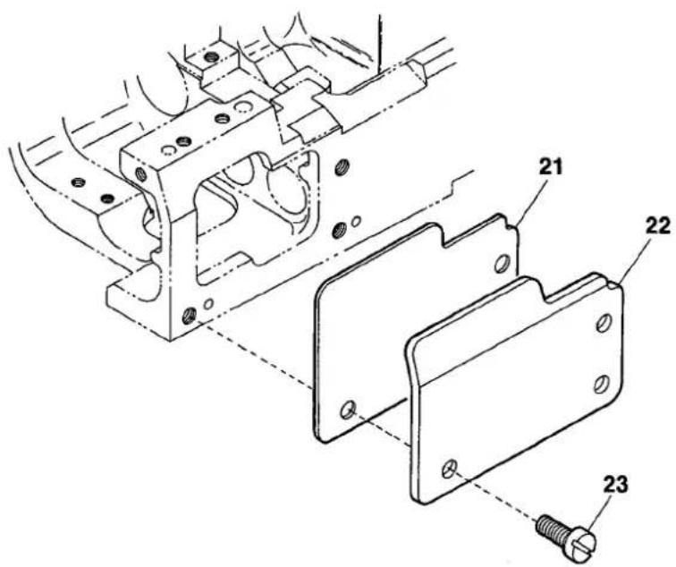
- ベッドカバー⑩及びパッキン⑪を止ネジ⑫でベッドに取り付ける。
- 補助ブロック⑬を針板台⑭に取り付ける。
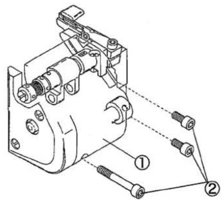
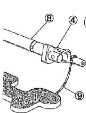
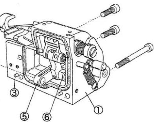
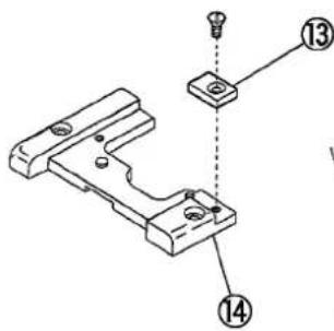
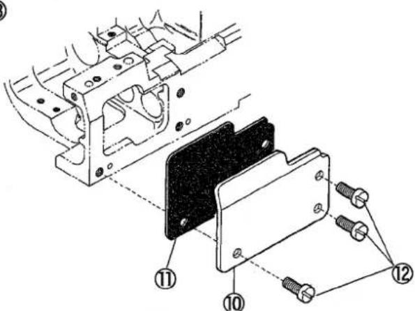
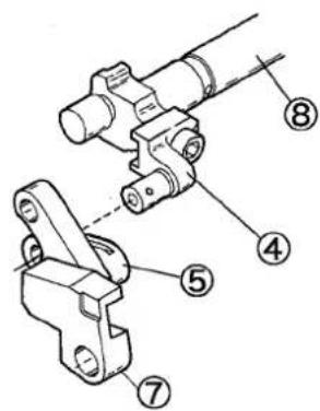
图38
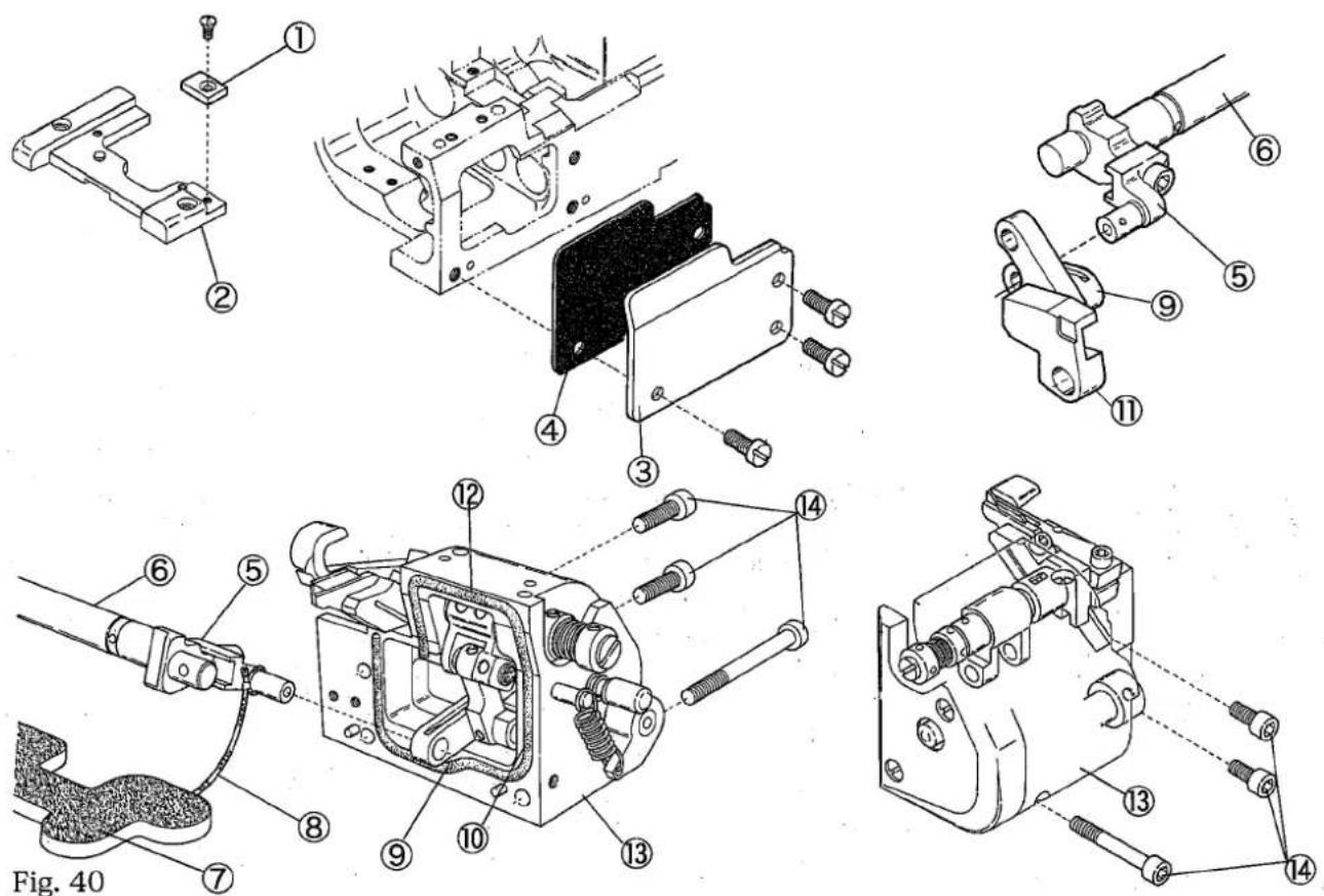
5.7 下メス台ブラケットの取り付け
1.針板を取り外す。
2. 補助ブロック①を針板台②から取り外す。
3. ベッドカバー③及びパッキン④を取り外す。
4. 上メス駆動腕⑤を送り上下軸⑥に取り付ける。
上メス駆動腕⑤に結んでいる油芯⑧を送り台の下にあるフェルト⑦の下に挟み込む。
注意
上メス駆動腕⑤が最も手前に振り出したとき、油芯⑧が引っ張られないように注意してください。
- 上メス駆動腕⑤を最も振り出した位置にしておく。
- 上メスリンク(短)⑨を上メス駆動腕⑤に連結する。
このとき、角駒⑩を角駒ガイド⑪の先端より少し出しておくこと。また、角駒⑩が角駒ガイド⑪から外れないように注意すること。
- ブラケットパッキン⑫を下メス台ブラケット⑬の溝に置き、下メス台ブラケット⑭を止ネジ⑭で取り付ける。ブラケットパッキン⑫がズレないように注意する。
- 下メスの位置を調整し、上メスのかみ合いを確認し、上メスバネの圧力を調節する。
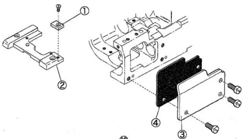
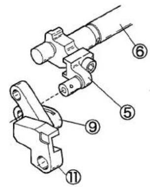
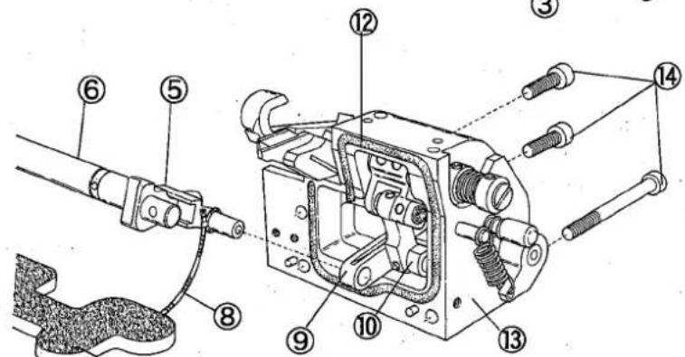
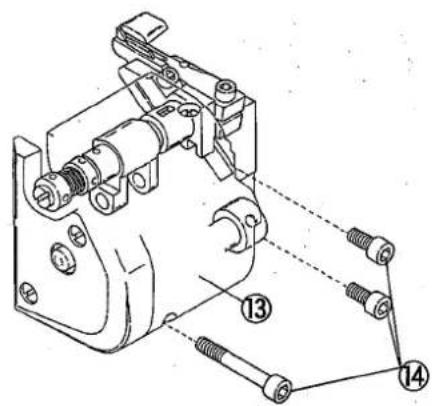
图39
6. 仕様
| 機種 | VG2735-31-8F-R |
| 名称 | 右メス機構付き、輪状平織ゴム付け用扁平縫いミシン |
| 外観寸法 | 445(長)×220(幅)×405(高)mm |
| 筒外周 | 370mm |
| 重量 | 45kg(ローラ関係は含まず) |
| 縫目型式 | ISO 406,407,602,605 |
| 用途 | ニット、メリヤス等の輪状平織ゴム付け(縫製可能ゴム幅 最大 35mm) |
| 縫速度 | 最高每分 5500rpm (プーラ付は5000rpm) |
| 縫目長さ | 1.4~3.6mm縫い目数 1吋間7~18針30mm間8~21針 |
| 使用針 | UY×128GAS #9~#14(標準#10) |
| 針のストローク | 33mm |
| 押エ上り量 | (針幅5.6mmの場合)上飾りなし:7.5mm |
| 送り調節方法 | つまみ調節ネジ(マイクロアジャスト可) |
| 差動送り比率 | 1:0.9~1:1.4(標準)1:0.9~1:1.8(最大正差動使用時は縫い目長さを2.5mm以下のこと)1:0.6~1:1.1(リンクの位置変更により可能) |
| 差動送り調節方法 | アジャスタにより可能(マイクロアジャスト可能)(外部からレバーを上下する事により回転中も調節可能) |
| 潤滑方法 | トロコイドポンプによる自動給油 |
| 潤滑油 | ヤマトSFオイル28 |
| 貯油量 | 800cc |
| 据付け方法 | テーブル上乗せ式 |
WARNING
ALWAYS turn OFF the motor switch and check that motor stops before adjustment.
1.1 Table cutting diagram
Table top type
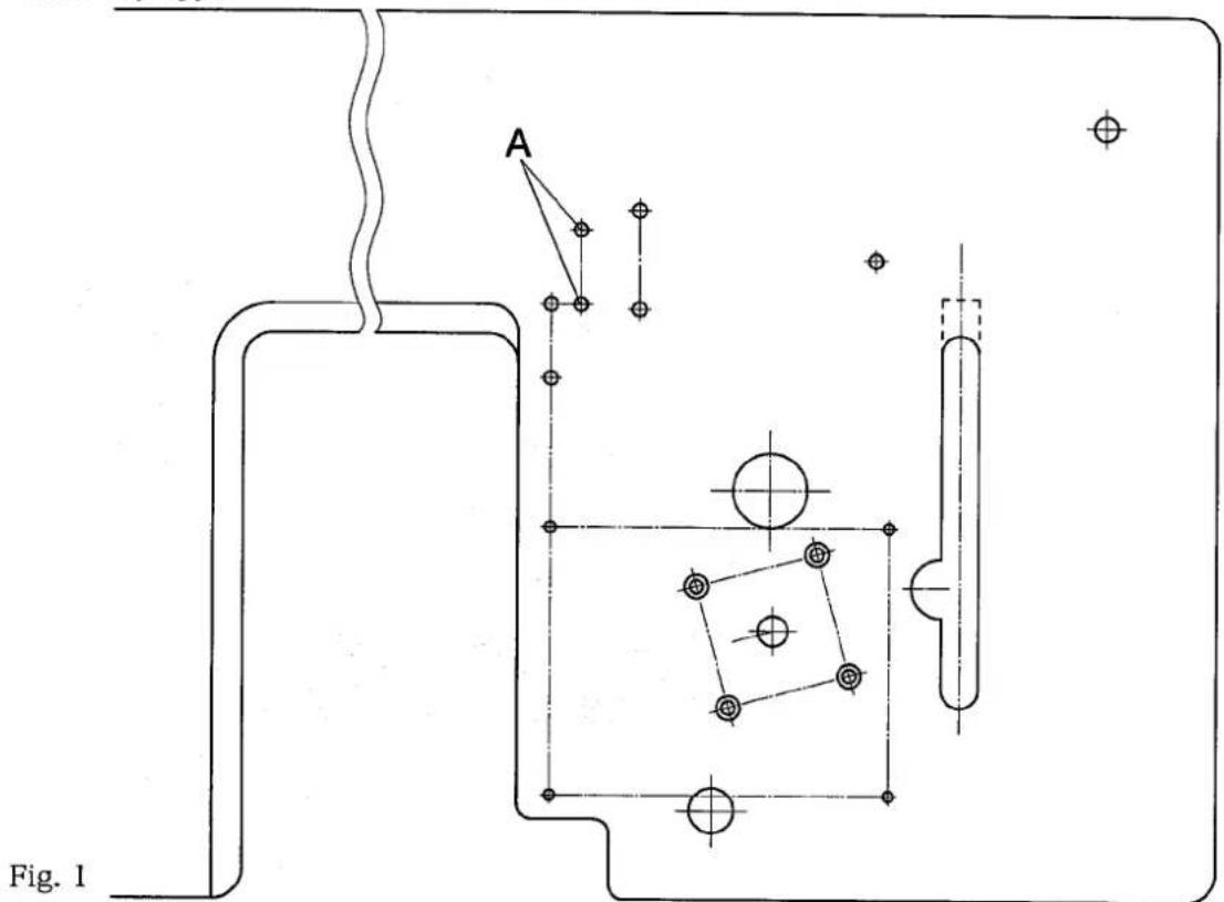
Refer to the instruction manual for VG2700 model for each dimension.
1.2 Roller
Tension roller:
Fix the tension roller holder① on the position A in Fig. 1.
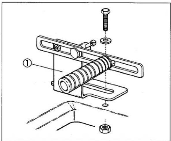
Fig. 2
Elastic tape front roller:
Fix the brackets② on the back of a machine table properly.
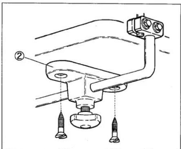
Fig. 3
2. Sewing speed
The highest sewing speed of this sewing machine is 5500rpm, and the sewing of using regularly speed is 5000rpm.
However, the highest sewing speed of with puller model is 5000 rpm, and the sewing of using regularly speed is 4500 rpm.
When a new sewing machine is used, the first 200 hours (about one month) can excellently use the sewing machine for a long term by using it by about 4400 rpm.
WARNING
ALWAYS turn OFF the motor switch and check that motor stops before adjustment.
3.1 Threading

When had been threaded, knot the preset thread and new one together to rethread.
When not threaded, see this threading chart(Fig. 5) to thread correctly.
☆Needle thread
Pull thread until it reaches the front of the needles. And, cut off knots just before needle eye to rethread.
Thread needle thread for left needle as it is in the inmost recess as illustrated (fig. 5).
Tighten needle thread, when light material is sewing.
The following thread as shown in a right Fig. 4.
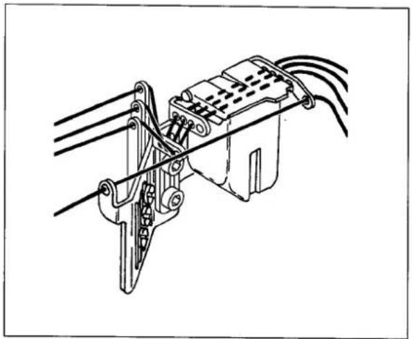
natural_image
Technical line drawing of a mechanical clamp or bracket assembly (no text or symbols)Fig. 4
☆ looper thread
Pull thread until the knot is out.
Then, cut off the knot.
(Notice) Threading for sewing with "UT" or "UT-A".
* For standard type, looper thread⑤ through looper thread eyelet(left)④.
* For less stretchable threads, looper thread
⑤ without threading looper eyelet (left)④.
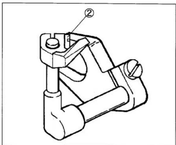
Note: For easy threading, pull the lever② in the thread take-up eyelet holder①.
After threading, restore the holder① to the operating position with the lever②.
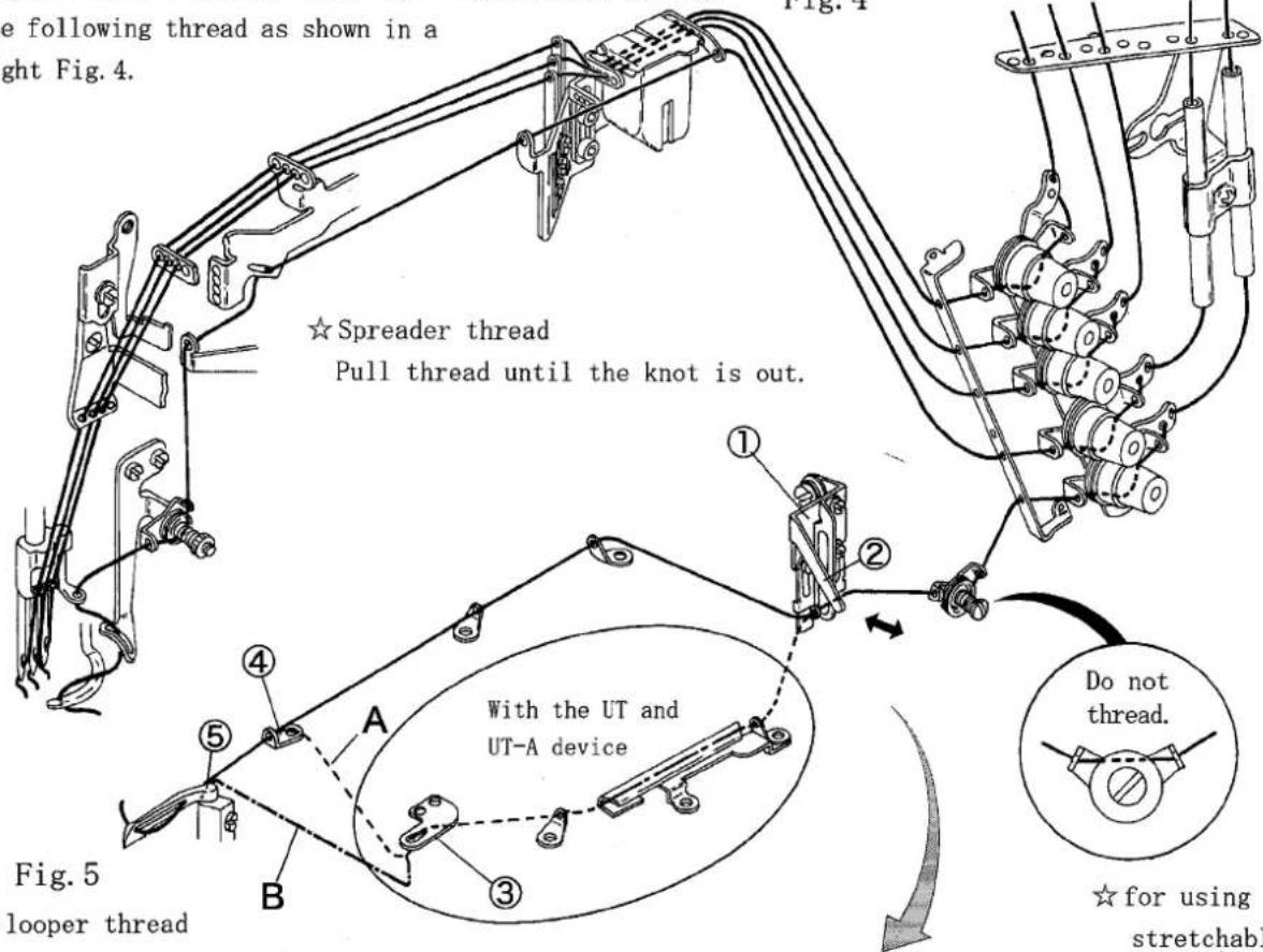
3.2 Opening and closing of front cover

Before opening the front cover, swing the cover fixing plate① to the right.
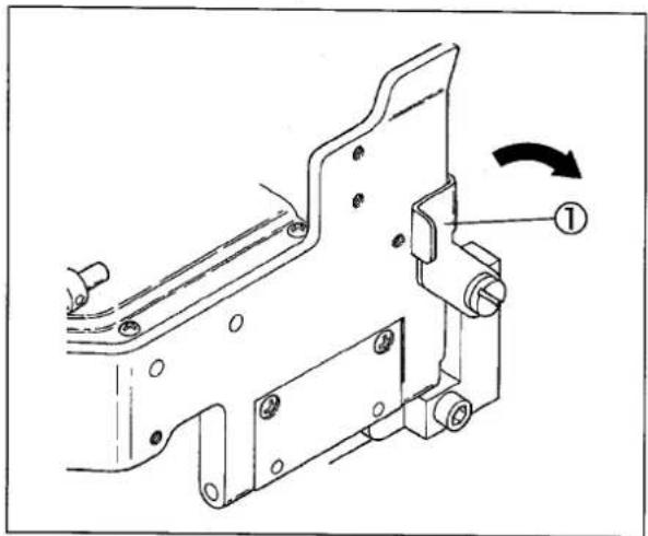
Fig. 6
3.3 Adjustment of suction pipe

The power of suction can be adjusted by hand valve②. Set the power of suction at the minimum pressure to be able to suck the waste only.
Pay attention for the light weight fabrics, the material of main parts may be pulled in if setting at too high pressure.
When the trimming width is changed, adjust the position of suction pipe by loosening screws③.
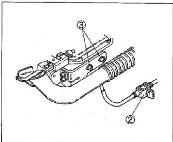
Fig. 7
4. Adjustments of sewing machine

WARNING
ALWAYS turn OFF the motor switch and check that motor stops before adjustment.
4.1 Needle thread tension
Needle thread eyelet position
The standard positions of each needle thread eyelet are shown in the figure.
Care should be taken so that the center of the screws is aligned eyelet bracket④.
- right needle thread eyelet①: top line
- middle needle thread eyelet②: middle line
- left needle thread eyelet③: bottom line
To tighten needle thread, raise the needle thread eyelet.
To loosen, lower the eyelet.
Needle thread guide position
The standard position is that the distance is 4.0mm from the center of the eye in the needle thread take-up ⑥ to the top of the needle thread guide ⑤ when the take-up ⑥ is at its bottom.
To make needle thread loop bigger or when stretchable thread is used, loosen the screw⑦ and raise the needle thread guide⑤.
To make the loop smaller, loosen the screw⑦ and lower the guide⑤.
4.2 Looper thread take-up
Thread take-up eyelet position
The standard position is that the eye centers of the thread take-up eyelets(left)⑨ and (right)⑩ are 3mm lower than the lines⑧ on the thread take-up eyelet holder.
To loosen, loosen the screws of the eyelets and lower the eyelets⑨,⑩.
To tighten, loosen the screws of the eyelets and raise the eyelets⑨,⑩.
NOTE
For using stretchable threads, move the eyelets ⑨ and ⑩ to their bottom.
Do not thread to the tension disc⑪.
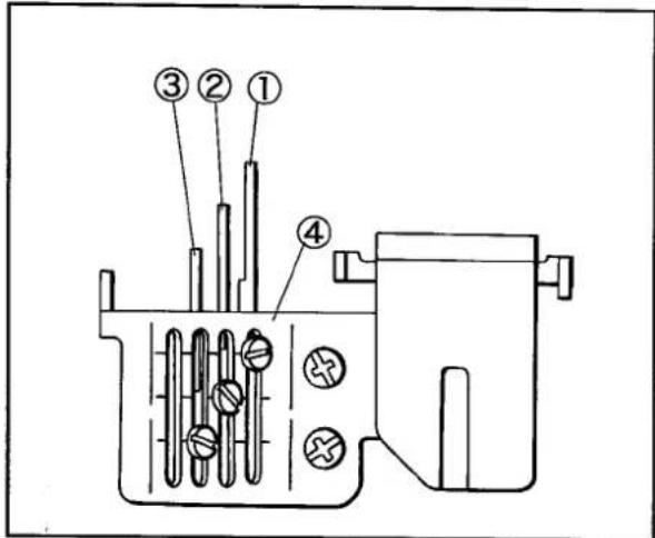
Fig. 8
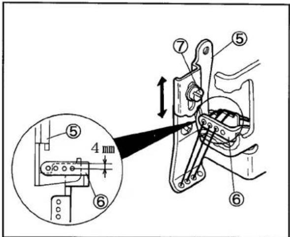
Fig. 9
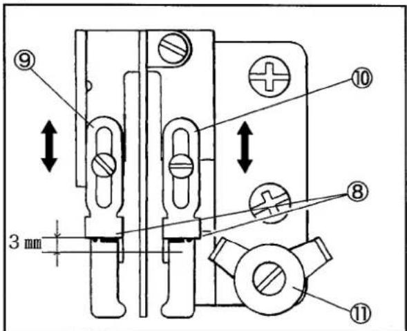
Fig. 10
4.3 Height of needle
(1) Install the needle to the left hole in the needle clamp.
(2) Check the looper is inserted into the looper holder fully.
(3) Turn the handwheel until the looper tip meets the center of the left needle.
(4) Loosen the screw ① of the needle bar bracket and move the needle bar up and down. Adjust the looper tip to pass 1.0 - 1.3 mm above the top of the needle eye.
(5) Tighten the screw① securely. Check that the needles drop in the centers of the needle holes of the stitch plate respectively.
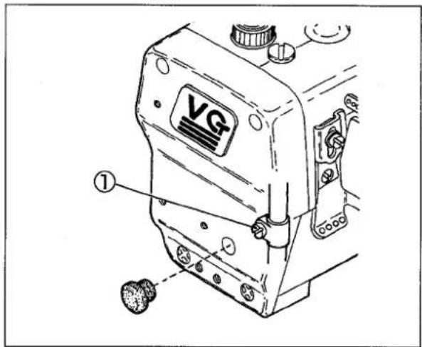
Fig.12
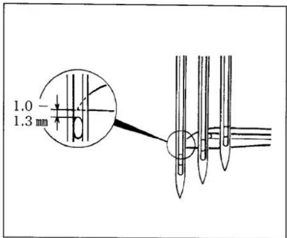
Fig.11
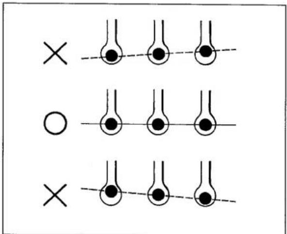
Fig.13
4.4 Front-and-rear position of needle and looper
(1) Turn the handwheel until the looper tip④ meets the center of the left needle⑤.
(2) Loosen the screw③ and move the looper holder back and forth. Make the clearance between the back of the left needle⑤ and the looper tip to 0.1 - 0.2 mm. Then, tighten the screw③ securely.
NOTE
When tightening the screw③, front-and-rear position of the looper may be shifted. Recheck the position after tightening it.
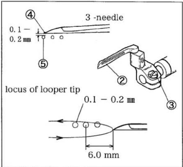
Fig.14
4.5 Needle and needle guard (rear)
Height of needle guard(rear):
(1) Rotate the handwheel until the needle is raised and the looper ① tip comes in the center of the left needle.
(2) Loosen the screw②.
(3) Adjust the needle guard(rear)③ so that the left needle ④ tip is 0 - 0.3 mm below the ridge line⑤.
(4) Tighten the screw② temporarily.
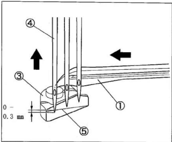
Fig.15
natural_image
Technical line drawing of a mechanical clamp or bracket component (no text or symbols)Fig.16
Front-and-rear position and angle between needle guard (rear) and needle:
Loosen the screws① and ② to adjust them with keeping three conditions as below.
(1) When the looper③ moves from the right to the left, and the looper ③ tip meets the right needle, the needle guard(rear)④ pushes the right needle to make the clearance between them to 0 - 0.05 mm.
(2) When raising the needles, and the upper needle eye of the left needle⑥ is aligned with the ridge line ⑤ on the needle guard(rear)④, make the clearance between them to 0.2 - 0.5 mm.
(3) When the looper ③ tip comes in the center of the left needle ⑥, and the left needle ⑥ is pushed on the needle guard (rear) ④, make the clearance between the looper ③ and the left needle ⑥ to about 0.1 mm.
After adjusting, tighten the screws① and ② securely.
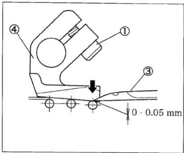
Fig. 17
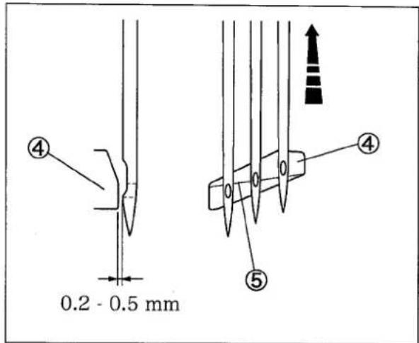
Fig. 18

Fig.19
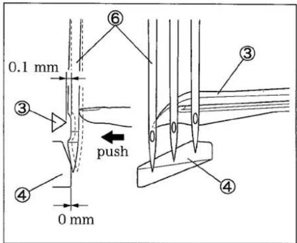
Fig. 20
4.6 Needle and needle guard (front)
(1) When the looper tip comes in the center of the right needle, loosen the screw②. Place the needle guard (front)① paralell to the line aligned the needles seeing from the top. Tighten the screw②.
(2) Rotate the handwheel clockwise until the looper tip comes in the center of the left needle.
(3) Loosen the screw② to adjust the needle guard(front)
① so that each needle tip is 2.5 - 3.0 mm below the corner on the needle guard(front)①.
(4) Tighten the screw②.
(5) Loosen the screws ② and ④. Make the clearance between the needle guard(front) ① and the right needle or the left needle to 0.3 - 0.4 mm respectively.
(6) Tighten the screws② and ④ securely.
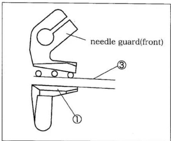
Fig. 21
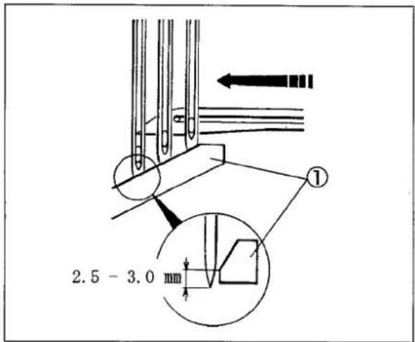
Fig. 22
Fig. 23
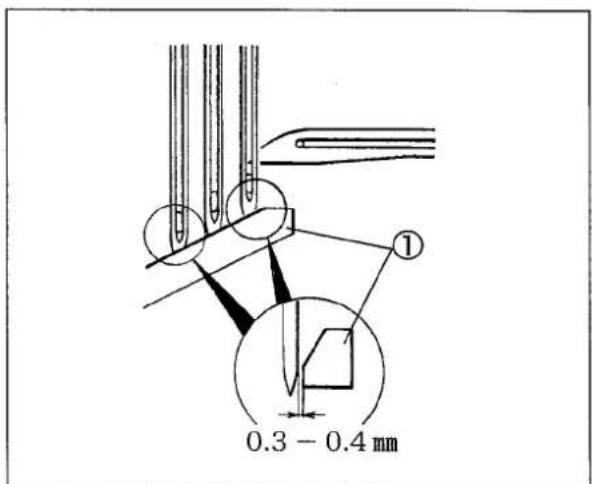
Fig. 24
4.7 Adjustment of rollers
○Adjust the position of the front roller① and the rear roller② according to the size of fabric to be sewn.
○Front roller ①can be adjusted up and down back and forth. Standards position is higher than the stitch plate.
Rear roller② can be adjusted back and forth. Moreover, up and down is revocable in two stages. The standard uses above position. Lower roller⑧ can be adjusted right and left.
The right and left position of elastic tape is matched to a right edge of elastic tape by elastic tape guide③ of front roller① and lower roller guide④ so that the left end of elastic tape may come from a left needle to the left side a little.
○Apply the elastic tape guide⑤ to the right side of elastic tape and bring the guide⑤ close to the presser foot as possible without contact.
For the adjustment, loosen the screw⑥ and ⑦.
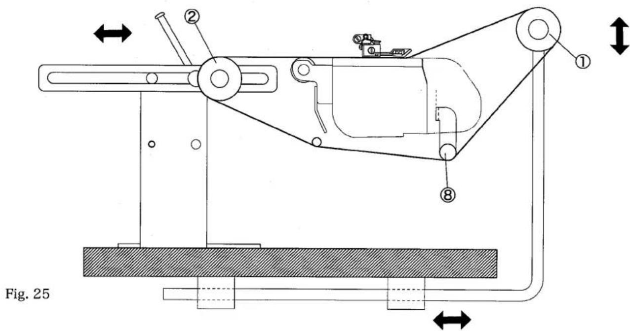
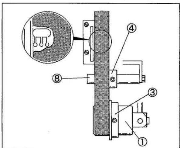
Fig. 26
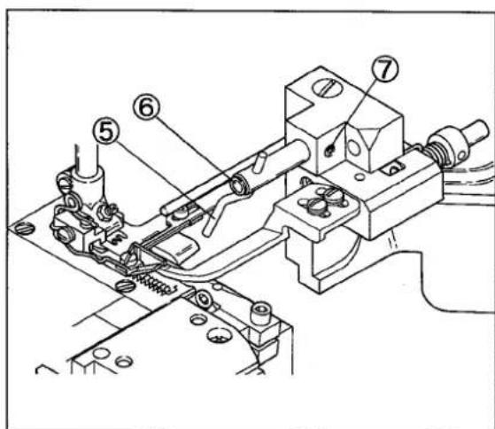
Fig. 27
4.8 Adjustment of fabric presser
Height of fabric presser
- Loosen the screw ② and adjust the height of fabric presser shaft bracket ③ to make the back of fabric presser to be parallel with the top surface of feeding dog and contact to it slightly when the feed dog is at its top dead point.
- At the highest point of feed dog movement, load the elastic tape to be sewn under the presser foot and make the clearance of 0.5mm between the top surface of right side of presser foot and the fabric presser guide bar④.
For the adjustment, loosen the screw⑥ on the guide bar stopper⑤.(Fig.30)
- Unload the elastic tape to be sewn and make the clearance of 1.0mm between the back of fabric presser① and the top surface of stitch plate.
For the adjustment, loosen the screw⑦ on the fabric presser guide bar④ and rotate the fabric presser shaft⑧.
- When the presser foot is lifted up with the needle bar being at the highest point, make sure that the fabric presser ① is lifted up 2.0mm or more from the top surface of feed dog.
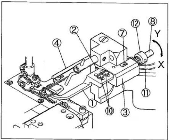
Fig.28
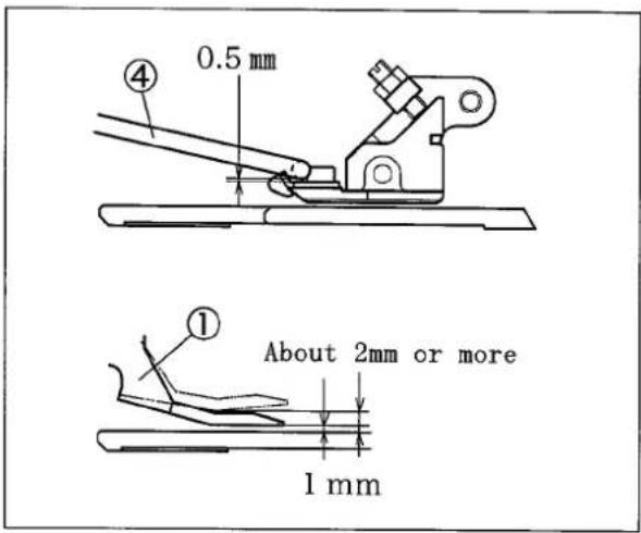
Fig.29
Position of fabric presser in front and rear, right and left
- Apply the tip of fabric presser① to the front surface⑨ of stitch plate. For adjusting, loosen the screw⑩.
- The fabric presser① should be above the differential feed dog in right and left and make it close to the upper knife as possible. Loosen screw⑦⑪, move the fabric presser shaft⑧ right and left, and adjust it.
Pressure of fabric presser
To increase the pressure, loosen the screw ⑪ on the collar ⑫ and turn the coller to the arrow X direction.
To decrease the pressure, turn it to the arrow Y direction.
Adjust the pressure of spring⑬ at lowest so long as it does not make much noise.
5. Adjustment of trimming mechanism
WARNING
ALWAYS turn OFF the motor switch and check that motor stops before adjustment.
5.1 Trimming width (Cutting position of fabric)
- Remove the edge guide.
- Loosen the screw① on the lower knife holder.
- Loosen the screw② on the collar(right).
- Set the lower knife holder as desired position according to trimming width.
- Tighten the screw① on the lower knife holder.
- Loosen the screw③ on the collar(left) and apply proper pressure of spring by rotating the screw④.
- Tighten the screw② on the collar(right).
- Tighten the screw③ on the collar(left).
- Tighten the screw④ as not be loosened.
NOTE
Supply some oil into oil hole⑤periodically.
5.2 Removing and installing the lower knife
How to remove the lower knife
- Remove the edge guide.
- Loosen the screw ② on the collar(right).
- Make the clearance between upper and lower knife by pulling the upper knife holder⑥ to the right.
4.Tighten the screw ② on the collar(right) temporarily. - Loosen the screw⑦ on the lower knife and remove the lower knife⑧ downward.
How to install the lower knife
- Align the tip of blade of the lower knife⑧ with the top surface of stitch plate and tighten the screw⑦.
- Loosen the screw②(which was tightened temporarily) on the collar(right).
- Check the sharpness of knives by loading a thread between upper and lower knife and turning the pulley manually.
- Apply the portion 8.0mm from the tip of upper knife ⑨ to the top surface of lower knife⑧ and tighten the screw② on the collar(right).
- Check again the sharpness of the knife.
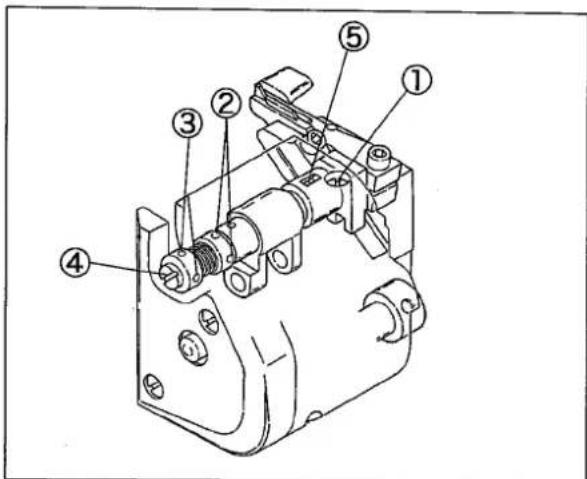
Fig.31
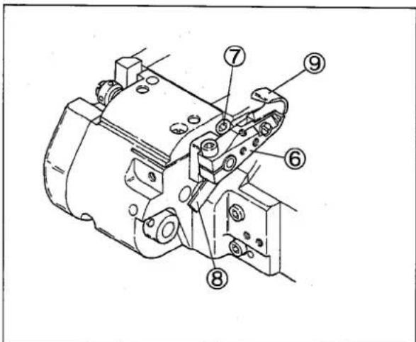
Fig. 32
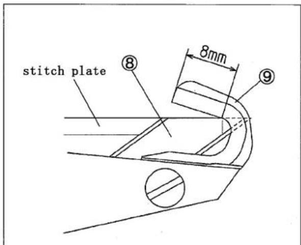
Fig. 33
5.3 Removing and installing the upper knife
How to remove the upper knife
- Loosen the screw ② on upper knife holder and remove the upper knife holder ①.
- Loosen the screw ③ on upper knife and remove the upper knife ④.
How to install the upper knife
- Fix the upper knife ④ to the upper knife holder ① with the screw ③.
- Make the right side surface of upper knife ④ and the right side surface of upper knife shaft ⑤ to be on the same plane, then tighten the screw ② temporarily.
- When the upper knife ④ is at the lowest point, move the upper knife holder ① and make the tip of upper knife to positioned at the point 0.5mm above the top surface of lower knife ⑥ the tighten the screw ②.
- Loosening the screw⑦ on the collar(right) makes the upper ④ and lower knives ⑥ to engage each other by the pressure of spring.
- Check the sharpness of knives by setting a thread between upper④ and lower knives⑥ and turning pulley manually.
- Tighten the screw⑦ on collar(right).
- Check again the sharpness of knives.
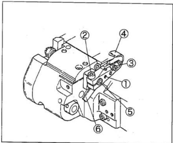
Fig. 34
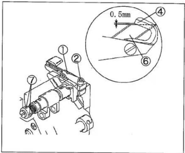
Fig. 35
5.4 Sharpening of lower knife
The upper knife is made of super hard alloy, so it isn't necessary to re-sharpen the knife for about one year. If the sharpness of knives get blunt during this period, re-sharpen the lower knife.
To re-sharpen, see the left fig.
And also prepare the cold water and re-sharpen the lower knife with keeping it cool.
For re-sharpening the upper knife normal grinder is not useful, so it is recommended to keep the upper knife as a spare part, and contact us directly or the dealer for re-sharpening it.
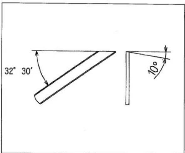
Fig. 36
5.5 Upper knife stroke
At shipping, the stroke of upper knife is adjusted at 5.0mm. To change the stroke of upper knife, follow the sequence as below;
- Remove the bracket side cover①.
- Loosen the screw③ on the stopper②.
- Move the stopper ② to the arrow X direction, the stroke gets bigger and to the arrow Y direction makes it smaller. (Adjust again the engagement of upper knife and lower knife.)
- Tighten the screw③.
natural_image
Technical line drawing of a mechanical device with no visible text or symbolsFig. 37
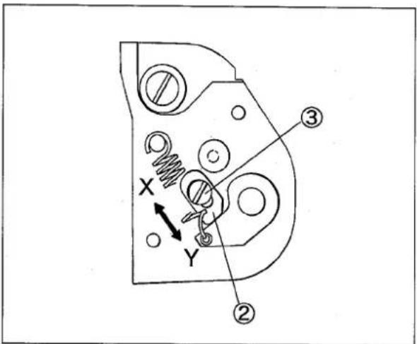
Fig. 38
5.6 How to remove the lower knife holder bracket
- Remove the stitch plate.
- Remove three screws② on lower knife holder bracket①.
- Rotate the hand wheel manually and lower the needle bar to the lowest point.
- Pull out the knock pin③ on lower knife holder bracket① from the frame.
- Pull out the upper knife link(short)⑤ from the upper knife driving lever ④ with tilting the top of lower knife holder bracket① to the front slightly.
NOTE
Move the lower knife holder bracket① to the left side near the frame.
It prevents the adjusting lever block⑥ from pulling out the adjusting lever block guide⑦. If it is pulled out, insert the adjusting lever block⑥ into the adjusting lever block guide⑦ with facing the curved surface of adjusting lever block⑥ to the machine.
- Remove the upper knife driving lever ④ from feed lift shaft ⑧. At the same time, the oil wick ⑨ connected to the upper knife driving lever ④ should be removed.
- Install the frame cover⑩ and the gasket⑪ to the frame by screws⑫.
- Install the supplementary block⑬ to the stitch plate holder⑭.
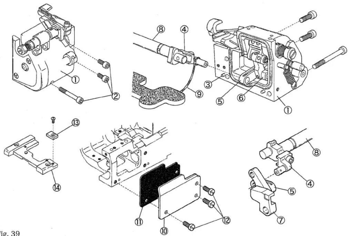
Fig. 39
5.7 How to install the lower knife holder bracket
- Remove the stitch plate.
- Remove the supplementary block① from the stitch plate holder②.
- Remove the frame cover ③ and gasket ④.
- Install the upper knife driving lever⑤ into the feed lift shaft⑥.
Insert the oil wick⑧ connected to the upper knife driving lever⑤ under the felt⑦.
NOTE
Pay attention to the oil wick⑧ not be stretched when the upper knife driving lever⑤ is at the position toward you fully.
- Place the upper knife driving lever⑤ at the position toward you fully.
- Connect the upper knife link(short)⑨ to the upper knife driving lever⑤. On this connecting, stick out the lever block⑩ of the adjusting lever block guide⑪ slightly and pay attention to the block⑩ not come off from the guide⑪.
- Place the bracket gasket⑫ on the groove of lower knife holder bracket⑬ and install the lower knife holder bracket ⑬ with screws ⑭.
- Adjust the position of the lower knife, check the engagement with the upper knife and adjust the pressure of upper knife spring.
| Model | VG2735-31-8F-R |
| Description | Interlock stitch machine with right hand knife trimming mechanism for attaching pre-closed elastic band |
| Dimensions | 445 mm (L) ×220 mm (W) ×405 mm (H) |
| Circumference of Cylinder | 370 mm |
| Weight | 45 kg |
| Stitch Type | ISO 406, 407, 602, 605 |
| Application | Attaching pre-closed elastic band on knitted fabric (avilable width of elastic tape to be sewn : max. 35mm) |
| Sewing Speed | Up to 5500 rpm (with puller : 5000rpm) |
| Stitch Length | 1.4 - 3.6 mmNumber of stitches 7 - 18 stitches per inch(25.4 mm)8 - 21 stitches per 30 mm |
| Needle System | UY×128GAS #9 - #14 (standard: #10) |
| Needle Distance | 3-needle: 4.8 mm, 5.6 mm, 6.4 mm(2-neelde: 3.2 mm, 4.0 mm) |
| Needle Stroke | 33mm |
| Presser Foot Lift | with spreader: 5.5 mm without spreader: 7.5 mm (For 5.6 mm of needle distance ) |
| Feed Regulation | By adjusting screw (available for micro adjustment) |
| Differential Ratio | Standard: 1 : 0.9 - 1 : 1.41 : 0.9 - 1 : 1.8 (stitch length is 2.5 mm or less in max. normal differential)1 : 0.6 - 1 : 1.1 (adjustable by changing position of feed bar connection) |
| Differential Feed Regulation | Micro adjustment by adjusterAdjustable by moving external lever even during operation |
| Lubrication | Lubrication automatically by trochoid-shaped pump |
| Lubricating Oil | YAMATO SF OIL No.28 |
| Capacity of Oil Reservoir | 800 cc |
| Installation | Table top type |
ILLUSTRATED SPARE PARTS LIST
VG2735-31-8F-R VG2735PR-31-8F-R
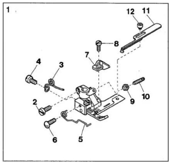
1
VG2735(PR)-31-8F-R(1)
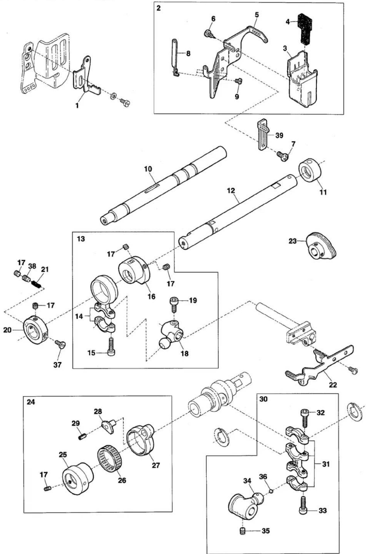
| Ref.No | Parts No. | Description | 品名 | Amt. Req |
| 1 | 3500466 | Needle Thread Guide | 針糸受ケ | 1 |
| 2 | 3500450 | SP Device, Complete Set | SP装置(組) | 1 |
| 3 | 3100384 | SP Container | SPタンク | 1 |
| 4 | 3100386 | Felt | SPフェルト | 1 |
| 5 | 3500281 | Needle Thread Eyelet Bracket | 針糸道台 | 1 |
| 6 | 350009 | Tapping Screw(3×6mm) | タッピンネジ | 2 |
| 7 | 009992 | Screw(M4-0.7×10) | 止ネジ | 2 |
| 8 | 3500451 | Needle Thread Eyelet | 針糸道 | 3 |
| 9 | 110054 | Screw(M3-0.5×3.5) | 止ネジ | 3 |
| 10 | 3500456 | Lower Shaft(Left) | 下軸(左) | 1 |
| 11 | 3500448 | Oil Sleeve | オイルスリーブ | 1 |
| 12 | 3500441 | Upper Shaft(Left) | 上軸(左) | 1 |
| 13 | 3500444 | Connecting Rod, C. Set | 針糸繰リロッド(組) | 1 |
| 14 | 3500446 | Connecting Rod | 針糸繰リロッド | 1 |
| 15 | 120001 | Screw(M4-0.7×14) | 止ネジ | 2 |
| 16 | 3500445 | Needle Thread Take-up Eccentric | 針糸繰リエキセン | 1 |
| 17 | 160003 | Screw(M5-0.8×5) | 止ネジ | 5 |
| 18 | 3500066 | Driving Lever | 針糸繰リ軸腕 | 1 |
| 19 | 120013 | Screw(M6-1×15) | 止ネジ | 1 |
| 20 | 3500442 | Collar | カラー | 1 |
| 21 | 310132 | Oil Wick(Φ4.2×16mm) | 油芯 | 1 |
| 22 | 3500465 | Needle Thread Take-up | 針糸繰リ糸道 | 1 |
| 23 | 3120072 | Looper Thread Take-up | ルーバ糸調子カム | 1 |
| 24 | 3500458 | Looper Rocker Connecting Rod, C. Set | ルーバ前後ロッド(組) | 1 |
| 25 | 3500459 | Looper Rocker Regulating Eccentric | ルーバ前後エキセン | 1 |
| 26 | 0065389 | Roller Bearing | ニードルベアリング | 1 |
| 27 | 3100149 | Looper Rocker Connecting Rod | ルーバ前後ロッド | 1 |
| 28 | 3100151 | Looper Rocker Adjusting Pin | ルーバ前後調節ピン | 1 |
| 29 | 340001 | Spring Pin(Φ1.5×4mm) | スプリングピン | 1 |
| 30 | 3500461 | Looper Connecting Rod, C. Set | ルーバロッド(組) | 1 |
| 31 | 3500460 | Looper Connecting Rod | ルーバロッド | 1 |
| 32 | 110043 | Screw(M4-0.7×14) | 止ネジ | 2 |
| 33 | 120049 | Screw(M4-0.7×16) | 止ネジ | 2 |
| 34 | 3100142 | Looper Driving Lever | ルーバ軸腕 | 1 |
| 35 | 160024 | Screw(M6-1×8) | 止ネジ | 2 |
| 36 | 000637 | Seal Plug | 詰栓 | 1 |
| 37 | 110135 | Screw(M5-0.8×7) | 止ネジ | 1 |
| 38 | 160041 | Screw(M5-0.8×8) | 止ネジ | 1 |
| 39 | 3500467 | Needle Thread Eyelet | 針糸道 | 1 |
2
VG2735(PR)-31-8F-R(2)
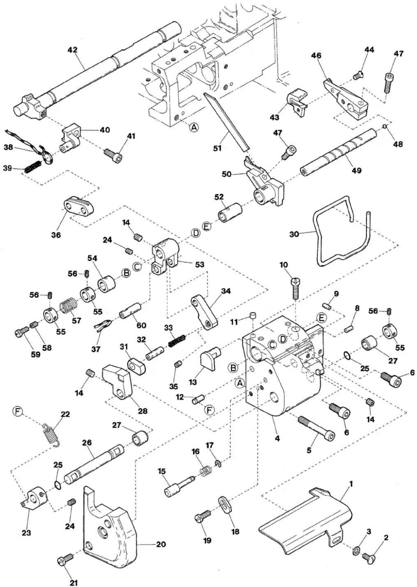
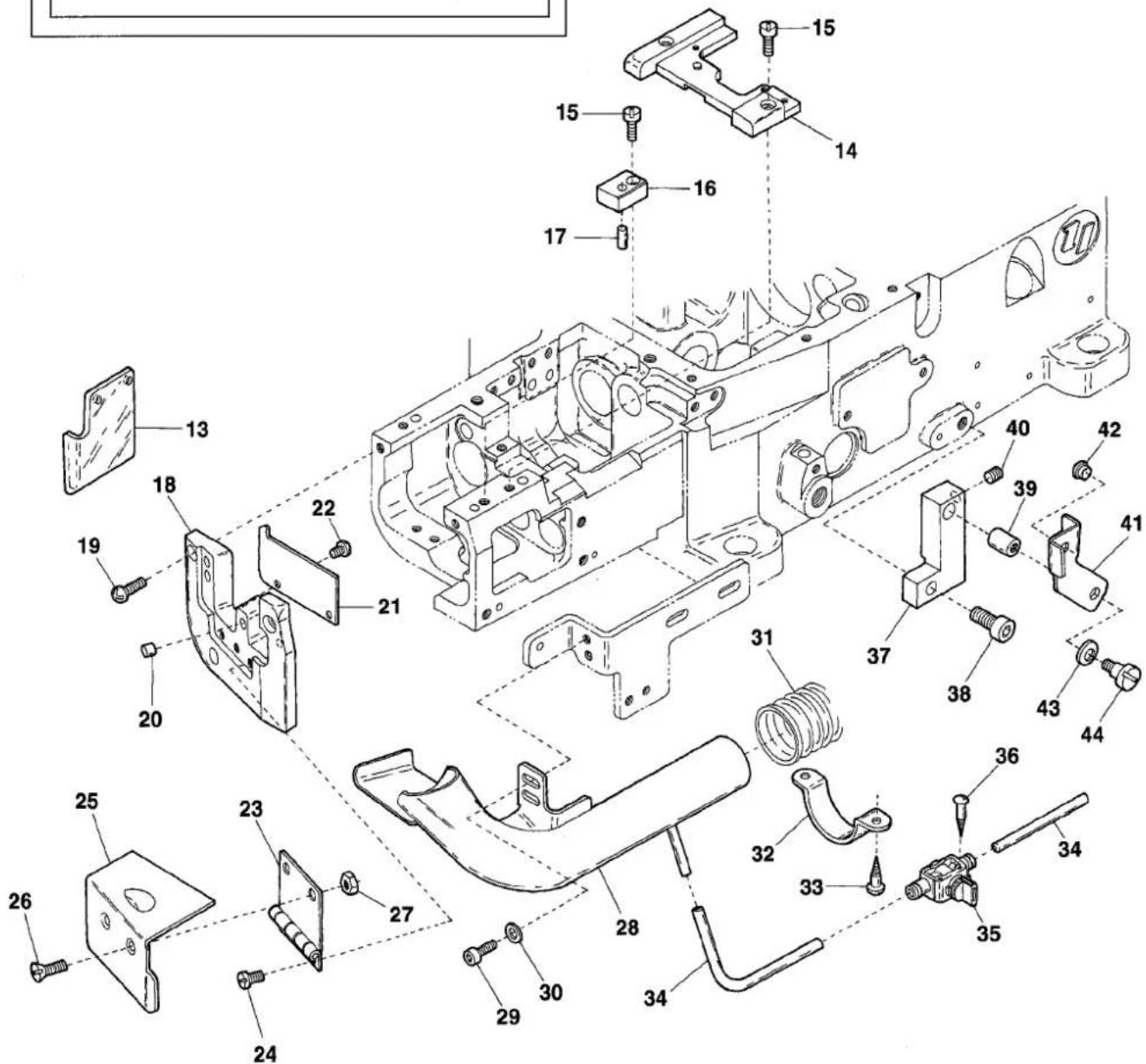
| Ref.No | Parts No. | Description | 品名 | Amt. Req |
| 1 | 3501011 | Fabric Guide | 布ガイド | 1 |
| 2 | 110106 | Screw(M4-0.7 × 8) | 止ネジ | 1 |
| 3 | 000538 | Washer | ワッシャ | 1 |
| 4 | 3501003 | Lower Knife Holder Bracket | 下メス台ブラケット | 1 |
| 5 | 009890 | Screw(M5-0.8 × 35) | 止ネジ | 1 |
| 6 | 120030 | Screw(M5-0.8 × 12) | 止ネジ | 2 |
| 7 | ||||
| 8 | 340043 | Knock Pin(φ 4 × 12mm) | ノックピン | 1 |
| 9 | 340004 | Knock Pin(φ 3 × 8mm) | ノックピン | 2 |
| 10 | 110010 | Screw(M4-0.7 × 16) | 止ネジ | 1 |
| 11 | 000629 | Seal Plug | 詰栓 | 1 |
| 12 | 340003 | Pin(φ 5 × 20mm) | ピン | 1 |
| 13 | 3501022 | Link Guide | リンクガイド | 1 |
| 14 | 160003 | Screw(M5-0.8 × 5) | 止ネジ | 4 |
| 15 | 3101058 | Pushbutton | ブッシュボタン | 1 |
| 16 | 3101059 | Pushbutton Spring | ブッシュボタンパネ | 1 |
| 17 | 0095642 | Retaining Ring | ストップリング | 1 |
| 18 | 3501010 | Stopper | ストッパ | 1 |
| 19 | 110049 | Screw(M4-0.7 × 10) | 止ネジ | 1 |
| 20 | 3501012 | Side Cover | 横カバー | 1 |
| 21 | 110014 | Screw(M4-0.7 × 18) | 止ネジ | 2 |
| 22 | 3501014 | Spring | パネ | 1 |
| 23 | 3501013 | Spring Hanger | パネ掛ケ | 1 |
| 24 | 160001 | Screw(M4-0.7 × 4) | 止ネジ | 1 |
| 25 | 0020551 | O-ring(P5) | Oリング | 2 |
| 26 | 3501015 | Drop Lever Shaft | ドロップレバー軸 | 1 |
| 27 | 3501024 | Lever Shaft Bushing | レバー軸ブッシュ | 2 |
| 28 | 3501018 | Adjusting Lever Block Guide | 角駒ガイド | 1 |
| 29 | ||||
| 30 | 3501029 | Bracket Gasket | 下メス台ブラケットパッキン | 1 |
| 31 | 3501033 | Adjusting Lever Block | 角駒 | 1 |
| 32 | 0032799 | Connection Pin | コネクションピン | 1 |
| 33 | 000278 | Oil Wick(Felt) | 油芯 | 1 |
| 34 | 3501020 | Upper Knife Link(Long) | 上メスリンク(長) | 1 |
| 35 | 160002 | Screw(M4-0.7 × 5) | 止ネジ | 1 |
| 36 | 3501021 | Upper Knife Link(Short) | 上メスリンク(短) | 1 |
| 37 | 310103 | Oil Wick(No.4-50mm) | 油芯 | 1 |
| 38 | 310108 | Oil Wick(No.4-160mm) | 油芯 | 1 |
| 39 | 000309 | Oil Wick(Felt) | 油芯 | 1 |
| 40 | 3501034 | Upper Knife Driving Lever | 上メス駆動腕 | 1 |
Ref. No. 41 to 60 See the following page.
2
VG2735(PR)-31-8F-R(2)
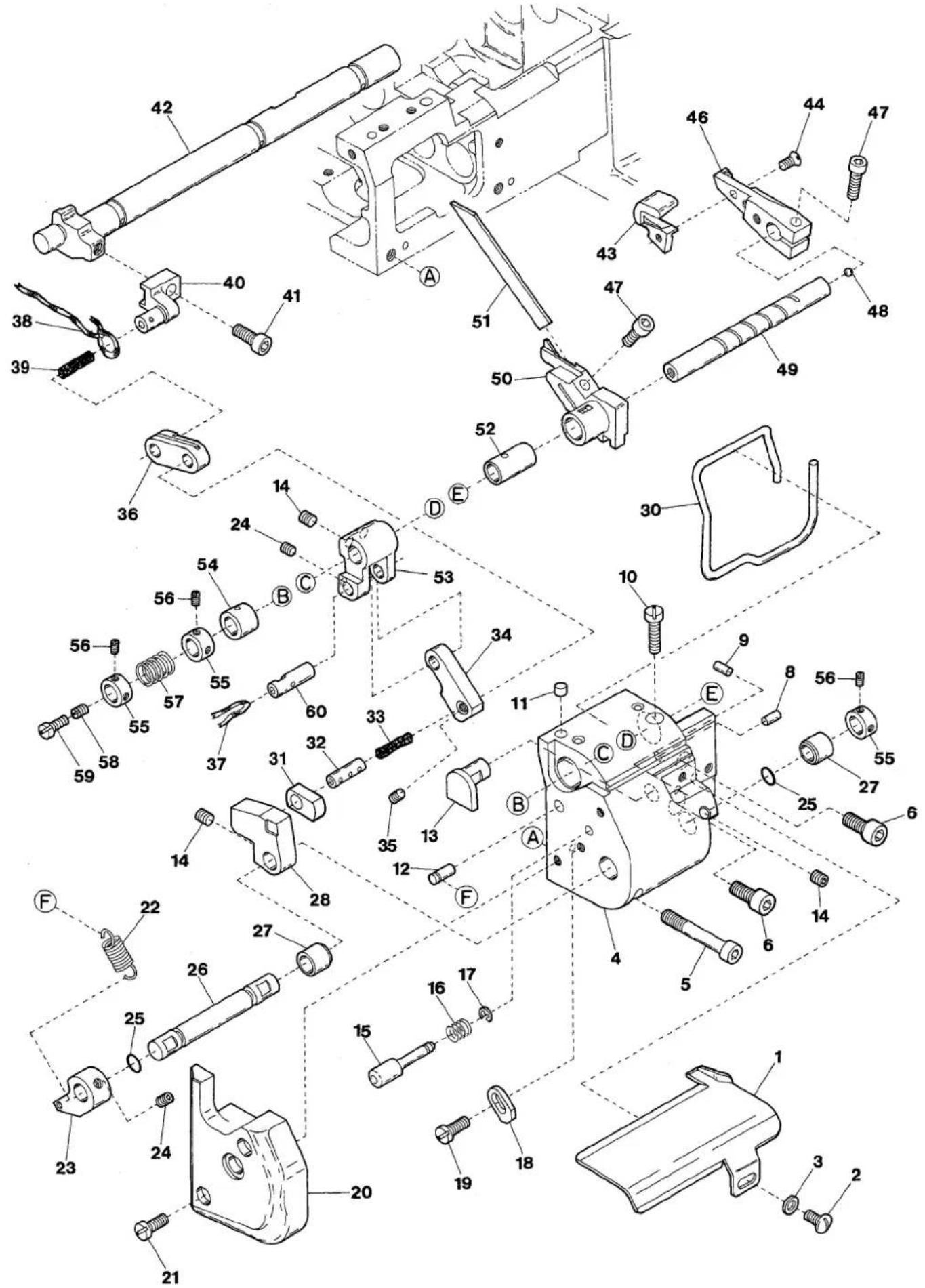
| Ref.No | Parts No. | Description | 品名 | Amt. Req |
| 41 | 120015 | Screw(M5-0.8 × 10) | 止ネジ | 1 |
| 42 | 3501025 | Feed Lift Shaft | 送り上下軸 | 1 |
| 43 | 3501032 | Upper Knife | 上メス | 1 |
| 44 | 130002 | Screw(M3-0.5 × 6) | 止ネジ | 1 |
| 45 | ||||
| 46 | 3501203 | Upper Knife Holder | 上メス台 | 1 |
| 47 | 120001 | Screw(M4-0.7 × 14) | 止ネジ | 2 |
| 48 | 000638 | Seal Plug | 詰栓 | 1 |
| 49 | 3501028 | Upper Knife Shaft | 上メス軸 | 1 |
| 50 | 3501201 | Lower Knife Holder | 下メス台 | 1 |
| 51 | 3501200 | Lower Knife | 下メス | 1 |
| 52 | 3101042 | Lower Knife Holder Bushing | 下メス台ブッシュ | 1 |
| 53 | 3501019 | Upper Knife Driving Lever | 上メスレバー | 1 |
| 54 | 3101022 | Upper Knife Shaft Bushing | 上メス軸ブッシュ | 1 |
| 55 | 3200086 | Collar(8 × 13 × 6mm) | カラー | 3 |
| 56 | 160000 | Screw(M3-0.5 × 3) | 止ネジ | 6 |
| 57 | 0094577 | Upper Knife Spring | 上メスパネ | 1 |
| 58 | 003657 | Screw(M4-0.7 × 3) | 詰ネジ | 1 |
| 59 | 110055 | Screw(M4-0.7 × 14) | 止ネジ | 1 |
| 60 | 3101609 | Upper Knife Driving Lever Pin | 上メスレバーピン | 1 |
3
VG2735(PR)-31-8F-R(3)
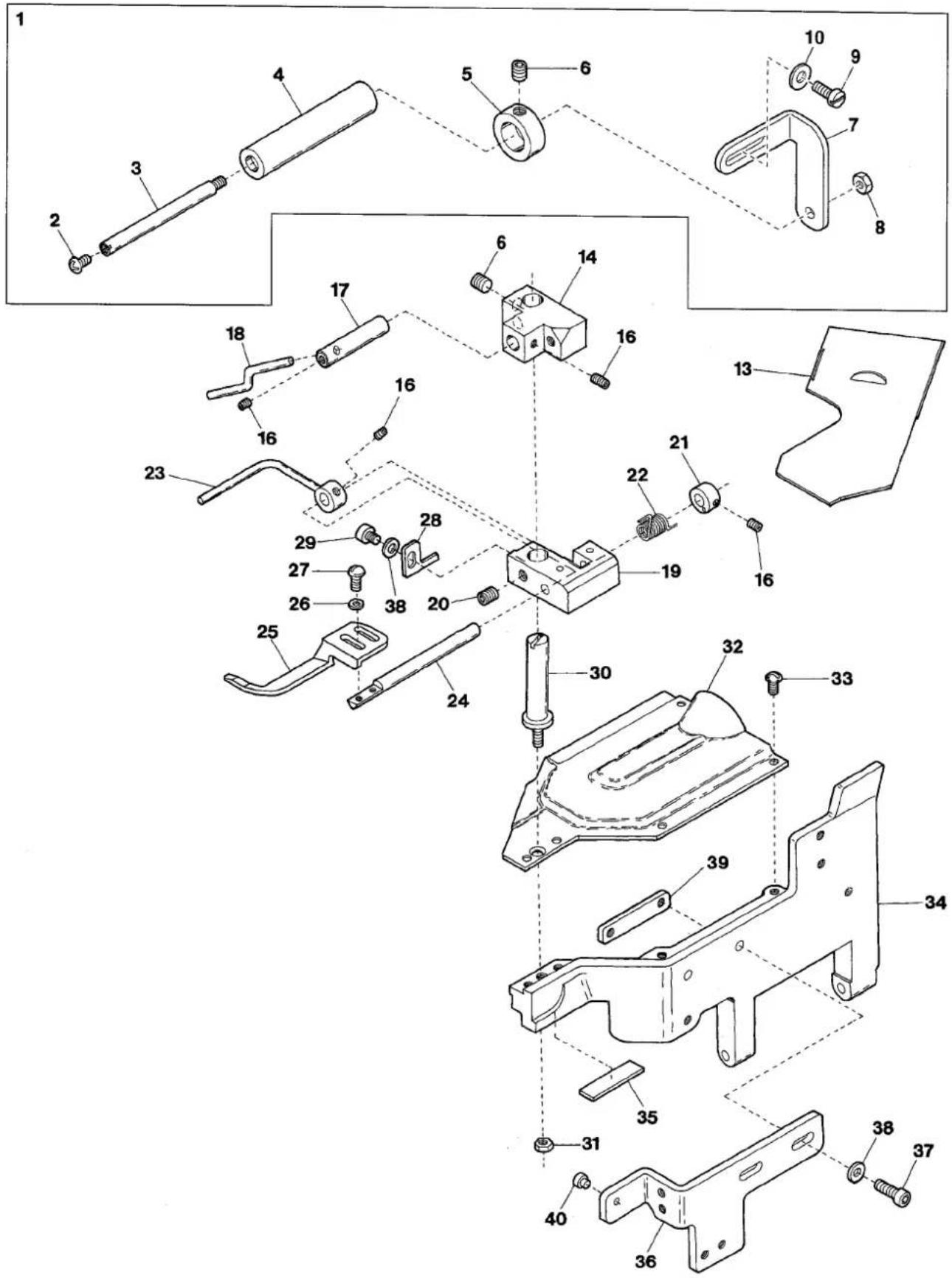
| Ref.No | Parts No. | Description | 品名 | Amt. Req |
| 1 | 3501144 | Lower Roller, Complete Set | 下ローラ(組) | 1 |
| 2 | 110013 | Screw(M4-0.7 × 8) | 止ネジ | 1 |
| 3 | 3501103 | Lower Roller Shaft | 下ローラ軸 | 1 |
| 4 | 3501104 | Lower Roller | 下ローラ | 1 |
| 5 | 3501105 | Lower Roller Guide | 下ローラガイド | 1 |
| 6 | 160004 | Screw(M6-1 × 4.8) | 止ネジ | 3 |
| 7 | 3501145 | Lower Roller Holder | 下ローラ取付板 | 1 |
| 8 | 100001 | Nut | ナット | 1 |
| 9 | 110035 | Screw(M4-0.7 × 10) | 止ネジ | 2 |
| 10 | 000665 | Washer | ワッシャ | 2 |
| 11 | ||||
| 12 | ||||
| 13 | 3501204 | Slide Cover | 滑り板 | 1 |
| 14 | 3501101 | Lower Roller Bracket | 下ローラ台 | 1 |
| 15 | ||||
| 16 | 160001 | Screw(M4-0.7 × 4) | 止ネジ | 4 |
| 17 | 3501058 | Elastic Tape Guide Shaft | ゴムガイド取付軸 | 1 |
| 18 | 3501146 | Elastic Tape Guide | ゴムガイド | 1 |
| 19 | 3501054 | Fabric Presser Shaft Bracket | 布押工軸プラケット | 1 |
| 20 | 160007 | Screw(M6-1 × 6) | 止ネジ | 1 |
| 21 | 3101071 | Collar(6 × 12 × 6mm) | カラー | 1 |
| 22 | 3101070 | Fabric Presser Spring | 布押エパネ | 1 |
| 23 | 3501141 | Fabric Presser Guide Bar | ガイド棒 | 1 |
| 24 | 3101066 | Fabric Presser Shaft | 布押工軸 | 1 |
| 25 | 3501142 | Fabric Presser | 布押工 | 1 |
| 26 | 000535 | Washer | ワッシャ | 2 |
| 27 | 110100 | Screw(M3-0.5 × 6) | 止ネジ | 2 |
| 28 | 3501057 | Guide Bar Stopper | ガイド棒ストッパ | 1 |
| 29 | 006202 | Screw(M4-0.7 × 6) | 止ネジ | 1 |
| 30 | 3101065 | Bracket Holder | ブラケット支工 | 1 |
| 31 | 000206 | Lock Nut(M5-0.8) | ロックナット | 1 |
| 32 | 3501060 | Front Cover(Upper) | 前開キカバー(上) | 1 |
| 33 | 110013 | Screw(M4-0.7 × 8) | 止ネジ | 3 |
| 34 | 3501061 | Front Cover(Lower) | 前開キカバー(下) | 1 |
| 35 | 3501066 | Rubber Cushion | 防振ゴム | 1 |
| 36 | 3501075 | Suction Pipe Holder | 吸込管支工 | 1 |
| 37 | 120001 | Screw(M4-0.7 × 14) | 止ネジ | 2 |
| 38 | 000538 | Washer | ワッシャ | 3 |
| 39 | 3501072 | Suction Pipe Holder Fixing Plate | 吸込管支工止メ板 | 1 |
| 40 | 2100014 | Anti-shock Rubber | 緩衝ゴム | 1 |
4
VG2735(PR)-31-8F-R(4)
VG2735-31-8F-R
VG2735PR-31-8F-R
| Ref.No | Parts No. | Description | 品名 | Amt. Req |
| 1 | 3501120 | Supplementary Roller, C. Set | 補助ローラ(組) | 1 |
| 2 | 3501121 | Supplementary Roller Support | 補助ローラ取付板 | 1 |
| 3 | 000425 | Washer | ワッシャ | 2 |
| 4 | 009954 | Screw(M6-1 × 8) | 止ネジ | 2 |
| 5 | 3501122 | Supplementary Roller | 補助ローラ | 2 |
| 6 | 0065436 | Supplementary Roller Stay(A) | 補助ローラ支工(A) | 2 |
| 7 | 0065437 | Supplementary Roller Stay(B) | 補助ローラ支工(B) | 2 |
| 8 | 110030 | Screw(M3-0.5 × 2.6) | 止ネジ | 8 |
| 9 | 3500698 | Supplementary Roller, C. Set | 補助ローラ(組) | 1 |
| 10 | 3501253 | Supplementary Roller Support | 補助ローラ取付板 | 1 |
| 11 | 000538 | Washer | ワッシャ | 2 |
| 12 | 110009 | Screw(M4-0.7 × 8) | 止ネジ | 2 |
| 13 | 3501080 | Eye Guard | アイガード | 1 |
| 14 | 3501053 | Stitch Plate Holder | 針板台 | 1 |
| 15 | 110041 | Screw(M4-0.7 × 8) | 止ネジ | 3 |
| 16 | 3501052 | Stitch Plate Holder Spacer | 針板台スペーサ | 1 |
| 17 | 000651 | Knock Pin(φ 4 × 10mm) | ノックピン | 1 |
| 18 | 3501051 | Side Cover(Lower) | 横開キカバー(下) | 1 |
| 19 | 110048 | Screw(M4-0.7 × 10) | 止ネジ | 3 |
| 20 | 0092305 | Magnet | マグネット | 1 |
| 21 | 3501049 | Oil Defender | 防油板 | 1 |
| 22 | 006233 | Screw(M3-0.5 × 5) | 止ネジ | 2 |
| 23 | 0068014 | Side Cover Hinge | 横開キカバーヒンジ | 1 |
| 24 | 110003 | Screw(M3.5-0.6 × 6) | 止ネジ | 3 |
| 25 | 3501050 | Side Cover(Upper) | 横開キカバー(上) | 1 |
| 26 | 130007 | Screw(M4-0.7 × 10) | 止ネジ | 2 |
| 27 | 100001 | Nut | ナット | 2 |
| 28 | 3501068 | Suction Pipe | 吸込管 | 1 |
| 29 | 120008 | Screw(M4-0.7 × 8) | 止ネジ | 2 |
| 30 | 001123 | Washer | ワッシャ | 2 |
| 31 | 0012480 | Dust Hose(1500mm) | 集塵ホース | 1 |
| 32 | 0013648 | Hose Band | ホースバンド | 2 |
| 33 | 006921 | Wood Screw(φ 4.8 × 25) | 木ネジ | 4 |
| 34 | 1096030 | Air Tube(6 × 4mm)(Black) | エアチューブ(黒) | - |
| 35 | 1098012 | Hand Valve | ハンドバルブ | 1 |
| 36 | 350006 | Wood Screw(φ 3.5 × 32) | 木ネジ | 2 |
| 37 | 3501062 | Cover Fixing Holder | カバー固定台 | 1 |
| 38 | 120013 | Screw(M6-1 × 15) | 止ネジ | 1 |
| 39 | 3501064 | Cover Fixing Shaft | カバー固定軸 | 1 |
| 40 | 160007 | Screw(M6-1 × 6) | 止ネジ | 1 |
| 41 | 3501063 | Cover Fixing Plate | カバー固定板 | 1 |
| 42 | 330011 | Seal Plug | 詰栓 | 1 |
| 43 | 000010 | Conical Spring Washer | 皿パネワッシャ | 1 |
| 44 | 006004 | Screw(11/64-40 × 9.7) | 止ネジ | 1 |
| 45 | 3501122 | Supplementary Roller | 補助ローラ | 1 |
| 46 | 0065436 | Supplementary Roller Stay(A) | 補助ローラ支工(A) | 1 |
| 47 | 0065437 | Supplementary Roller Stay(B) | 補助ローラ支工(B) | 1 |
| 48 | 110030 | Screw(M3-0.5 × 2.6) | 止ネジ | 4 |
5
VG2735(PR)-31-8F-R(5)
1
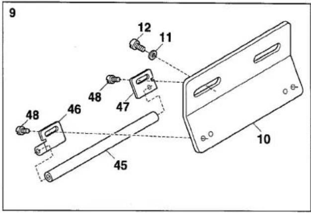
| Ref.No | Parts No. | Description | 品名 | Amt. Req |
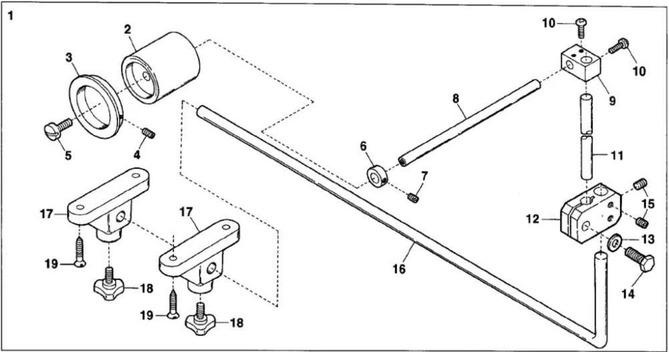
| 1 | 3501125 | Rear Roller, Complete Set | 後ローラ(組) | 1 |
| 2 | 3501126 | Tension Roller, C. Set(1) | テンションローラ(組1) | 1 |
| 3 | 3501127 | Tension Roller | テンションローラ | 1 |
| 4 | 3100770 | Tension Roller Ball Bearing | ボールベアリング | 2 |
| 5 | 009220 | Screw(11/64-40 × 8) | 止ネジ | 1 |
| 6 | 0063469 | Lower Roller Shaft | 下ローラ軸 | 1 |
| 7 | 000016 | Nut | ナット | 3 |
| 8 | 0064173 | Tension Roller Slider | スライダ | 1 |
| 9 | 006475 | Screw(M8-1.25 × 16) | 止ネジ | 1 |
| 10 | 009980 | Guide Screw(M6-1 × 10) | ガイドネジ | 1 |
| 11 | 3501128 | Tension Roller Holder | ホルダ | 1 |
| 12 | 009955 | Screw(M8-1.25 × 65) | 止ネジ | 2 |
| 13 | 000666 | Washer | ワッシャ | 4 |
| 14 | 0031014 | Slider Stop | スライダストップ | 1 |
| 15 | 0031015 | Slider Stop Handle | スライダストップハンドル | 1 |
| 16 | 009853 | Screw(11/64-40 × 6.5) | 止ネジ | 1 |
6
VG2735(PR)-31-8F-R(6)
VG2735 (PR) -156M-31
EXTRA PARTS
| Ref.No | Parts No. | Description | 品名 | Amt. Req |
| 1 | 3507205 | Presser Foot, C. Set(56) | 押工(組) | 1 |
| 2 | 110004 | Screw(M3.5-0.6 × 8) | 止ネジ | 1 |
| 3 | 0091725 | Presser Foot Spring | 押エバネ | 1 |
| 4 | 005133 | Screw(1/8-44 × 4.5) | 止ネジ | 1 |
| 5 | 3107009 | Presser Foot(Small) Spring | 小押エバネ | 1 |
| 6 | 006010 | Screw(1/8-44 × 4.5) | 止ネジ | 1 |
| 7 | 3507209 | Elastic Tape Guide | ゴムガイド | 1 |
| 8 | 004236 | Screw(3/32-56 × 4.2) | 止ネジ | 1 |
| 9 | 000327 | Lock Nut | ロックナット | 1 |
| 10 | 003302 | Adjusting Screw(1/8-44 × 11) | 調節ネジ | 1 |
| 11 | 3507208 | Elastic Tape Guide(large) | ゴムガイド(大) | 1 |
| 12 | 120057 | Screw(M3-0.5 × 2.5) | 止ネジ | 1 |
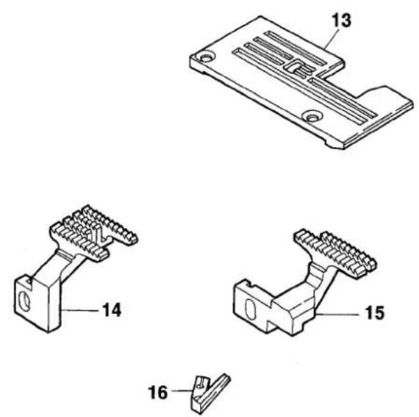
| 13 | 3508214 | Stitch Plate(56M) | 針板 | 1 |
| 14 | 3509068 | Main Feed Dog | 後送り | 1 |
| 15 | 3109024 | Differential Feed Dog | 前送り | 1 |
| 16 | 3509202 | Needle Guard(Rear) | 針受ケ(後) | 1 |
| 17 | ||||
| 18 | ||||
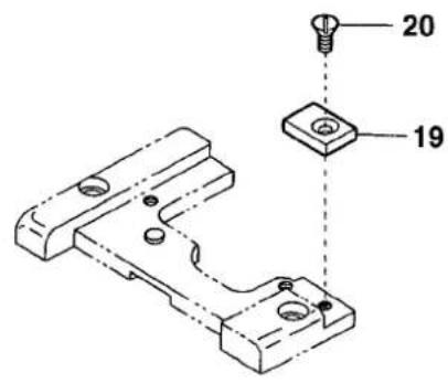
| 19 | 3501132 | Supplementary Block | 補助ブロック | 1 |
| 20 | 130002 | Screw(M3-0.5 × 6) | 止ネジ | 1 |
| 21 | 3501131 | Frame Cover Gasket | ベッドカバーパッキン | 1 |
| 22 | 3501130 | Frame Cover | ベッドカバー | 1 |
| 23 | 110011 | Screw(M5-0.8 × 10) | 止ネジ | 3 |
7
VG2735(PR)-31-8F-R(7)
| Ref.No | Parts No. | Description | 品名 | Amt. Req |
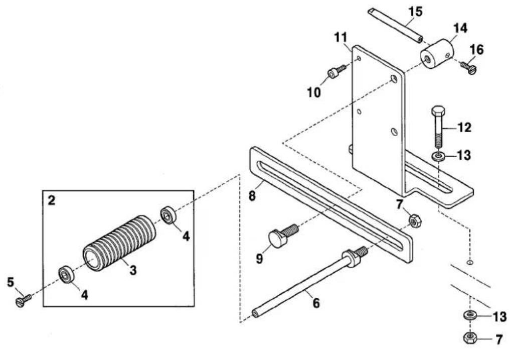
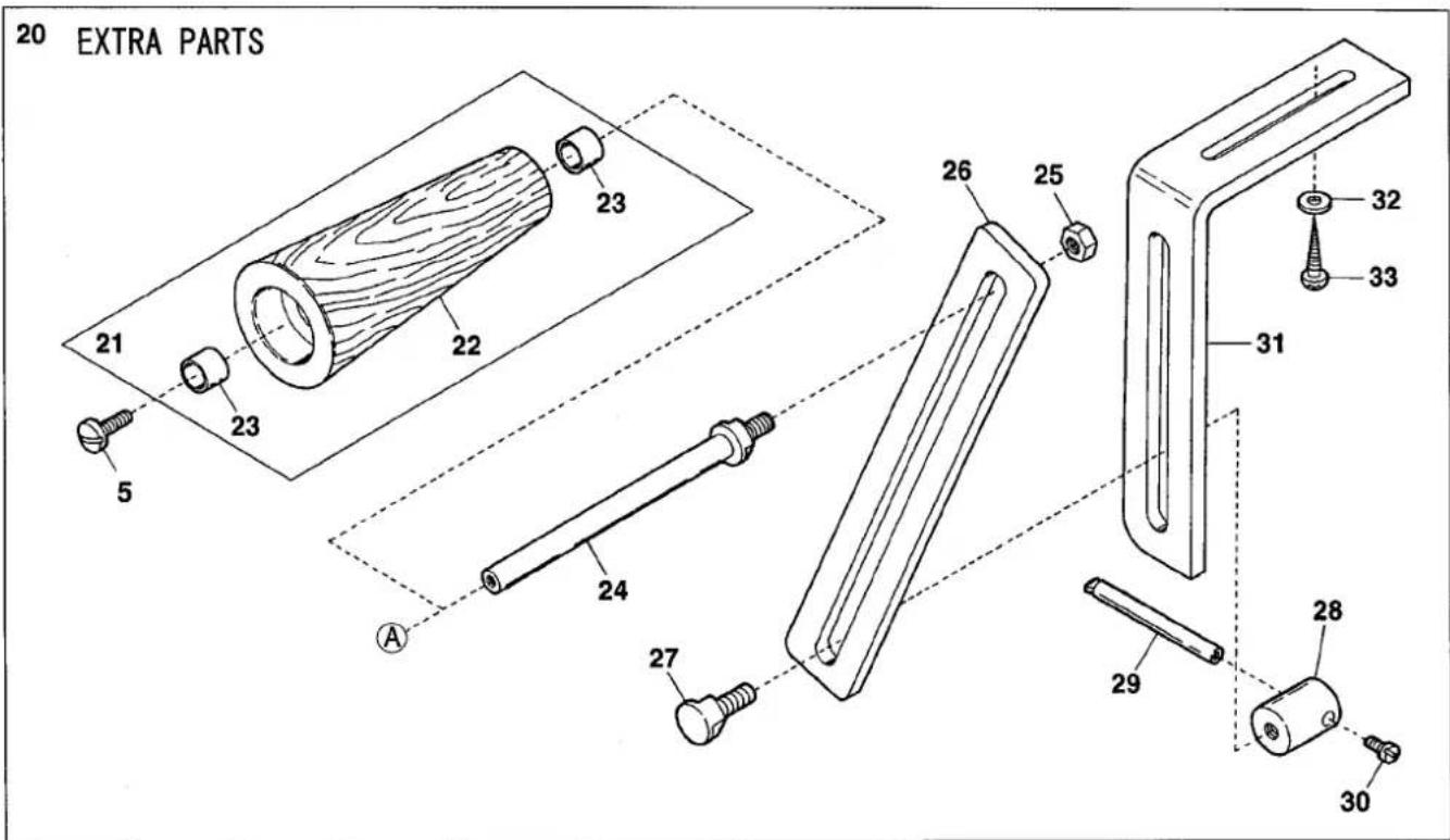
| 1 | 3101087 | Elastic Tape Front Roller, C. Set | 前ローラ(組) | 1 |
| 2 | 0064241 | Elastic Tape Front Roller | 前ローラ | 1 |
| 3 | 0064243 | Front Roller Guide | 前ローラゴムガイド | 1 |
| 4 | 003638 | Screw(11/64-40 × 4) | 止ネジ | 1 |
| 5 | 009220 | Screw(11/64-40 × 8) | 止ネジ | 2 |
| 6 | 0032719 | Collar(10 × 16 × 6mm) | カラー | 1 |
| 7 | 001459 | Screw(9/64-40 × 3) | 止ネジ | 1 |
| 8 | 3101086 | Elastic Tape Front Roller Shaft | 前ローラ軸 | 1 |
| 9 | 0011166 | Front Roller Block | 前ローラブロック | 1 |
| 10 | 009973 | Screw(M5-0.8 × 10) | 止ネジ | 4 |
| 11 | 0064245 | Front Roller Block Shaft | 前ローラブロック取付軸 | 1 |
| 12 | 3120243 | Elastic Tape Front Roller Connector | 前ローラ継手 | 1 |
| 13 | 000429 | Washer | ワッシャ | 1 |
| 14 | 009891 | Screw(M8-1.25 × 20) | 止ネジ | 1 |
| 15 | 160007 | Screw(M6-1 × 6) | 止ネジ | 3 |
| 16 | 3120245 | Elastic Tape Front Roller Holding Shaft | 前ローラ支エ軸 | 1 |
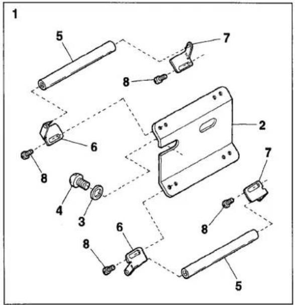
| 17 | 0067025 | Bracket | ブラケット | 2 |
| 18 | 009877 | Knob Bolt(M10-1.5 × 20) | ノブボルト | 2 |
| 19 | 009947 | Wood Screw(φ 5.1 × 25) | 木ネジ | 4 |
| 20 | 0064252 | Elastic Tape Lower Roller, C. Set(2) | 下ローラ(組2) | 1 |
| 21 | 0063471 | Tension Roller, C. Set(1) | テンションローラ(組1) | 1 |
| 22 | 0063470 | Lower Roller | 下ローラ | 1 |
| 23 | 0063460 | Lower Roller Bushing | 下ローラブッシュ | 2 |
| 24 | 0063469 | Lower Roller Shaft | 下ローラ軸 | 1 |
| 25 | 000016 | Nut | ナット | 1 |
| 26 | 0064173 | Tension Roller Slider | スライダ | 1 |
| 27 | 006475 | Screw(M8-1.25 × 16) | 止ネジ | 1 |
| 28 | 0031014 | Tension Roller Slider Stop | スライダストッパ | 1 |
| 29 | 0031015 | Tension Roller Slider Stop Handle | ストッパハンドル | 1 |
| 30 | 009853 | Screw(11/64-40 × 6.5) | 止ネジ | 1 |
| 31 | 0065258 | Lower Roller Support | 下ローラ台 | 1 |
| 32 | 000428 | Washer | ワッシャ | 2 |
| 33 | 006920 | Wood Screw(φ 5.8 × 32) | 木ネジ | 2 |
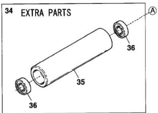
| 34 | 3100768 | Tension Roller, C. Set(1) | テンションローラ(組1) | 1 |
| 35 | 3100769 | Tension Roller | テンションローラ | 1 |
| 36 | 3100770 | Tension Roller Ball Bearing | ボールベアリング | 2 |
1jamato
ヤマトミシン製造株式会社
YAMATO SEWING MACHINE MFG. CO., LTD.
4-4-12, NISHITENMA, KITA-KU, OSAKA, JAPAN
TEL:81-6-6364-1321 FAX:81-6-6364-1307
〒530-0047 大阪市北区西天満4丁目4番12号
TEL(06)6364-1321(代) FAX(06)6365-5176