
IR-S1L - Overvågningskamera BLAUPUNKT - Gratis brugsanvisning og manual
Find enhedens vejledning gratis IR-S1L BLAUPUNKT i PDF-format.

Brugerspørgsmål om IR-S1L BLAUPUNKT
0 spørgsmål om dette apparat. Besvar dem du kender, eller stil dit eget.
Stil et nyt spørgsmål om dette apparat
Download vejledningen til din Overvågningskamera i PDF-format gratis! Find din vejledning IR-S1L - BLAUPUNKT og tag din elektroniske enhed tilbage i hånden. På denne side er alle dokumenter nødvendige for brugen af din enhed offentliggjort. IR-S1L af mærket BLAUPUNKT.
BRUGSANVISNING IR-S1L BLAUPUNKT
Wireless Pet-Immune PIR Motion Sensor (IRP-S1L)
natural_image
Technical line drawing of a rectangular enclosure with internal compartments and mounting holes (no text or symbols)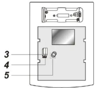
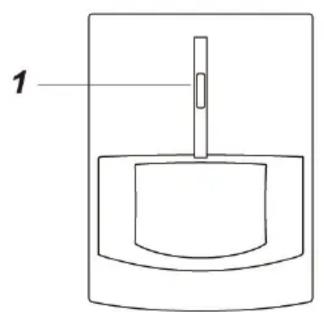
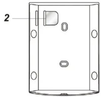
Parts Description
1. Learn/Test Button & LED indicator
Press the button to transmit a learn/test code and enter Test mode for 3 minutes. The LED will light up whenever a movement is detected under Test mode.
2. Battery Insulator
3. Supervision Enable/Disable Jumper Switch (JP2)
4. High/Low Sensitivity Jumper Switch (JP3)
5. Tamper Switch
The Tamper switch protects the PIR from unauthorized cover opening.
Package Content
1 x PIR Sensor
4 x wall plugs and screws
1 x 3V lithium battery(pre-installed)
Supervision Enable/Disable Jumper Switch (JP2)

Jumper On
The jumper link is inserted connecting the two pins

Jumper Off
if the jumper link is removed or parked on one pin.
If enabled, the PIR sensor will transmit supervision signal to Control Panel periodically for the sensor to monitor PIR sensor condition.
Jumper set to ON = supervision function is Disabled
Jumper set to OFF = supervision function is Enabled (Default)
High/Low Sensitivity Jumper Switch (JP3)

Jumper On
The jumper link is inserted connecting the two pins

Jumper Off
if the jumper link is removed or parked on one pin.
Jumper set to ON = PIR sensitivity is set to High (Default)
Jumper set to OFF= PIR sensitivity is set to Low
Learning
Put the Control Panel into learning mode, then press the learn button to transmit learn code. Please refer to Control Panel manual for to complete the learning process.
Installation
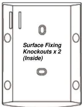
The PIR Sensor has knockouts on the back where plastic is thinner. The 2 center knockouts are for flat wall mounting, and the 4 side knockouts are for corner mounting. Mount the PIR Sensor at 1.9m to 2m height for optimal performance.
- Break through the knockouts; use the knockouts to mark position on the wall or corner.
- Drill holes into the wall or corner using the knockouts as template.
- Fix the PIR Sensor base onto the wall with the screws and plugs provided.
- Replace the PIR Sensor cover onto the base.
Corner Fixing Knockouts x 4
Operation
Sleep Timer
The PIR features a “sleep time” of approximately 1 minute for power conservation. After transmitting a detected movement, the PIR will not retransmit for 1 minute. Any further movement detected during this sleep period will extend the sleep time by another minute. In this way continuous movement in front of a PIR will not unduly exhaust the battery.
Test Mode
Press the Test Button to enter Test mode for 3 minutes. Sleep timer will be disabled under Test mode, and the LED indicator will flash every time a movement is detected. Use the Test mode to determine PIR detection coverage and plan the installation location accordingly.
LED Indicator
| Off | Normal Operation |
| On (2 seconds) | - When Tamper Switch is triggered- Movement detection under low battery, tamper triggered, or Test mode. |
Pet Immunity
The PIR has pet-immune function and will not trigger false alarm from household pet under approximately 27 kg within 7 meters. Please note this is a rough estimate number and the actual pet immune performance may vary according to your home environment and pet size. For example, a dog standing on its hind legs or a cat climbing on furniture may trigger alarm more easily than when they are standing on floor. Please test the pet immune function with your pets to find out the ideal installation location before mounting the PIR.
Battery
The PIR uses one 3V lithium battery as its power source. Remove the battery insulator to activate battery. It also features low battery detection function to notify the Control Panel when battery voltage is low.
When PIR is on low battery, follow the procedure below to change the batteries.
- Open the PIR back cover.
- Remove the old batteries.
- Press the tamper switch several times to fully discharge.
- Insert the new batteries observing correct polarity. The PIR LED will light up for 30 seconds to indicate it is warming up.
- Replace the PIR back cover.
Specification
Environmental Condition
-10 °C to 40 °C, relative humidity 85% non-condensing.
Radio
868 MHz