
Huskylock 700 - Symaskine HUSQVARNA - Gratis brugsanvisning og manual
Find enhedens vejledning gratis Huskylock 700 HUSQVARNA i PDF-format.

Brugerspørgsmål om Huskylock 700 HUSQVARNA
0 spørgsmål om dette apparat. Besvar dem du kender, eller stil dit eget.
Stil et nyt spørgsmål om dette apparat
Download vejledningen til din Symaskine i PDF-format gratis! Find din vejledning Huskylock 700 - HUSQVARNA og tag din elektroniske enhed tilbage i hånden. På denne side er alle dokumenter nødvendige for brugen af din enhed offentliggjort. Huskylock 700 af mærket HUSQVARNA.
BRUGSANVISNING Huskylock 700 HUSQVARNA
"IMPORTANT SAFETY INSTRUCTIONS"
When using the sewing machine, basic safety precautions should always be followed, including the following.
"Read all instructions before using."
DANGER — To reduce the risk of electric shock.
- The sewing machine should never be left unattended when plugged in. Always unplug this sewing machine
from the electrical outlet immediately after using and before cleaning.
- Always unplug before relamping. Replace bulb with same type rated 15 watts.
WARNING — To reduce the risk of burns, fire, electric shock, or injury to persons.
-
Do not allow to be used as a toy. Close attention is necessary when the sewing machine is used by or near children.
-
Use this sewing machine only for its intended use as described in this manual. Use only accessories recommended by the manufacturer as contained in this manual.
-
Never operate this sewing machine if it has a damaged cord or plug, if it is not working properly, it has been dropped or damaged, or dropped into water. Return the sewing machine to the nearest authorized dealer or service center for examination, repair, electrical or mechanical adjustment.
-
Never operate the sewing machine with any air openings blocked. Keep ventilation openings of the sewing machine and foot controller free from the accumulation of lint, dust, and loose cloth.
-
Never drop or insert any object into any openings.
-
Do not use outdoors.
- Do not operate where aerosol (spray) products are being used or where oxygen is being administered.
-
To disconnect, turn the main switch to the symbol "O" position which represents off, then remove plug from outlet.
-
Do not unplug by pulling on cord. To unplug, grasp the plug, not the cord.
-
Do not unplug by pulling on cord. To unplug, group and group.
-
Keep fingers away from all moving parts. Special care is required around the sewing machine needle.
-
Always use the proper needle plate. The wrong plate can cause the needle to break.
-
Do not use bent needles.
- Do not pull or push fabric while stitching. It may deflect the needle causing it to break.
-
Switch the sewing machine to the symbol "O" position when making any adjustments in the needle area, such as threading needle, changing needle, or changing presser foot, and the like.
-
Always unplug the sewing machine from the electrical outlet when removing covers, lubricating, or when making any other user servicing adjustments mentioned in the instruction manual.
"SAVE THESE INSTRUCTIONS" "This sewing machine is intended for household."
- When leaving this sewing machine unattended, the mains switch of the machine must be switched off or the plug must be removed from the socket-outlet.
- When servicing the sewing machine, or when removing covers or changing lamps, the machine or the electrical set must be disconnected from the supply by removing the plug from the socket-outlet.
FOR USERS IN THE UK, EIRE, MALTA AND CYPRUS ONLY.
If your sewing machine is fitted with a 3 pin non rewireable BS plug then please read the following.
IMPORTANT
If the available socket outlet is not suitable for the plug supplied with this equipment, it should be cut off and an appropriate three pin plug fitted. With alternative plugs an approved fuse must be fitted in the plug.
NOTE: The plug severed from the mains lead must be destroyed as a plug with bared flexible cords is hazardous if engaged in a live socket outlet. In the event of replacing the plug fuse, use a fuse approved by ASTA to BS 1362, i.e. carrying the ✉ mark, rating as marked on plug.
Always replace the fuse cover, never use plugs with the fuse cover omitted.
WARNING: DO NOT CONNECT EITHER WIRE TO THE EARTH TERMINAL WHICH IS MARKED WITH THE LETTER 'E', BY THE EARTH SYMBOL 12 OR COLOURED GREEN OR YELLOW.
The wires in this mains lead are coloured in accordance with the following code:
Blue
Brown
Neutral
Live
As the colours of the wiring in the mains lead of this appliance may not correspond with the coloured markings identifying the terminals in your plug, proceed as follows.
The wire which is coloured blue must be connected to the terminal which is marked with the letter 'N' or coloured black or blue.
The wire which is coloured brown must be connected to the terminal which is marked with the letter 'L' or coloured red or brown.
CONGRATULATIONS ON CHOOSING THIS COMPACT OVERLOCK MACHINE
Your machine is a high quality, easy-to-use product. To fully enjoy all the features, we suggest that you study this booklet. If you need more information regarding the use of your machine, your nearest authorized dealer is always happy to be of service. Enjoy yourself!
FELICITACIONES POR HABER ELEGIDO ESTA COMPACTA MAQUINA OVERLOCK
Su máquina es de una eficacia y calidad excelentes; así pues, a fin de disfrutar completamente de todas las características incorporadas, le sugerimo estudie el manual. Si se necesitara mayor información sobre el uso de esta máquina, el proveedor autorizado más cercano estará encantado de ofrecerle sus servicios.
CAUTION!
WHEN THREADING, REPLACING NEEDLE OR LIGHT BULB, BE SURE TO TURN OFF THE MAIN POWER SWITCH OF THE MACHINE. WHEN THE MACHINE IS NOT IN USE, IT IS RECOMMENDED THAT THE ELECTRIC SUPPLY PLUG IS DISCONNECTED FROM THE WALL SOCKET TO AVOID ANY POSSIBLE HAZARDS.
¡PRECAUCION!
ASEGURARSE DE QUE EL INTERRUPTOR GENERAL DE LA MAQUINA ESTE APAGADO CUANDO SE ENHEBRE, REEMPLACE LA AGUJA O CAMBIE LA LAMPARITA. CUANDO NO SE UTILICE LA MAQUINA, SE RECOMIENDA QUE EL ENCHUFE ESTE DES- CONECTADO DE LA RED DE LA CORRIENTE, A FIN DE EVITAR CUALQUIER PELIGRO.
Notes on the motor
- The normal operating speed of this sewing machine is 1,500 stitches per minute, which is quite fast compared to the normal operating speed of 300 to 800 stitches per minute for the ordinary foot-operated sewing machine.
- The bearings in the motor are made of a special sintered, oil-impregnated alloy mounted in oil-soaked felt to withstand long hours of continuous operation.
- Continuous operation of the sewing machine can cause heat to build in the motor area, but not enough to adversely affect its performance. It is important to keep fabric and paper away from the ventilating holes on the back and sides of the machine so air can get to these wholes.
- When the motor is running, sparks can be seen through the ventilating hole in the motor bracket on the side opposite the hand wheel. These sparks are produced by the carbon brushes and the commutator, and are part of the machines normal operation.
CAUTION
WHEN THREADING THE MACHINE, REPLACING A NEEDLE, OR WHEN THE MACHINE IS NOT IN USE, WE RECOMMEND DISCONNECTING THE ELECTRIC SUPPLY PLUG TO AVOID ANY POSSIBLE HAZARDS.
NOTAS SOBRE EL MOTOR
- La velocidad normal de funcionamiento de esta máquina de coser es de 1.500 puntadas por minuto, lo que resulta bastante rápido comparado con la velocidad normal de 300 a 800 puntadas por minuto de las máquinas de coser normales que funcionan con pedal.
- Los cojinetes del motor están hechos de una aleación especial impregnada en aceite sintético y montada en un fieltro impregnado en aceite, para poder funcionar continuamente durante muchas horas.
- Un funcionamiento continuo de la máquina puede contribuir a calentar algo la máquina en la zona del motor, pero no lo suficiente como para alterar su rendimiento y funcionamiento.
Sin embargo, es menester mantener los orificios de ventilación de la parte trasera y en los lados de la máquina sin tapar con tejido o papel durante el uso, para que el aire pueda circular por los orificios. - Durante el funcionamiento del motor, se pueden ver chispas a través del orificio de ventilación de la abrazadera del motor, en el lado contrario a la ruedecilla. Estas chispas son producidas por las escobillas de carbón que entran en contacto con el conmutador, y forman parte del funcionamiento normal de la máquina.
PRECAUCION
Al enhebrar la máquina, cambiar una aguja o al dejar la máquina sin usar, le recomendamos desenchufar la máquina para evitar cualquier peligro de corto circuito.
TABLE OF CONTENTS
Chapter 1 Names of Parts and Their Functions
Accessories included with your serger
Needle .... 3
Turning direction of motor 5
Opening and closing the front cover
Chapter 2 Operating
Powering the machine
Chapter 3 Stitch Length
Stitch Width
Chapter 4 Instructions for the Differential Feed Mechanism....10
Chapter 5 Threading ....
Preparation 14
How to use the thread spool cap 14
How to use the thread net 14
Before threading....15
Threading the upperlooper 16
Threading the lowerlooper 17
Threading the right needle 19
Threading the left needle 21
Chapter 6 Setting for Two-thread Overlock Stitch Sewing 23
Chapter 7 Comparison Chart of Sewing Materials, Threads and Needles 25
Chapter 8 Thread Tension ...... 27
Chapter 9 Chart of Thread Tension Adjustment 29
Chapter 10 Test-sewing
Chaining-off 31
Chapter 11 Sewing
To start sewing 33
To remove work 33
If threads break during sewing 34
To sew heavy materials 34
To sew fine materials 35
Presser foot pressure 35
Chapter 12 Troubleshooting....37
Chapter 13 Stitch selection
Narrow overlock stitch/Rolled edge stitch 39
Chapter 14 Chart of Narrow Overlock/Rolled Edge Stitch ....43
Chapter 15 Examples of Sewing Applications by Using Optional Blind Stitch Foot
Blind stitching with blind stitch presser foot....45
Flatlock stitching with blind stitch presser foot 46
Pintuck stitching with blind stitch presser foot 48
Decorative stitching .... 50 .... 52
Chapter 16 Upper Cutter and Lower Cutter
Retracting upper cutter 53
Replacing the cutters 53
Chapter 17 Oiling ....
Chapter 18 Changing the Light Bulb 56
Chapter 19 Machine Specifications ....
Chapter 20 SETTING RECORD ....58
INDICE
Capítulo 1 Nombres de las partes y sus funciones ....1
Accesorios incluidos con la máquina de coser 3
Aguja 5
Para cambiar la dirección del motor....7
Abre y cierre de la tapa delantera 7
Capítulo 2 Funcionamiento ....8
Encendido de la máquina 8
Capítulo 3 Largo de puntada....9
Ancho de puntada 9
Capítulo 4 Instrucciones para el mecanismo de alimentación con diferencial ....10
Capítulo 5 Enhebrado 14
Preparación 14
Como utilizar el tope del carrete 14
Como utilizar la malla para hilo 15
Antes de enhebrar 16
Enhebrado del áncora superior 17
Enhebrado del áncora inferior 19
Enhebrado de la aguja derecha 21
Enhebrado de la aguja izquierda 22
Capítulo 6 Ajuste para coser con puntada overlock de dos hilos....23
Capítulo 7 Tabla de relación entre los distintos tejidos, hilos y agujas ......26
Capítulo 8 Tensión del hilo 27
Capítulo 9 Tabla de ajuste de tensión de los hilos 29
Capítulo 10 Costura de prueba ....31
Cadeneta 32
Capítulo 11 Costura ....33
Para empezar a coser 33
Para retirar el trabajo 34
Si el hilo se rompe al coser 34
Para coser tejidos gruesos....35
Para coser tejidos finos 35
Presión del prensatelas 36
Capítulo 12 Guía de localización de fallas....38
Capítulo 13 Selección de las distintas puntadas....39
Puntada overlock estrecha/puntada de borde enrollado....40
Capítulo 14 Tabla para puntadas overlock estrechas/de borde enrollado ....44
Capítulo 15 Ejemplos de aplicaciones de costuras con el
prensatelas para puntadas invisibles (optativo) 45
Puntadas invisibles con prensatelas multipropósito 46
Costura Overlock plana con prensatelas multipropósito 48
Costuras de pliegues pequeños con prensatelas multipropósito 50
Puntadas decorativas 52
Capítulo 16 Cuchillas superior e inferior ....53
Para esconder la cuchilla superior 53
Cambio de las cuchillas 53
Capítulo 17 Engrasado....55
Capítulo 18 Cambio de la bombilla de luz 56
Capítulo 19 Especificaciones técnicas de la máquina....57
Capítulo 20 NOTAS DE AJUSTES ....59
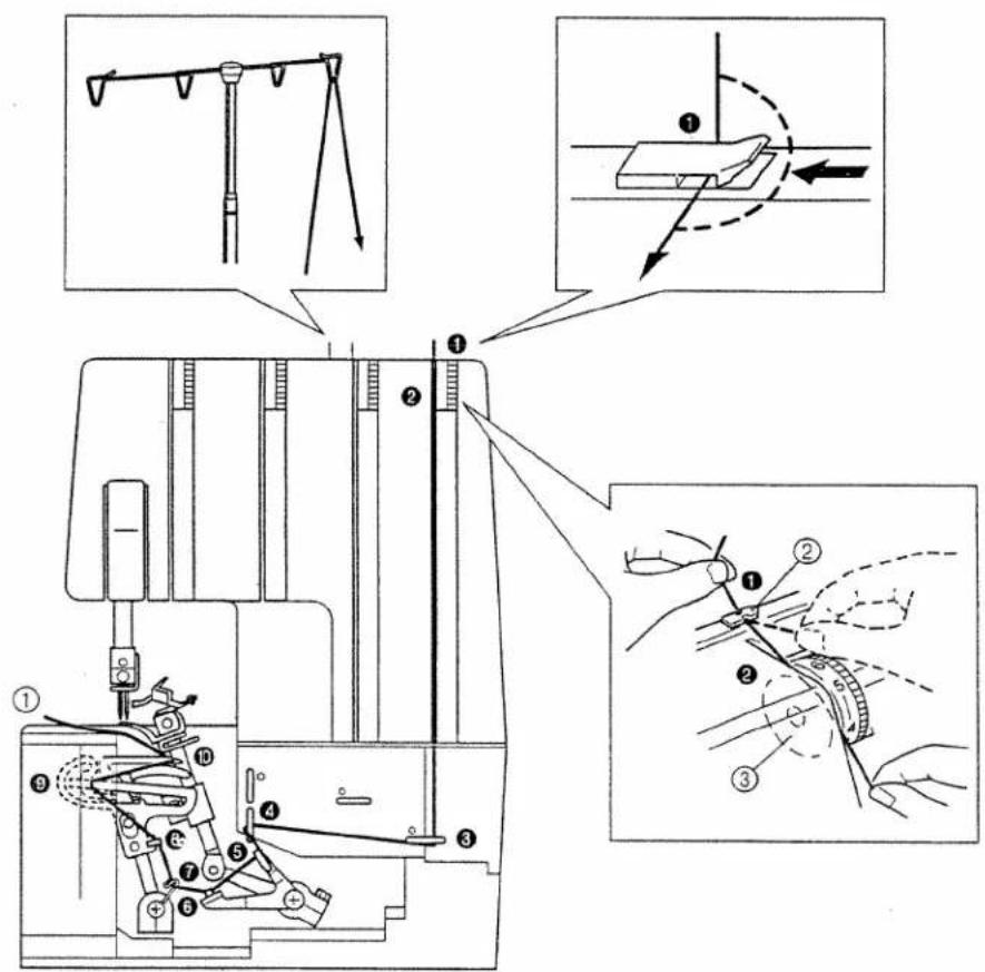
1
Names of Parts and Their Functions
Nombres de las partes y sus funciones
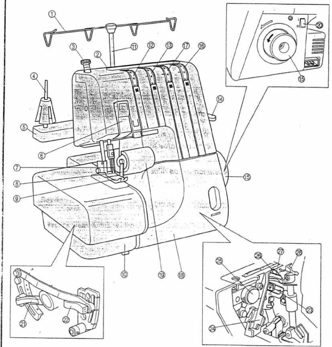
Thread guide
② Handle
3 Pressure adjustment screw
④ Spool pin
⑤ Spool support
⑥ Thread take-up
⑦ Needles
8 Upper cutter
9 Presser foot
10 Material plate cover
⑪ Thread pole
12 Left needle thread tension dial
⑬ Right needle thread tension dial
14 Presser foot lifting lever
15 Hand wheel
16 Lowerlooper thread tension dial
⑰ Upperlooper thread tension dial
13 Front cover
19 Cutter guard
20 Main power switch and light switch
② Stitch length adjustment lever
22 Differential feed ratio adjustment lever
23 Lowerlooper threading lever
24 Removal stitch finger for rolled edge
25 Stitch width dial
26 Upperlooper
27 Lowerlooper
28 Two-thread converter lever
① Guia del hilo
② Asa
③ Tornillo de ajuste de la presión
④ Eje del carrete
⑤ Filete del carrete
⑥ Toma de hilo
⑦ Agujas
B Cuchilla superior
9 Prensatelas
⑩ Tapa de tejido
⑪ Barra de hilos
⑫ Disco de tensión del hilo de la aguja izquierda
13 Disco de tensión del hilo de la aguja derecha
14 Palanca de levantamiento del prensatelas
15 Ruedecilla
16 Disco de tensión del hilo del áncora inferior
⑰ Disco de tensión del hilo del áncora superior
18 Tapa delantera
19 Protección de las cuchillas
20 Interruptor de alimentación principal e interruptor de luz
21 Palanca de ajuste del largo de las puntadas
22 Palanca diferencial de ajuste de la velocidad de alimentación
23 Palanca de enhebrado del áncora inferior
24 Uñeta de puntadas amovible para bordes enrollados
⑲ Disco de anchura de las puntadas
26 Ancora superior
⑳ Ancora inferior
26 Palanca de conversión para dos hilos
Accessories included with your serger
Accesorios incluidos con la máquina de coser
1 126736001
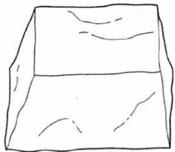
natural_image
Simple line drawing of a 3D rectangular block with visible edges and shading (no text or symbols)4 X75902001
⑤ X75904000
B X75917001
natural_image
Illustration of a rectangular object with three vertical pins and horizontal lines, no text or symbols present.② 122991002
natural_image
Simple line drawing of a rectangular frame with dashed and solid lines indicating edges (no text or symbols)6 X77260000

10 X77128001
③ X76590002
natural_image
Pure mechanical assembly diagram without any text, numbers, or symbols⑦ X75437001

9 X75906001
X77283001
natural_image
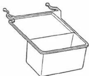
Line drawing of a rectangular container with handles (no text or symbols)③, ⑪ OPTION
③, ⑪ OPTATIVO
The number represents the parts code
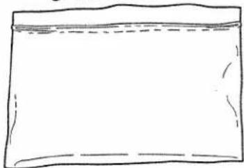
Soft cover
② Accessory bag
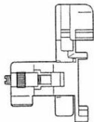
③ Blind stitch foot (OPTION)
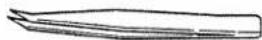
④ Tweezers
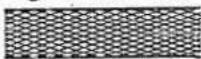
⑤ Thread net (4)
⑥ Thread spool cap (4)
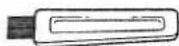
⑦ Screw driver
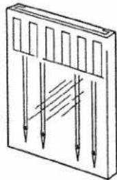
⑧ Needle set: SCHMETZ 130/705H
80/12: 2 pcs.
90/14: 2 pcs.
⑨ Cleaning brush
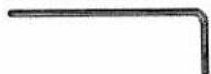
10 Hexagonal (Allen) wrench
⑪ Trim trap (OPTION)
Parts code for presser foot assembly: X76605001
Foot controller: J01780051 (110/120V Area)
J01590051 (220/240V Area)
J01664051(U.K.)
J01665051 (Australia, New Zealand)
J01434051 (Canada)
El número corresponde al código de los elementos
① Funda
② Bolsa de accesorios
③ Prensatelas para puntadas invisibles (OPTATIVO)
④ Pinzas
⑤ Malla (4)
⑥ Tope del carrete (4)
⑦ Destornillador
⑧ Juego de agujas: SCHMETZ 130/705H
80/12: 2 unidades
90/14: 2 unidades
9 Cepillo limpiador
10 Llave de tuerca hexagonal (Allen)
# Orificio de corte (OPTATIVO)
Código de las partes para el ensamblaje del prensatelas: X76605001
Pedal: J01780051 (zona con 110/120V)
J01590051 (zona con 220/240V)
J01664051 (Reino Unido)
J01665051 (Australia, Nueva Zelanda)
J01434051 (Canada)
1
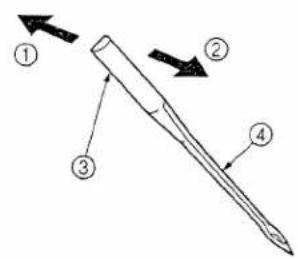
Needle
This machine uses a standard home sewing machine needle.
The recommended needle is SCHMETZ 130/705H.
To remove the needle
(1) Turn the main power switch to the OFF position. (2) Turn the hand wheel toward you by hand until the needle is at its highest position.
(3) Loosen the needle set screw with hexagonal wrench and remove the needle.
① Back
② Front
③ Flat side
④ Groove
To insert the needle
(1) Turn the main power switch to the OFF position.
(2) Turn the hand wheel until the needle bar is at its highest position.
(3) Hold the needle with its flat side away from you and insert it up as far as it will go.
(4) Tighten the needle set screw securely with the hexagonal wrench.
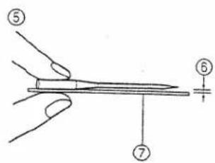
To be sure needle is not bent.
⑤ Place the needle on its flat side and check to see if the space is parallel.
⑥ Flat side
⑦ (needle-plate, glass, etc.)
Aguja
Está máquina funciona con una aguja normal p máquinas domésticas. Así mismo, se recomiend, uso de una aguja SCHMETZ 130/705H.
Para sacar la aguja
(1) Apague el interruptor principal (posición OFF) (2) Gire la ruedecilla con la mano hacia usted hasta que la aguja alcance la posición más elevada (3) Afloje el tornillo de instalación de la aguja con u llave hexagonal y saque la aguja.
① Parte trasera
② Parte delantera
③ Parte Ilana
④ Canal
Para introducir la aguja
(1) Apague el interruptor principal (póngalo en OFI
(2) Gire la ruedecilla hasta que la barra de la agu alcance la posición más alta.
(3) Sujete la aguja con la parte curvada de cara a v e insertela hacia arriba hasta el tope.
(4) Vuelva a apretar firmemente el tornillo de instal ción de la aguja con la llave hexagonal. Para asegurarse de que la aguja no está doblad
⑤ Coloque la aguja en su parte llana y cor pruebe que el espacio sea paralelo.
⑥ Parte llana
⑦ Placa de aguja (Vidrio, etc.)
NOTE:
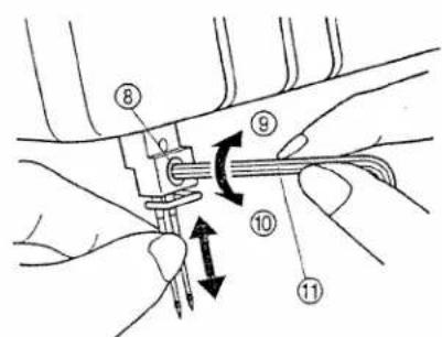
Two-needle models
- On two-needle models, we suggest you hold the two needles with one hand and then insert them both at the same time.
- If the needles have been inserted correctly, the right needle should be set slightly lower than the left one.
CAUTION
The needle set screw holds both needles. Keep this in mind when you loosen the set screw to exchange one or both needles.
⑧ Needle set screw
⑨ Tighten
⑩ Loosen
⑪ Hexagonal wrench
NOTA:
Modelos de dos agujas
- En los modelos de cos agujas, le sugerimos sujetar ambas agujas en una sola mano e insertarlas simultáneamente.
- Si las agujas fueron introducidas correctamente, la aguja de derecha debería quedar un poco más abajo de la izquierda.
PRECAUCION
El tornillo de instalación de las agujas sujeta ambas agujas. No se lo olvide al aflojar dicho tornillo para cambiar una o ambas agujas.
⑧ Tornillo de instalación de las agujas
⑨ Apretar
⑩ Aflojar
⑪ Liave de tuerca hexagonal
natural_image
Pure technical line drawing of a mechanical component without any text, numbers, or symbols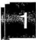
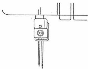
Turning direction of motor
- The motor and hand wheel of this machine turn in a counterclockwise direction (direction of arrow). This is the same direction as an ordinary home sewing machine.
① Hand wheel
Para cambiar la direccion del motor
- El motor y la ruedecilla de esta máquina funcionan en el sentido contrario al de las manecillas del reloj (dirección de la flecha), como es el caso con la mayoría de las máquinas de coser domésticas.
① Ruedecilla
natural_image
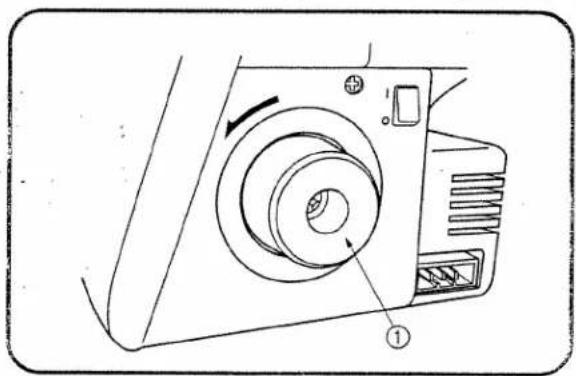
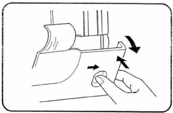
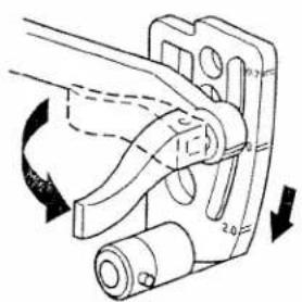
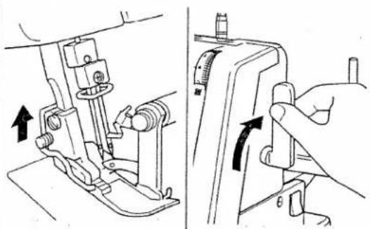
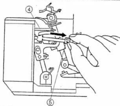
Technical line drawing of a camera with labeled parts (no text or symbols)Opening and closing the front cover
It is necessary to open the front cover when threading this machine.
To open, push the lever to the right and pull the cover down and toward you.
To close, lift cover and push toward the serger until it snaps closed.
NOTE:
For your safety, make sure that the front cover is closed when operating the machine.
Abre y cierre de la tapa delantera
Es necesario abrir la tapa delantera para enhebrar la máquina.
Para abrir, empuje la palanca hacia la derecha y tire la tapa hacia abajo y hacia usted.
Para cerrar, levante la tapa y empújela hacia la máquina de coser hasta que sienta el engancho de cierre.
NOTA:
Para su propia seguridad, averigue siempre que la tapa delantera esté bien cerrada antes de hace funcionar la máquina.
natural_image
Illustration of a hand pressing down on a mechanical component with directional arrows indicating motion (no text or symbols)Operating
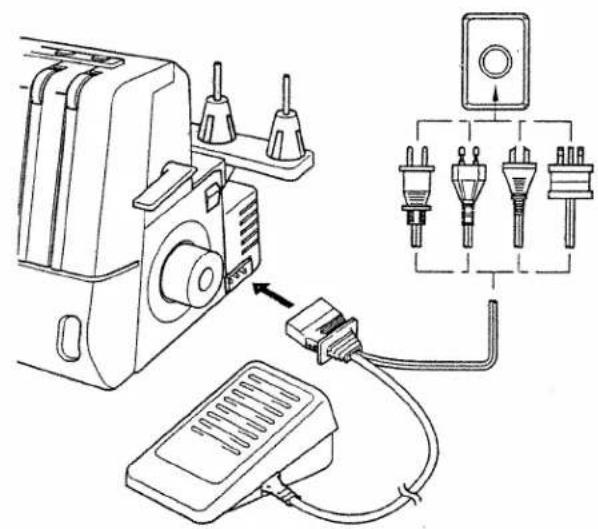
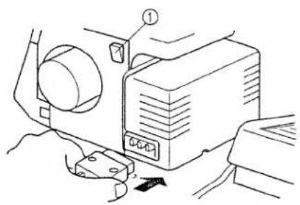
Powering the machine
Preparation
- Insert the three-pin plug into the socket on the bottom right side of the machine. Insert the power supply plug into a power outlet.
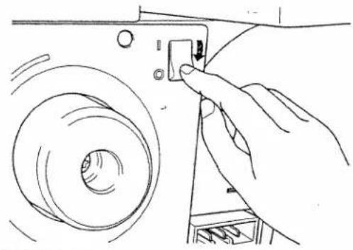
Main Power and Sewing Light Switch
This switch turns the power and sewing light on or off. To turn on push toward "1" mark. To turn off push toward "0" mark.
① Main power and sewing light switch
Operation
When the pedal is pressed lightly, the machine runs at a low speed. As the pedal is pressed further, the machine will increase speed. When the pedal is released, the machine stops.
② Foot control
Funcionamiento
Encendido de la máquina
Preparación de la máquina
- Introduzca el zócalo de tres puntas en el enchufe que se encuentra abajo, en el lado derecho de la máquina e inserte el zócalo de alimentación en una toma de corriente.
Interruptor principal y de luz
Este interruptor permite apagar y encender la máquina así como la luz. Para encender, empuje hacia la marca "1"; para apagar, póngalo en la marca "0".
① Interruptor principal y de luz
Funcionamiento
Al oprimir ligeramente el pedal, la máquina funcionará a baja velocidad. A medida que se apriete más, la máquina incrementará su velocidad. La máquina se parará tan pronto como se suelte el pedal.
② Pedal
natural_image
Line drawing of a projector with hands operating it (no text or symbols)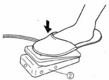
natural_image
Diagram of a foot pressing a button on a mechanical device, with an arrow indicating motion (no text or symbols present)
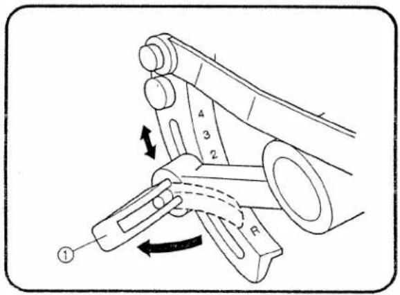
Stitch Length
To change the stitch length,
(1) Open the material plate cover on the left side of the machine.
(2) Pull out the stitch length adjustment lever to release it.
(3) Move the lever to the proper stitch length position.
(4) Push in the adjustment lever to the locked position. You can adjust the stitch length from a minimum 2 mm (1/8 inch) to a maximum 4 mm (5/32 inch).
(5) Close the material plate cover.
The normal stitch length setting is 2.5 mm to 3 mm.
① Stitch length adjustment lever
Largo de puntada
Para cambiar el largo de las puntadas:
(1) Abra la tapa de la placa de tejido en el lado izquierdo de la máquina.
(2) Saque la palanca de ajuste del largo de puntadas para soltarla.
(3) Colóquela en la posición deseada.
(4) Empuje la palanca de ajuste hacia adentro, hasta que alcance su posición de bloqueo. El largo de las puntadas puede ajustarse en cualquier valor entre 2 mm (mínimo) y 4 mm (máximo).
(5) Cierre la tapa de la placa de tejido.
Un ajuste normal para el largo de las puntadas se sitúa entre 2,5 y 3 mm.
① Palanca de ajuste del largo de puntadas
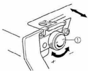
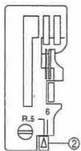
Stitch Width
- The width is factory set to 5mm (3/16 inch). To increase stitch width, turn the dial toward the +. You can adjust the stitch width from 5mm (3/16 inch) to 6mm (1/4 inch). The normal stitch width setting for regular overlock stitch is 5mm (3/16 inch).
① Stitch width dial
② Stitch width indicator
Ancho de puntada
- El ancho de las puntadas está establecido en la fábrica en 5 mm. Para aumentar el ancho de las puntadas, gire el disco hacia el +. Sin embargo se puede ajustar entre 5 y 6 mm. El ajuste normal del ancho de puntada para una puntada overlock corriente es de 5 mm.
① Botón de anchura de las puniadas
② Indicador de ancho de puntadas
9
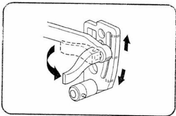
Instructions for the Differential Feed Mechanism
This serger is equipped with two sets of feed teeth under the presser foot to move the fabric through the machine. The differential feed controls the movement of both the front and the rear feed teeth. When set at 1, the feed teeth are moving at the same speed (ratio of 1). When the differential feed ratio is set at less than 1, the front feed teeth move slower than the rear feed teeth, stretching the fabric as it is sewn. This is effective on lightweight fabric that may pucker. When the differential feed ratio is set at greater than 1, the front feed teeth move faster than the back feed teeth, gathering the fabric as it is sewn. This function assists in removing the rippling when serging stretch fabrics and is used for gathering and easing.
• How to adjust the differential feed ratio
(1) Open the material plate cover on the left side of the machine.
(2) Pull out the differential feed adjusting lever.
(3) Adjust the feed as required by the sewing application.
(4) Push in the adjusting lever.
(5) Close the material plate cover.
Instrucciones para el mecanismo de alimentación con diferencial
Esta máquina de coser está provista de dos series de dientes de alimentación debajo del prensatelas, para guiar el tejido por la máquina. El alimentador con diferencial controla los movimientos de los dientes delanteros y traseros. Al ajustarlo en 1, todos los dientes se desplazarán a una velocidad idéntica (relación de 1). Al ajustar la relación del alimentador con diferencial en menos de 1, los dientes delanteros van a moverse más despacio que los traseros, estirando el tejido a medida que se cose. Esta operación resulta muy eficiente al coser materiales finos que pueden arrugarse. Cuando el alimentador con diferencial está ajustado en un valor superior a 1, los dientes delanteros van a moverse más rápido que los dientes traseros, juntando el tejido a medida que se cose. Esta función permite quitar las arrugas al coser tejidos que se estiran y sirve también para fruncir un tejido o facilitar la costura de partes difíciles.
- Como ajustar la relación de alimentación del diferencial
(1) Abra la tapa de la placa de tejido en la parte izquierda de la máquina.
(2) Saque la palanca de ajuste de alimentación del diferencial.
(3) Ajuste la velocidad de alimentación como lo requiere la función de costura usada.
(4) Empuje la palanca de ajuste hacia adentro.
(5) Cierre la tapa de la placa de tejido.
natural_image
Mechanical assembly diagram showing a clamping mechanism with rotational arrows (no text or labels)4
| Diff-feed setting | Main feed (rear) | Differential feed (front) | Effect | Application |
| 0.7 - 1.0 | 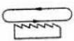 |  | Material is held tight. | Prevents thin materials from puckering |
| 1.0 | 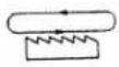 | 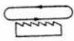 | Without differential feed. | Normal sewing |
| 1.0 - 2.0 | 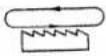 | 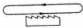 | Material is gathered or pushed together. | Prevents stretch materials from stretching or puckering, gathers light weight materials. |
| Ajustes de alimentación del diferencial | Alimentador principal (detras) | Alimentador con diferencial (delante) | Efecto | Uso |
| 0,7 - 1,0 | 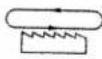 |  | Se mantiene el tejido contraído. | Impide que los tejidos finos frunzan. |
| 1,0 | 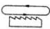 | 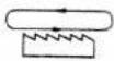 | Sin alimentación con diferencial. | Costura normal. |
| 1,0 - 2,0 | 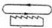 | 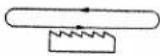 | El tejido se contrae o se junta. | Impide que los tejidos extensibles se estiren o frunzan, contrae los tejidos ligeros. |
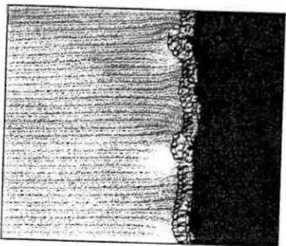
• An example where adjustment is required
When stretch material is sewn without using the differential feed, the edge will be wavy.
- Ejemplo en que se requiere ajuste
Al coser tejidos extensibles sin utilizar una alimer ción con diferencial, su borde va a ser oleado.
4
To make the edge more smooth, adjust the differential feed from 1.0 toward 2.0.
(The exact setting depends on the elasticity of the material.)
The more elastic the material, the further toward 2.0 the differential feed should be set. Test sew with a scrap of the fabric to find the correct adjustment.
CAUTION
When sewing thick non-stretchable material such as denim, do not use the differential feed as it may damage the fabric.
Para remediar al problema y mejorar la apariencia de la orilla, ajuste la alimentación del diferencia entre 1,0 y 2,0 (el ajuste exacto dependerá de el elasticidad del material).
Cuanto más elástico el tejido, más hacia 2 se deb poner el ajuste de la alimentación con diferencia Haga una prueba con un pedazo del tejido par encontrar el ajuste correcto.
PRECAUCION
Si debe coser tejidos gruesos que no son elásticos, tales como el tejano, no trabaje con el alimentador diferencial, para no deteriorar el material.
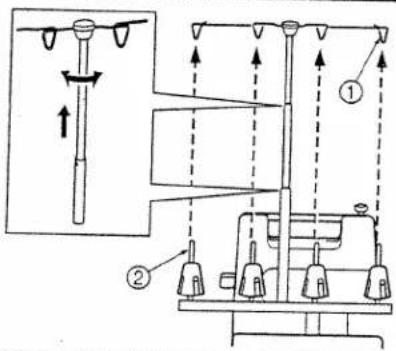
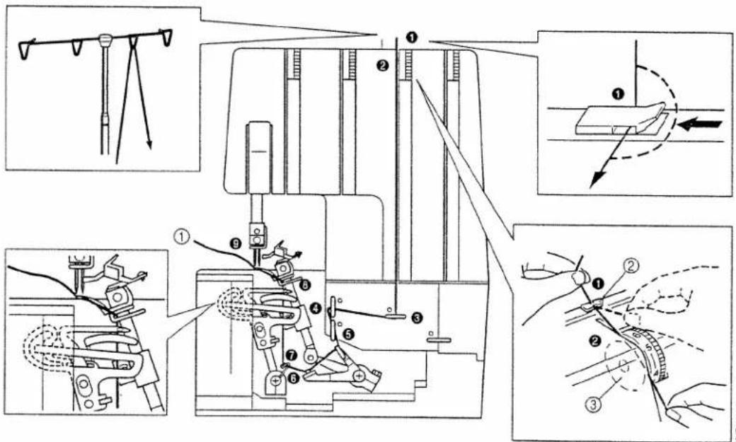
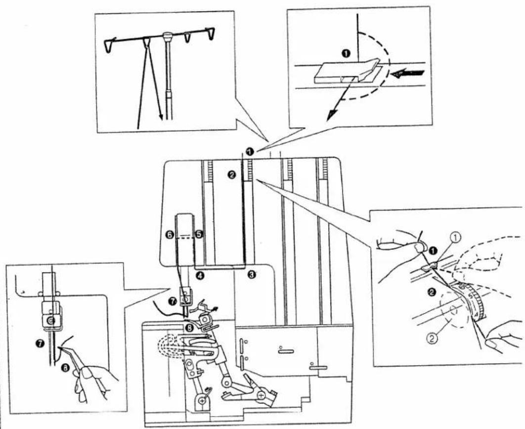
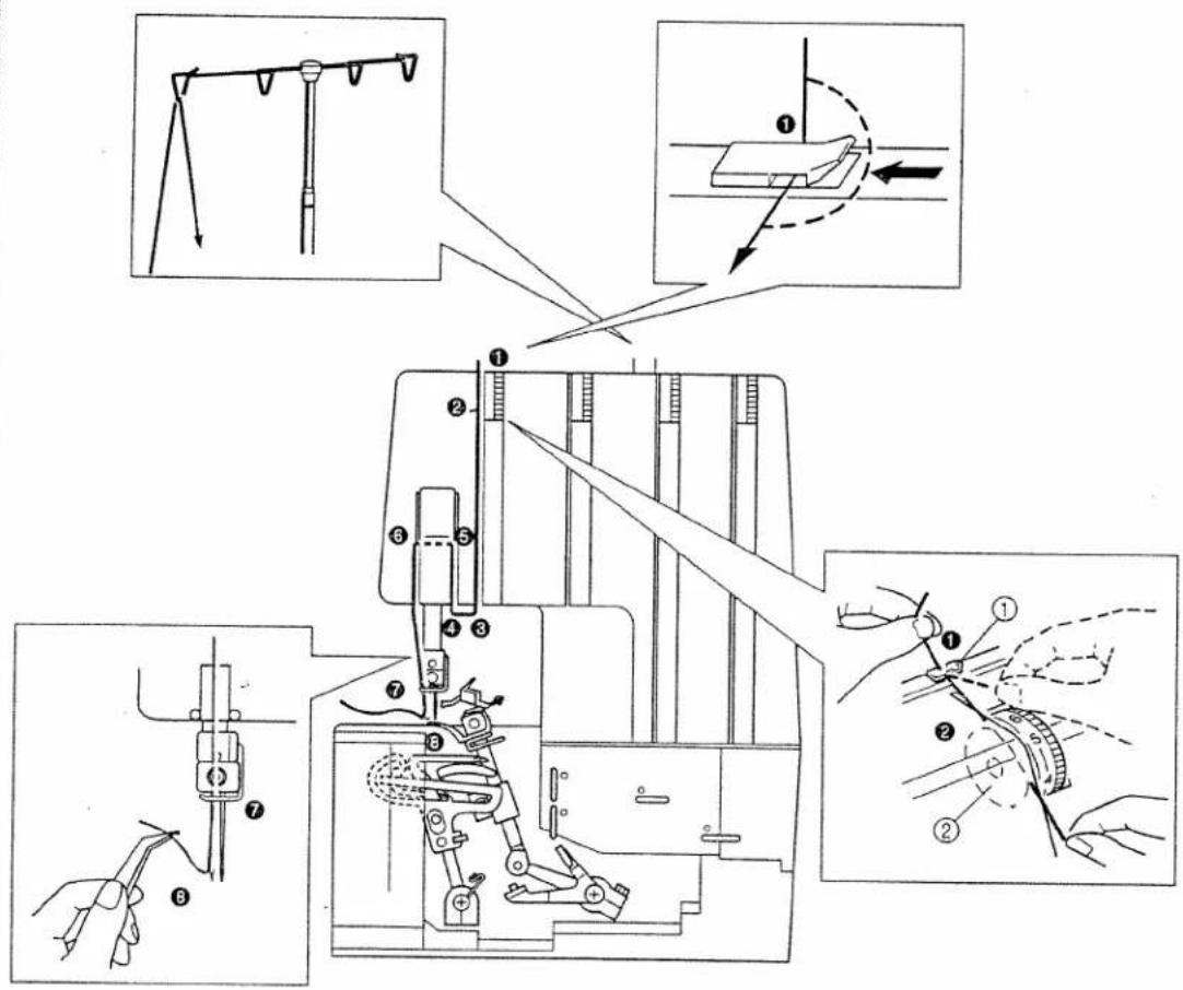
Threading
Preparation
Raise the telescoping thread guide pole to its highest position. Make sure that the thread guides are in alignment above the spool pins.
① Thread guide pole
② Spool pin
③ Correct position
Enhebrado
Preparacion
Levante la barra guía-hilos telescópica a su posición más alta. Compruebe que las guías de hilos queden alineados arriba de los ejes del carrete.
① Barra de guía del hilo
② Eje del carrete
③ Posición correcta
natural_image
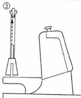
Line drawing of a toilet with a stand and handle, no text or symbols presentHow to use the thread spool cap
When you use standard thread spools, the thread spool cap should be used as illustrated below. Make sure that spool notch is on the bottom.
① Thread spool cap
Como utilizar el tope del carrete
Cuando está utilizando carretes de hilo normales, el tope del carrete debe emplearse tal como se enseña a continuación.
Asegúrese de que la muesca del carrete quede hacia abajo.
① Tope del carrete
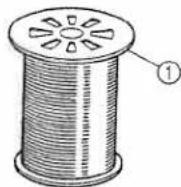
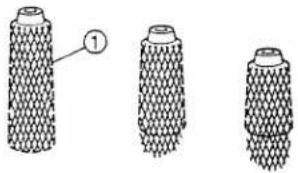
How to use the thread net
If you are sewing with loosely spun nylon thread, we recommend that you cover the spool with the net supplied to prevent the thread from slipping off the spool.
Adapt the net to the shape of the spool (see illustration).
①Net
Como utilizar la ma para hilo
Si está cosiendo con un hilo de hilvanar, le damos cubrir el carrete con la malla pro que el hilo no se deslice del carrete.
Adapte la malla a la forma del carrete.
① Malla
5
natural_image
Three cylindrical objects with textured surfaces, one labeled with number 1 (no text or symbols on objects)Before threading
(1) Turn off the main power switch for safety.
(2) Raise the presser foot using the presser foot lever on the right side of your serger. This opens the thread tension discs so that thread is placed between them. Otherwise thread tension may not be correct.
NOTE
When threading the needle, always be sure to lift the presser foot lever, and also take care to thread in the proper order.
(3) Set the needle bar in its highest position by turning the hand wheel toward you. Turn the hand wheel to find the easiest position for threading, and then thread in the following order upperlooper thread, lowerlooper thread, right needle thread and then the left needle thread.
① Thread tension discs
② Correct
③ Wrong
Antes de enhebrar
(1) Apagar el interruptor principal por seguridad.
(2) Levantar el prensatelas con la palanca que se encuentra a la derecha de la máquina. Esta operación abre los discos de tensión de los hilos para poder colocar el hilo entre ellos. En caso contrario, no se obtendría una tensión de hilos correcta.
NOTA
Al enhebrar la aguja, se debe asegurar de levantar la palanca del prensatelas, y también de enhebrar en el orden correcto.
(3) Colocar la aguja en la posición más alta, girando la ruedecilla hacia afuera.
Girar la perilla hasta encontrar la posición más fácil para enhebrar, y luego enhebrar en el siguiente orden: el hilo del áncora superior, él del áncora inferior, él de la aguja derecha y él de la aguja izquierda.
① Discos de tensión de hilo
② Correcto
③ Incorrecto
natural_image
Line drawing of a hand pressing a button on a device component (no text or symbols)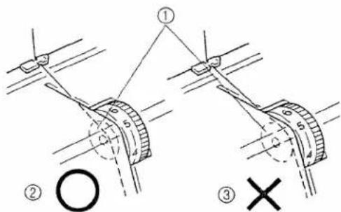
natural_image
Technical illustration of a sewing machine with hand operating the base (no text or symbols present)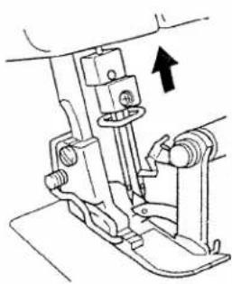
natural_image
Mechanical assembly diagram showing a lever mechanism with an arrow indicating direction (no text or symbols present)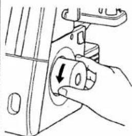
natural_image
Hand holding a circular switch knob with an arrow, no text or symbols present
The proper threading order for this serger is upperlooper, lowerlooper, right needle and left needle.
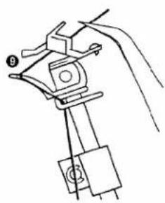
Threading the upperlooper
- Run the thread in the sequence illustrated, following the green color and the numbers next to each threading point.
① Pull the thread about an extra 15 cm (6 inches) through the looper.
② Thread guide
③ Thread tension disc
El orden de enhebrado correcto de esta máquin el siguiente: áncora superior, áncora inferior, ag derecha y aguja izquierda.
Enhebrado del ancora superior
- Enhebre el hilo según ilustrado en la secuen siguiendo el color verde y los números inscrito lado de cada punto de enhebrado.
① Tire unos 15 cm extra de hilo por el ánc
② Guía del hilo
③ Disco de tensión del hilo
natural_image
Line drawing of a hand holding a clamp or clip device with a handle and base (no text or symbols)NOTE:
If the upperlooper thread breaks during sewing This may be caused by the lowerlooper thread getting caught on the upperlooper. If this happens, lower the upperlooper by turning the hand wheel, remove the lowerlooper thread from the upperlooper, and re-thread the upperlooper from at least the tension disk.
NOTA:
Si el hilo del áncora superior se rompe al coser. El hilo del áncora inferior se engancha a veces con el hilo del áncora superior. En este caso, baje el áncora superior girando la ruedecilla, saque el hilo del áncora inferior y vuelva a enhebrar el áncora superior por lo menos hasta el disco de tensión.
natural_image
Technical line drawing of a mechanical assembly with no visible text or symbols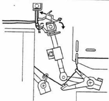
natural_image
Mechanical linkage diagram showing components and motion arrows (no text or labels)
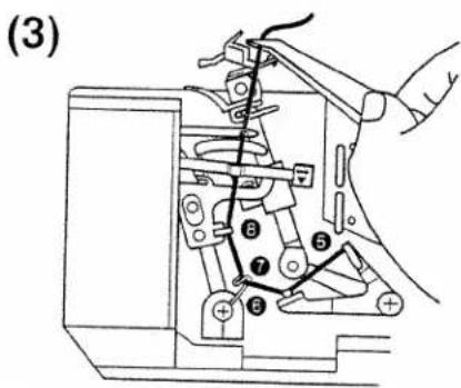
Threading the lower looper
- Run the thread in the sequence illustrated, following the blue color and the numbers next to each threading point.
Enhebrado del áncora inferior
- Enhebre el hilo según lo ilustrado en la secuencia, observando el color azul y los número inscritos al lado de cada punto de enhebrado.
5
① Pull the thread about an extra 15 cm (6 inches) through the looper.
② Thread guide
③ Thread tension disc
NOTE:
If the lowerlooper thread breaks during sewing, cut and remove thread from both of the needles. Before re-threading the lowerlooper, make sure that the lowerlooper re-threading is done exactly as diagrammed above. The machine will not operate properly if the threading is not done in the proper sequence.
① Tire unos 15 cm extra de hilo por el ánd
②Guía del hilo
③ Disco de tensión del hilo
NOTA:
Si el hilo del áncora inferior se rompe al co Antes de volver a enhebrar el áncora infer asegúrese de que el enhebrado se haya real do tal como se enseñó en el diagrama arriba máquina no funcionará correctamente si no a enhebrada en el orden apropiado.
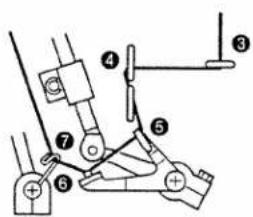
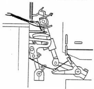
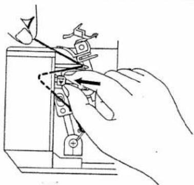
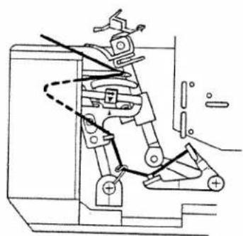
Lowerlooper Threader
(1) Slide the lowerlooper-threading lever to the right.
(2) Position the thread into the hook (left end) of the threading lever.
(3) Place the thread through the eye of the lower looper.
(4) Holding the end of the thread, slide the lower looper threading lever to the left which returns it to its standard position.
(5) Make sure that the red triangle marks line up.
NOTE
When moving the lowerlooper threading lever to the left, always make sure that the two red triangle marks line up as illustrated.
④ Lowerlooper
⑤ Lowerlooper threading lever
NOTE
Thread the needles after the lowerlooper and upperlooper have been threaded.
Enhebrador del áncora inferior
(1) Deslice la palanca de enhebrado del áncora inferior hacia la derecha.
(2)Coloque el hilo dentro del corchete (extremo izquierdo) de la palanca de enhebrado.
(3) Pase el hilo por el ojo del áncora inferior.
(4) Mientras sujete el extremo del hilo, deslice la palanca de enhebrado del áncora inferior hacia la izquierda para que vuelva a su posición normal.
(5) Asegúrese de que las marcas en forma de triángulo rojo queden bien alineadas.
NOTA
Al mover la palanca del áncora inferior hacia la izquierda, averigue siempre que los dos triángulos rojos coincidan el uno con el otro, tal como ilustrado.
④ Ancora inferior
⑤ Palanca del áncora inferior
NOTA
Enhebre siempre las agujas después de haber enhebrado las áncoras superior e inferior.
(1)
(2)
(4)
natural_image
Illustration of a hand using a tool to adjust or install a mechanical component (no text or symbols visible)(5)
natural_image
Technical line drawing of a mechanical assembly with no visible text or symbols
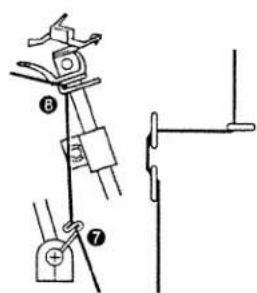
Threading the right needle
- Run the thread in the sequence illustrated, following the red color and the numbers next to each threading point.
① Thread guide
② Thread tension disc
Enhebrado de la aguja derecha
- Enhebre la aguja tal como ilustrado en la secuencia, respetando el color rojo y los números insertos al lado de cada punto de enhebrado.
① Guía del hilo
② Disco de tensión del hilo
5
Threading the left needle
- Run the thread in the sequence illustrated, following the orange color and the numbers next to each threading point.
① Thread guide
② Thread tension disc
Enhebrado de la aguja izquierda
- Enhebre la aguja tal como ilustrado en la secuencia, respetando el color naranja y los números inscritos al lado de cada punto de enhebrado.
① Guía del hilo
②Disco de tensión del hilo
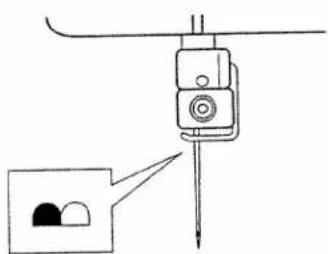
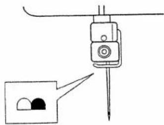
Setting for Two-thread Overlock Stitch Sewing
Sew with lowerlooper and one needle only.
Thread in the following order
(1) Lowerlooper thread (blue). (See pages 19-20.)
(2) Left needle thread (orange) for wide 2-thread ① or right needle thread (red) for normal 2-thread
②. (See page 21 or 22.)
①Left needle for wide 2-thread
② Right needle for narrow 2-thread
(3) Lower the two-thread converter lever to allow two thread sewing.
For two-thread sewing
③ Lower the two-thread converter lever
To return to three- and four-thread sewing
④ Raise the two-thread converter lever
Ajuste para coser con puntada overlock de dos hilos
Costura con el áncora inferior y una sola aguja.
Enhebrar en el siguiente orden
(1) Hilo del áncora inferior (azül). (Véanse las pági nas 19-20).
(2) Hilo de la aguja izquierda (naranja) para costuras de dos hilos anchas ① o hilo de la aguja derecha (rojo) para costuras de dos hilos normales ② (Véase la página 21 ó 22).
① Aguja izquierda para costuras de dos hilo anchas.
② Aguja derecha para costuras de dos hilo estrechas.
(3) Bajar la palanca de conversión para dos hilos co el fin de poder coser con dos hilos.
Para coser con dos hilos
③ Bajar la palanca de conversión para de hilos.
Para volver a coser con tres o cuatro hilos
④ Subir la palanca de conversión para do hilos.
①
②
natural_image
Diagram of a mechanical device with a pointed tip and two circular components, no text or symbols present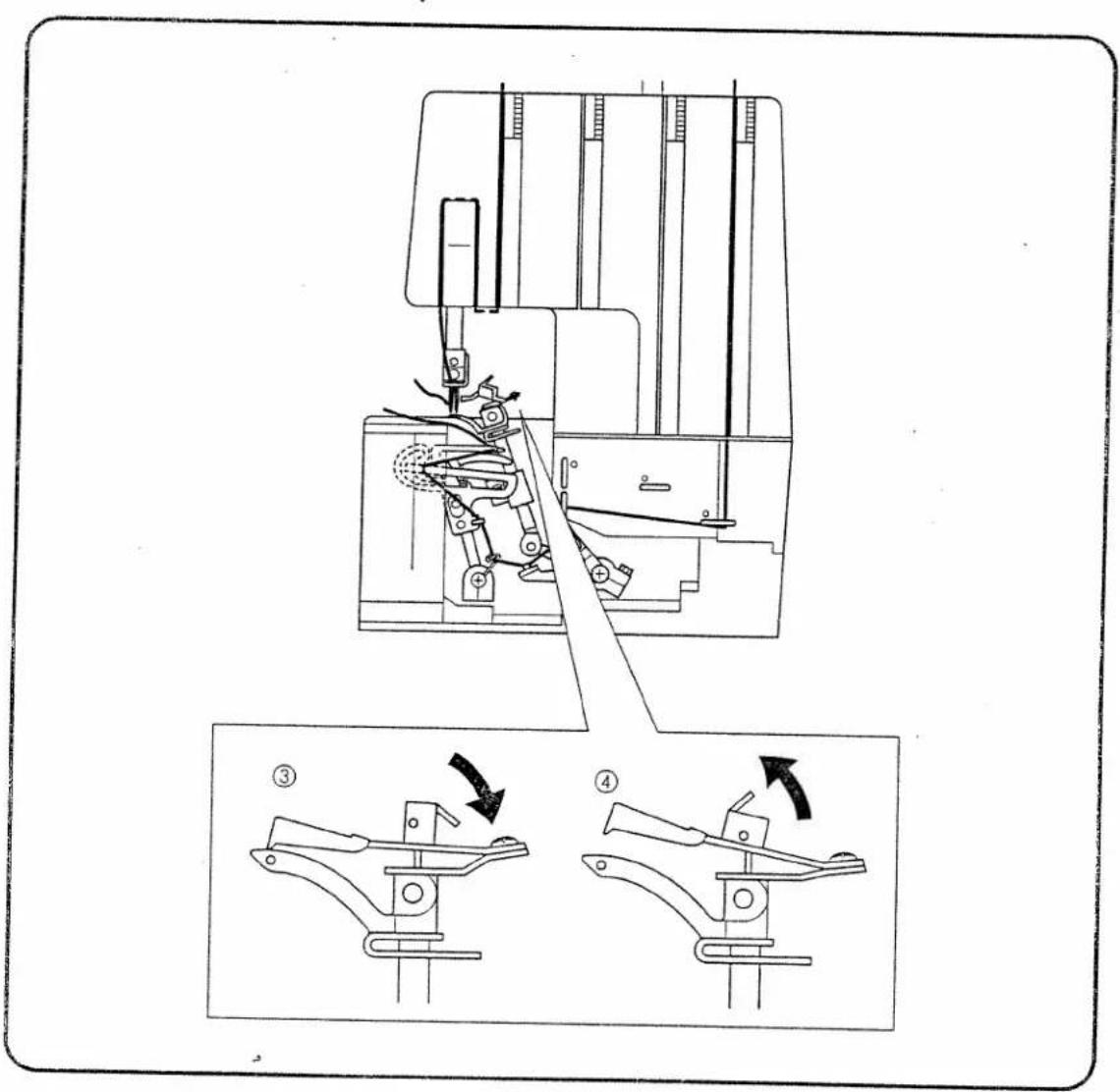
Comparison Chart of Sewing Materials, Threads and Needles
| Material | Stitch | Stitch Length (mm) | Thread | Needle | |
| Light materials | Crepe de chine Georgette Lawn Organdy Tricot | Overlock stitch | 2.0-3.0 | Spun : #80 Cotton : #80-100 Silk : #80-100 | SCHMETZ 130/705H #70 #80 |
| Light materials | Crepe de chine Georgette Lawn Organdy | Narrow/rolled edge stitch | Shorter than 2.0 | Needle thread Polyester: #80 Nylon : #80 Looper thread Polyester: #80 Nylon : #80 Woolly nylon thread | SCHMETZ 130/705H #70 #80 |
| Medium materials | Poplin Gingham Seersucker Gabardine Serge Knitted | Overlock stitch | 2.5-3.5 | Spun : #60-80 Cotton : #60-80 Silk : #50-80 Nylon : 50-80 Polyester: #50-80 | SCHMETZ 130/705H #80 #90 |
| Heavy materials | Cashmere Tweed Denim Jersey | Overlock stitch | 3.0-4.0 | Cotton : #40-60 Silk : #40-60 Polyester: #30-60 Nylon : #30-60 | SCHMETZ 130/705H #90 |
NOTE:
Thread decorative thread in the upperlooper for fashion sewing.
Tabla de relación entre los distintos tejidos, hilos y agujas
| Tejido | Puntada | Largo de puntada (mm) | Hilo | Aguja | |
| Tejidos finos | Crepe de ChinaGeorgetteLinoOrgandíTricot | Puntadas Overlock | 2,0 - 3,0 | Hilo de hilvanar : n°80Algodón : n°80 - 100Seda : n°80 - 100 | SCHMETZ130/705Hn°70n°80 |
| Tejidos finos | Crepe de ChinaGeorgetteLinoOrgandí | Puntada es-trecha/de bordeenrolla-do | Más corto que 2,0 | Hilo de las agujas Poliester : n°80Nilón : n°80Hilo del áncora Poliester : n°80Nilón : n°80Hilo de nilón tipo lana | SCHMETZ130/705Hn°70n°80 |
| Tejidos medios | PopelinaGuingaCrespón de algodónGabardinaSargaPrendas de punto | Puntadas Overlock | 2,5 - 3,5 | Hilo de hilvanar : n°60 - 80Algodón : n°60 - 80Seda : n°50 - 80Nilón : 50 - 80Políester : n°50 - 80 | SCHMETZ130/705Hn°80n°90 |
| Tejidos gruesos | CachemirTweedTejanoJersey | Puntada Overlock | 3,0 - 4,0 | Algodón : n°40 - 60Seda : n°40 - 60Políester : n°30 - 60Nilón : n°30 - 60 | SCHMETZ130/705Hn°90 |
NOTA:
Enhebre el áncora superior con hilo decorativo para la costura de prendas de moda.