DADM-CK-90-8 - Ukategoriseret Festo - Gratis brugsanvisning og manual
Find enhedens vejledning gratis DADM-CK-90-8 Festo i PDF-format.

Brugerspørgsmål om DADM-CK-90-8 Festo
0 spørgsmål om dette apparat. Besvar dem du kender, eller stil dit eget.
Stil et nyt spørgsmål om dette apparat
Download vejledningen til din Ukategoriseret i PDF-format gratis! Find din vejledning DADM-CK-90-8 - Festo og tag din elektroniske enhed tilbage i hånden. På denne side er alle dokumenter nødvendige for brugen af din enhed offentliggjort. DADM-CK-90-8 af mærket Festo.
BRUGSANVISNING DADM-CK-90-8 Festo
Assembly instructions (Original: de)
8059334
1604c [8059336]
Indexing conversion kit
DADM-CK
FESTO
Festo SE & Co. KG
neaf
73726 EssIngen
Germany
+49711307-0
1. Parts lists
1a. Parts list DADM-CK-65/-90
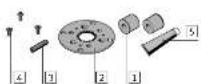
1 Spacing bolt
2 Index plate
□ Stop non
4 Screw
15 Special grease
(free of silicopan)
1b. Parts list DADM-CK-140/-220
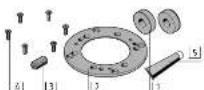
1 Spacing bolt
2 Index plate
Stop bolt
4 Screw
Special grease
LUB-E1
(free at silicone)
1c. Not in scope of delivery
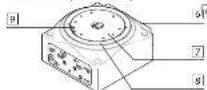
Rotary indexing
table DHTG
7 Rotating plate
Clamping ring
19 Screw
(2x)
(1x)
(1x)
[3x]
[1x]
[Non-Text]
[Non-Text]
[Non-Text]
(2x)
(1x)
(10)
[63]
[10]
[Non-Text]
[Non-Text]
(1)
(四)
[1x]
[1x]
(1x)
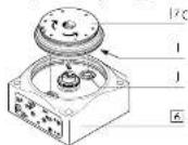
5. Mounting
5a. Disassembly of the rotary table 7
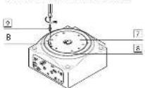
- Mark the rotary table 7 and
the clamping ring 8 at the
natch (B) that corresponds
to the countersink of the
screw 9.
• Unlighten screw [9]
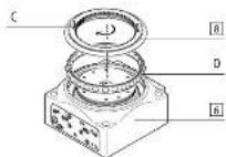
C
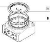
- Turn open the clamping
ring with the help of
2 cylindrical dowel
pins (C)
Sizes for cylindrical dowel,
pins (L):
OHIO-63: 2 x 2HB
DHTG-90 = -2202 2 x 5m6
- Remove the Laged ball breacing (D)
Boring (5)
- Full the r cavity made 7
of 2 seconds (F)
Thread for screen (E)
DHTG-65/90:MA
DH16-14D-M6
DH16-220-M8
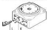
- Turn the rotating plate 2 ,
F
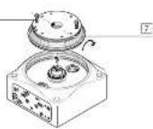
• Full the rotary table 7
up and out with the help
of 2 screws (L) , Shared frequency (F)
Through for stocks (L): DUTC 6:00 AM
DH16-147- M6
DH16-728-M8
- Turn the rotating plate 7 .
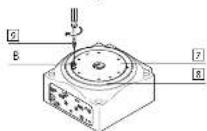
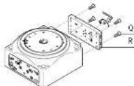
5b. Assembly of the Index plate 4.

F. Unscrew screws (F).
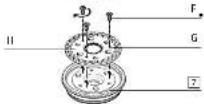
F. Tighten the screws (F) in the
threads (G).
• Force away the index
plate (H) from the rotating
plate 7 by means of the
screws (Γ).
- Position the index plate 2
on the rotating plate?
- Fasten the index plate 2
with the screws 4
图 1
Plan on the industry staff
- Observe the index holes (i). Turn the rotation plate
- 10.11 and 10.20 (place)
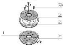
5c. Assembly of the rotary table 7
7 Check: The index holes (i) are
located above the index
1 bolts (J).
- Place the rotating plate [7]
on the rotary indexing ta-
ble 6.
^31 The cylindrical doseal ions (C) are cut into the scope of delivery.
^1 The screws (E) are not included in the scope of delivery.
- Place the ball bearing
cage (D) in the rotary index
ing table 6.
- Tighten the clamping ring
by means of the cylindrical
dowel pins (C).
- Untighten and remove the
Leymouthal lower pins (C).
Check: The marks on the
rotating plate 7 and on the
clamping ring 8] match at
the notch (B)
- Tighten screw [9].
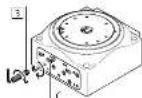
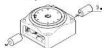
5d. Assembly of spacing bolt 1
- Turn open the clamping
component (K) by 1 turn.
- Unscrew the stop screw (L).
2019年1月1日,公司召开2019年第一次临时股东大会,并通知全体董事。
[Non-Text]
(五) 2017年1月1日
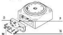
- Unscrew flow control
valve (M).
- Unlighten screw (N).
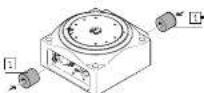
- Carefully remove the sub-
base (0). Make sure not to
lose the compression
spring (P) and the seals.
• Upscrew screws (D).
- Carefully remove the stop
plate (R). Make sure not to
lose the seals.
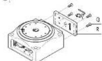
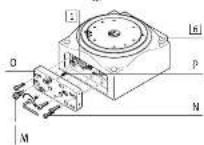
- Screw in and tighten the
throttle valve (M).
Check: Correct fit of the seals.
- Fasten the stop plate (R) us
ing the screws (Q).
- Screw in the existing stop
bolt 3 (→ Section 7).
Check: The required cushion-
ing is achieved.
- Tighten the clamping com-
ponent (K).
- Pressurise the rotary indexing table [6].
The rotary table must not turn freely.
To lock:
- Pressurise port "8" with minimum 4 bar.
If the rotary table 7 is still rotating freely:
- Manually turn the rotary table 7 until the index bolts (i) engage.
- Screw sizes and tightening torques M. ^51
| DADM:CK- | 65 | 90 | 140 | ||
| (K) Clamping component | <2 | 2.5 | 4 | ||
| [Nm] | 0.8 | 2.5 | |||
| (K) Flow control valve | GRLA-M5-B GRLA-C18 | ||||
| [Nm] | 1.5 | 5.5 | |||
| (0) Screw | Mx26 | Mx26 | Mx25 | ||
| [Nm] | 3 | 10 | |||
| (0) Screw | Mx36 | Mx36 | Mx36 | Mx30 | |
| [Nm] | 1.5 | 3 | 6 | ||
| △ Screw | Mx8 | Mx32 | Mx36 | Mx36 | |
| [Nm] | 2 | 4 | 7 | ||
| ▽ Screw | Mx36 | ||||
| [Nm] | 0.6 | ||||
- Lengths of the split pins 1 and stop bolts 3
| DADM-CX- | 65 | 90 | 140 | 220 | ||
| Spacing | Pin | |||||
| 3 | [1] | [mm] | — | — | — | — |
| [3] | [mm] | 12 | 12 | — | ||
| 3 | [1] | [mm] | 11.31 | 15.71 | — | — |
| [3] | [mm] | 23.3 | 28 | 41 | 59 | |
| 4 | [1] | [mm] | 16.96 | 23.66 | 12.57 | 25.13 |
| [3] | [mm] | 29 | 35.5 | 26.3 | 44.1 | |
| 6 | [1] | [mm] | 12.62 | 31.42 | 25.13 | 50.27 |
| [3] | [mm] | 34.6 | 63.5 | 39 | 69.3 | |
| 8 | [1] | [mm] | 25.45 | 35.34 | 31.62 | 62.81 |
| [3] | [mm] | 37.5 | 47.5 | 45.5 | 81.8 | |
| 12 | [1] | [mm] | 28.27 | 39.27 | 37.7 | 75.4 |
| [3] | [mm] | 60.3 | 51.5 | 51.5 | 96.4 | |
| 24 | [1] | [mm] | 11.1 | 43.2 | 41.98 | 87.97 |
| [3] | [mm] | 45 | 55.5 | 58 | 107 | |
- Prior to commissioning
Cushioning setting and commissioning (→ applicable document).
- In terms of the following (see 10) without tolerance details
M_n > 0.5 1, Area × 30%
M_n > 1 No: ±20%
2. Intended use
Indexing conversion kit DADM-CK:
Conversion of the rotary indexing table 6 to a different spacing.
3. Safety instructions and notes on mounting
- Switch off compressed air before mounting work.
- Exhausting rotary indexing table 5.
• Observe lightening torques (→ Section 6).
i Information copies
Applicable documents → www.festo.com/sp
→ Rotary indexing table DHTG operating instructions
→ Assembly instructions for energy throughfeed DHTG-P4
4. Preparations for mounting
- Disassemble the energy throughfeed DHTG-P4 (→ applicable documents).
- Grease all movable parts of the indexing conversion kit using the
grease 5
The rotary table 7 must be turning freely.
To unlock
- Pressurise port "A" with minimum 4 bar.
^1 WITH DADM-CK-65-2, DADM-CK-90-3, DADM-CK-40-3, DADM-CK-720-3 there are no soaring but.s ± included in the scope of delivery ( Section 7).
7 Check: The index holes (i) are
located above the index
1 bolts (J).
in the scope of delivery.
- Place the rotating plate [7]
on the rotary indexing ta-
ble 6.
Remove the split pins (S)
from the hole to their left.
^29 Without the split pin mounted, no counter pressure is acting on the compression spring (P), which causes function failure of the rotary indexing table.
^5 Tolerance for tightening forces M_s without tolerance details
M_n > 0.6 1, Size × 30%
M_n > 1. No: ±20%