SPTE-P10R-S6-B-2.5K - Ukategoriseret Festo - Gratis brugsanvisning og manual
Find enhedens vejledning gratis SPTE-P10R-S6-B-2.5K Festo i PDF-format.

Brugerspørgsmål om SPTE-P10R-S6-B-2.5K Festo
0 spørgsmål om dette apparat. Besvar dem du kender, eller stil dit eget.
Stil et nyt spørgsmål om dette apparat
Download vejledningen til din Ukategoriseret i PDF-format gratis! Find din vejledning SPTE-P10R-S6-B-2.5K - Festo og tag din elektroniske enhed tilbage i hånden. På denne side er alle dokumenter nødvendige for brugen af din enhed offentliggjort. SPTE-P10R-S6-B-2.5K af mærket Festo.
BRUGSANVISNING SPTE-P10R-S6-B-2.5K Festo
Pressure transmitter SPTE
Operating instructions
Original instructions
8058488
2017-03c
[8058490]
CE
√
For all available product documentation → www.festo.com/pk
1 Operating elements and connections
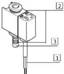
1 Electrical connection
2 Pneumatic connection
3 Blanking plug
Fig. 1
| Feature Order code Specification | ||
| Function SPTE Pressure transmitter | ||
| Pressure measuring range -B2, -B11, -P025, -P05, -P1, -P2, -P6, -P10, -V025, -V05, -V1 | →Technical data | |
| Pressure input R Relative pressure | ||
| Mounting/pneumatic connection | S4 Push-in sleeve 4 mm (insertable) | |
| S6 Push-in sleeve 6 mm (insertable) | ||
| Q3 Push-in connector 3 mm | ||
| Q4 Push-in connector 4 mm | ||
| F Flange (with through-hole and screw) | ||
| PC10 Cartridge 10 mm | ||
| Electrical output B 1 ... 5 V | ||
| V 0 ... 10 V | ||
| Electrical connection | 2.5K | 2.5 m cable, open end |
Fig. 2
2 Function and application
The SPTE pressure transmitter is intended for measuring the relative pressure in pneumatic applications. The SPTE converts pneumatic pressure values into an electrical analogue signal, which can be used for control or regulating functions.
3 Requirements for product use

Note
Incorrect handling can lead to malfunctioning.
- These general conditions for the correct and safe use of the product must be observed at all times.
- Observe the specified limits, e.g. for pressures, forces, temperatures, etc. (→ 9 "Technical data").
- Ensure that there is a supply of correctly prepared compressed air.
- Please observe the prevailing ambient conditions.
-
Please observe the regulations applicable to the place of use (e.g. those of local or national institutions).
-
Remove all transport packing such as protective wax, foils, caps, cardboard boxes.
- Remove everything used for protection during transport such as protective wax, films, caps and cardboard boxes. The individual materials can be stored in containers for recycling purposes.
- The device is intended for industrial use. Measures may need to be implemented in residential areas for interference suppression.
- Remove dirt particles in the supply lines by blowing through the tubing and hoses. In this way you will protect the device from premature failure or heavy wear (→ DIN ISO 4414, section 9.4).
- Please observe the warnings and instructions:
- on the product
– in these operating instructions.
3.1 Range of application and certifications
The information in this section, in combination with the UL marking on the product, must be observed in order for there to be compliance with the certification conditions of Underwriters Laboratories Inc. (UL) for USA and Canada. Observe the following English-language remarks from UL:
For use only in or with complete equipment where the acceptability of the combination is determined by UL LLC. When installed in an end-product, consideration must be given to the following:
- This component has been judged on the basis of the creepage and clearances required in the indicated standards, which would cover the component itself if submitted for listing: UL 61010-1, CAN/CSA 22.2 No. 61010-1.
- The end-product shall consider that the enclosure does not serve as a fire/electrical/mechanical enclosure, the product should be used with enclosure at the end product.
– The output connectors are not investigated for field wiring. - The unit is considered acceptable for use in a max ambient of: 50^ / 122^ .
UL approval information
| Product category code | QUYX2 (USA) or QUXY8 (Canada) |
| File number | E322346 |
| Considered Standards | UL 61010-1CAN/CSA 22.2 No. 61010-1 |
| UL mark |
Fig. 3
4 Installation
4.1 Mechanical and pneumatic

Note
- Mount the SPTE or connect the tubing so that no condensation from the compressed air lines can gather in the device.
It can be fitted in any position. Mount the SPTE as follows:
| SPTE-...-Q... with mounting clip | SPTE-...-Q... | SPTE-...-S... | SPTE-...-F |
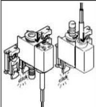 |  | 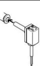 | 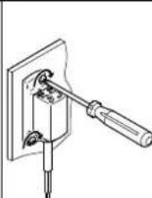 |
| 1. If necessary, shorten the SAMH-8 to the desired number of slots.2. Observe the hole pattern for the SAMH (→ Fig. 10).3. Mount the SAMH with M3 screws (included in the scope of delivery)3).4. Insert the SPTE into the SAMH mounting clip in the direction of the arrow. (Cable outlet at the top or bottom is possible).5. Connect the tubing of the SPTE (→ next column). | Single-ended tubing1. Seal a pneumatic connection on the SPTE with the blanking plug1.2. Connect the tube to the free pneumatic connection.Double-sided tubing1. Remove the blanking plug1.2. Connect the tube to both pneumatic connections. | 1. Insert the pneumatic connection of the SPTE into the push-in fitting as far as possible. | 1. Observe the hole pattern for the flange (→ Fig. 10).2. Check the correct seating of the sealing ring.3. Secure the SPTE in place using two M2 screws (included in the scope of delivery)2). |
1) Tightening torque: max. 0.6 Nm
2) Tightening torque: max. 0.3 Nm
Fig. 4
4.2 Electrical

Warning
Only use power sources which guarantee reliable electrical isolation of the operating voltage as per IEC/EN 60204-1. Also observe the general requirements for PELV power circuits as per IEC/EN 60204-1.

Note
Long signal lines reduce the resistance to interference.
- Make sure that the signal cable is never longer than 30 m.
Circuit diagram
SPTE-...
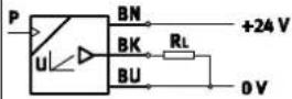
Fig. 5
5 Commissioning and operation
-
Switch on the operating voltage.
-
Pressurise the SPTE with the desired pressure.
At the analogue output, depending on the pressure measuring range, the pressure measurement value is an electrical pressure-proportional signal.

Attention
An increase in temperature above the permissible material temperature of 80 °C can destroy the SPTE.
- Avoid high cycle frequencies with large pressure amplitudes.
6 Maintenance and care
- Switch off the following sources of energy before cleaning the exterior of the device:
- Operating voltage
- Compressed air/vacuum
- Clean the exterior of the SPTE with a soft, dry cloth if required.
7 Disassembly
- Switch off the following sources of energy before dismantling:
- Operating voltage
- Compressed air/vacuum
- Disconnect the respective connections from the SPTE.
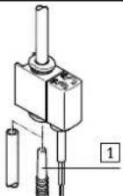
Remove the SPTE-...Q... from the mounting clip
-
Press the lever 1 on the SAMH mounting clip and keep it depressed.
-
Remove the SPTE from the mounting clip in the direction of the arrow.
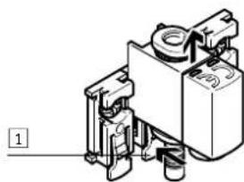
natural_image
Mechanical component diagram showing a valve assembly with no visible text or symbolsFig. 6
8 Troubleshooting
| Malfunction Possible cause Remedy | ||
| No voltage or unexpected voltage at the analogue output | Operating voltage not applied or no permissible operating voltage | Switch on power supply/maintain permitted operating voltage range |
| Connections swapped (incorrect polarity) | Connect the SPTE in accordance with the diagram | |
| Wire break Send the SPTE to Festo with a description of the fault | ||
| Short circuit/overload at analogue output | Eliminate short circuit/overload | |
| Pressure drop/failure Check the pneumatic connection. Eliminate pressure failure | ||
| SPTE operated with non-permitted medium | Replace the SPTE and operate with compressed air only | |
| SPTE defective Send the SPTE to Festo with a description of the fault | ||
Fig. 7
9 Technical data
SPTE
| General | |
| Approval C-Tick, c UL us – Recognized (OL) | |
| CE marking (→ declaration of conformity) | According to EU-EMV-RL1) |
| Note on materials | RoHS-compliant |
| Input signal/measuring element | |
| Measured variable | Relative pressure |
| Operating medium | Compressed air quality class according to ISO 8573-1:2010 [7:7:4], no aggressive gases |
| Temperature of medium [°C]– General | 0...+50 |
| Ambient temperature [°C]– General | 0...+50 |
| Output, general2) | |
| Accuracy [±%FS] | 3 at ambient temperature (approx. 23 °C)4 in ambient temperature range |
| Repetition accuracy [±%FS] | 0.3 |
| Analogue output | |
| Output characteristic curve [V] | SPTE-...-B: 1 ... 5 |
| SPTE-...-V: 0 ... 10 | |
| Rise time [ms] | Typ. 1 |
| Min. load resistance [kohms]of voltage output | 15 |
| Output, additional data | |
| Protection against short circuit | For all electrical connections(also output for pos. supply voltage) |
| Overload protection | Yes |
| Electronic components | |
| Operating voltage range [V DC] | SPTE-...-B: 10 ... 30 |
| SPTE-...-V: 18 ... 30 | |
| Idle current [mA] | Typ. 11 |
| Reverse polarity protection For all electrical connections | |
| Electromechanical components | |
| Electrical connection | Cable, 3-wire, open end |
| Max. permissible cable length [m] | 30 |
| Materials – cable sheath | PVC |
| Mechanical components | |
| Mounting position | Any; avoid condensation gathering in the SPTE |
| Product weight [g] | approx. 35 (incl. cable 2.5 m) |
| Housing material | Reinforced PA |
| Immissions/emissions | |
| Storage temperature [°C] | -20 ... +80 |
| Protection class | IP40 |
| Electrical protection class | III |
| Shock resistance | Severity level 2 as per EN 60068-2-27(Half sine 30g, 11 ms) |
| Vibration resistance | Severity level 2 as per EN 60068-2-6(10 ... 60 Hz: 0.35 mm / 60 ... 150 Hz: 5g) |
1) Measures may need to be implemented in residential areas for interference suppression.
2) %FS (fullscale) = measuring range or range of the output characteristic
Fig. 8
| SPTE- | B2 | B11 | V025 | V05 | V1 | P025 | P05 | P1 | P2 | P6 | P10 | |
| Pressure measuring range | ||||||||||||
| Starting value | [bar] | -1 | 0 | |||||||||
| [MPa] | -0.1 | 0 | ||||||||||
| Final value | [bar] | 1 | 10 | -0.25 | -0.5 | -1 | 0.25 | 0.5 | 1 | 2 | 6 | 10 |
| [MPa] | 0.1 | 1 | -0.025 | -0.05 | -0.1 | 0.025 | 0.05 | 0.1 | 0.2 | 0.6 | 1 | |
| Overload range | ||||||||||||
| Starting value | [bar] | -1 | ||||||||||
| [MPa] | -0.1 | |||||||||||
| Final value | [bar] | 5 | 15 | 1 | 2 | 5 | 1 | 2 | 5 | 6 | 15 | 15 |
| [MPa] | 0.5 | 1.5 | 0.1 | 0.2 | 0.5 | 0.1 | 0.2 | 0.5 | 0.6 | 1.5 | 1.5 | |
Fig. 9
10 Appendix
Hole patterns for flange SPTE-...-F1) and mounting clip SAMH
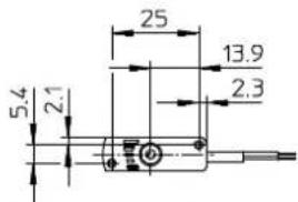
1) Pressure connection hole: ∅ 2 mm max.
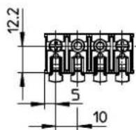
Fig. 10