YXML-2 - Ukategoriseret Festo - Gratis brugsanvisning og manual
Find enhedens vejledning gratis YXML-2 Festo i PDF-format.

Brugerspørgsmål om YXML-2 Festo
0 spørgsmål om dette apparat. Besvar dem du kender, eller stil dit eget.
Stil et nyt spørgsmål om dette apparat
Download vejledningen til din Ukategoriseret i PDF-format gratis! Find din vejledning YXML-2 - Festo og tag din elektroniske enhed tilbage i hånden. På denne side er alle dokumenter nødvendige for brugen af din enhed offentliggjort. YXML-2 af mærket Festo.
BRUGSANVISNING YXML-2 Festo
YXML
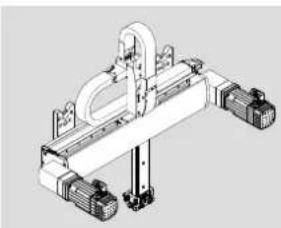
Linear gantry
natural_image
Isometric technical diagram of a mechanical assembly with no visible text or symbolsFESTO
Festo SE & Co. KG
Ruiter Straße 82
73734 Esslingen
Deutschland
+49 711 347-0
www.festo.com
Operating instructions
8170140
2022-03a
[8170142]
8170140
Translation of the original instructions
© 2022 all rights reserved to Festo SE & Co. KG
1 About this document
1.1 Applicable documents
i
All available documents for the product→ www.festo.com/sp.
i
The area of application and the approvals of the individual components of the kit are described in separate documents → www.festo.com/sp.
Download configuration-dependent documents
The technical data for the product are described in configuration-dependent documents.
These documents form part of the product documentation and can be downloaded as follows.
-
Read the order ID of the product.
-
Download the documents from the Festo Support Portal by entering the order ID → www.festo.com/sp.
-
Print out the documents and keep them together with these operating instructions.
2 Safety
2.1 General safety instructions
- Only use the product in its original condition without unauthorised modifications.
-Only use the product if it is in perfect technical condition.
- Observe labelling on the product.
—Before working on the product, switch off the power supply and secure it against being switched on again.
-Observe tightening torques. Unless otherwise specified, the tolerance is ± 20% .
2.2 Intended use
The intended use of the product is to execute positioning tasks within machines or automation systems with a higher-order controller in an industrial environment.
2.3 Foreseeable misuse
Never use the product as follows:
- With unauthorised modifications or alterations to the product
-With load limits exceeded
- In an invalid mounting position
3 Additional information
- Contact the regional Festo contact if you have technical problems
→ www.festo.com.
- Accessories and spare parts → www.festo.com/catalogue.
4 Product overview
| Linear gantry YZ module type | |
| YXML-1 EXCT-15 | |
| YXML-2 EXCT-30 | |
| YXML-3 EXCT-100 |
Tab. 1: Product allocation
Product labelling
In addition to product labelling of individual components, the product also has configuration-specific, higher-order product labelling in accordance with the following schematic:
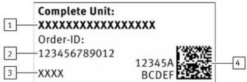
Fig. 1: Configuration-specific product labelling
1 Product name
2 Configuration-specific order ID
3 Festo serial number
4 Configuration-specific Product Key
The configuration-specific, higher-order product labelling is attached to all products at a specifically defined position.
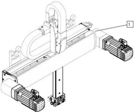
natural_image
Technical line drawing of a mechanical assembly with rollers and mounting brackets (no text or symbols)Fig. 2: Position of higher-order product labelling
1 Position of higher-order product labelling
5 Assembly
5.1 Demounting/mounting motors
DANGER
Serious injuries due to the motor falling from an elevated position.
- Demount motors with brake before assembling the product.
- Before loosening the retaining screws: secure the motor against falling.
WARNING
Electric shock.
- Make sure that the motors are disconnected from the power supply.
NOTICE
Third-party motors with a driving torque that is too high can damage the product.
- When using third-party motors observe the following:
- Only use motors with a brake.
• Maximum approved driving torque → www.festo.com/catalogue - Attachment dimensions motor interface → www.festo.com/catalogue
- Matching combination of coupling, coupling housing and motor flange
Motor attachment position, front
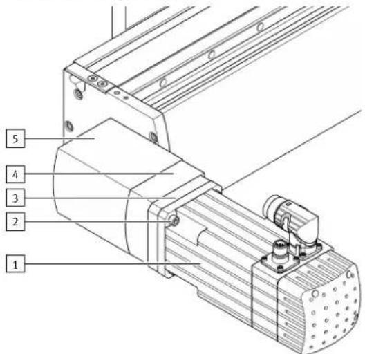
Fig. 3: EXCT-15-...-VV shown, motor as an example
Motor attachment position, rear
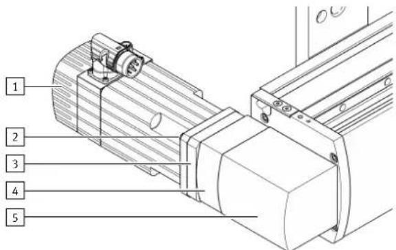
Fig. 4: EXCT-15-...-VH shown, motor as an example
1 Motor 1, left
4 Coupling housing
2 Retaining screw, 4x
5 Drive housing
3 Motor flange
Demounting
NOTICE
Product damage in the event of incorrect handling or falling down due to a change in the centre of gravity when the motors are demounted.
Fasten the product to the mounting surface.
Or
Place the product with the underside of the Y-axis on a stable surface,
e.g. mounting table:
- Do not subject the Z-axis to stress.
- Secure the product to the bases to prevent tipping or falling.
WARNING
Risk of injury from electric shock, impact, crushing.
With motors demounted the weight of the Z-axis may cause it to move uncontrolled in the Y-direction and Z-direction.
• Before demounting the motors:
- Secure the Z-axis to prevent uncontrolled movements.
- Bring the Z-axis interface to the bottom end position.
-
Disconnect all cables from the motor.
-
Unscrew the 4 retaining screws on the motor.
-
Remove the motor.
-
Repeat steps 1. ... 3. for the other motor.
Mounting
-
Position the motor flange and the motor.
-
Tighten the retaining screws.
Tightening torque EXCT-15 EXCT-30 EXCT-100
| Retaining screws [Nm] 6 18 18 |
-
Connect the cables to the motor.
-
Repeat steps 1, ... 3. for the other motor.
5.2 Adjust motor cable outlets
WARNING
Risk of injury from electric shock, impact, crushing.
After unscrewing the motor retaining screws, the Z-axis interface drops to the bottom end position.
- Make sure that the Z-axis interface is at the bottom end position.
The position of the motor cable outlets is factory-installed at the top mounting position. The position can be adjusted to the installation situation by rotating the motors in 90° steps.
Prerequisite: the product is secured to the mounting surface.
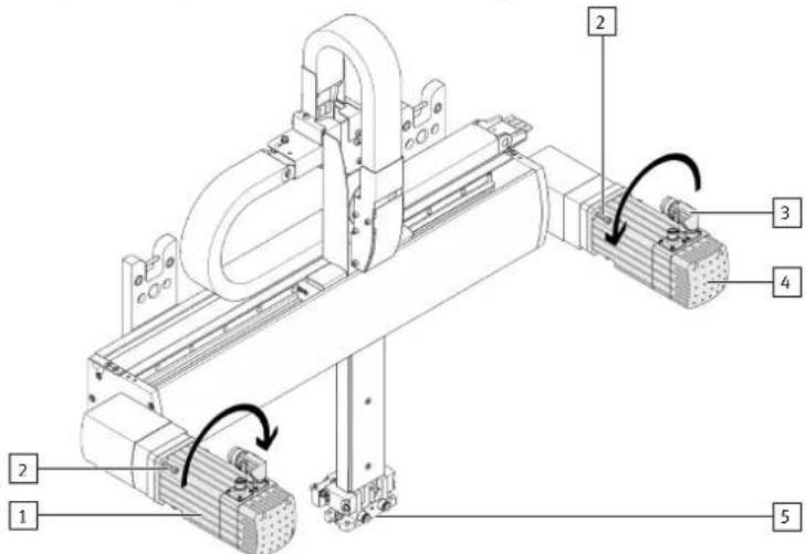
Fig. 5: EXCT-15 shown with front motor attachment positions
1 Motor 1, left
4 Motor 2, right
2 Retaining screw, 4x
5 Z-axis interface
3 Motor connection cable outlet
Procedure
i
Changing the cable outlets will result in loss of homing.
-
Position the Z-axis to ensure a range of movement of 10 cm in the Y-direction to left and right.
-
Disconnect the cables from the motor if they are connected.
-
Unscrew the retaining screws on the motor.
-
Rotate the motor in the installed state in the direction shown to the desired position:
- Motor 1, left: clockwise
-Motor 2, right: anticlockwise
i
For a rear motor attachment position:
The direction of rotation of the motors is identical with the directions shown
→ Fig. 5.
The Z-axis moves diagonally slightly upwards.
- Tighten the retaining screws.
Tightening torque EXCT-15 EXCT-30 EXCT-100
| Retaining screws [Nm] 6 18 18 |
- Connect the cables to the motor.
6 Technical data
i
Non-compliance with the technical data will damage the product.
The technical data are included in various documents:
- General technical data → www.festo.com/catalogue.
-Configuration-dependent technical data in the data sheet
→ www.festo.com/sp.