HMVY-1 - Ukategoriseret Festo - Gratis brugsanvisning og manual
Find enhedens vejledning gratis HMVY-1 Festo i PDF-format.

Brugerspørgsmål om HMVY-1 Festo
0 spørgsmål om dette apparat. Besvar dem du kender, eller stil dit eget.
Stil et nyt spørgsmål om dette apparat
Download vejledningen til din Ukategoriseret i PDF-format gratis! Find din vejledning HMVY-1 - Festo og tag din elektroniske enhed tilbage i hånden. På denne side er alle dokumenter nødvendige for brugen af din enhed offentliggjort. HMVY-1 af mærket Festo.
BRUGSANVISNING HMVY-1 Festo
- Verbindungsbausätze
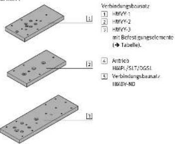
1.b. Montagebeispiel
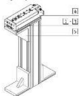
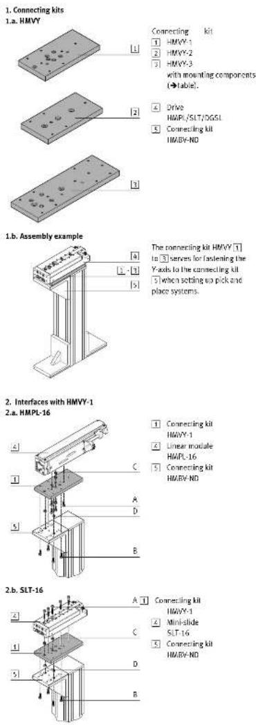
Bestimmungsgemäß dient der Verbindungsbausatz HMVY 1 bis 3 beim Aufbau von Pick & Place-Systemen zum Bofestigen der Y-Achsen 4 auf den Verbindungsbausatz 5.
- Schnittstellen beim HMVY-1
2.a. HMPL-16
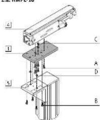
① Verbindungsbausatz
HMVY-1
Linearmodul
HMPL-16
5 Verbindungsbursatz
HMBV-ND
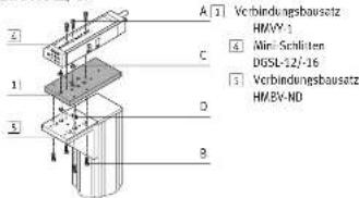
2.b. SLT-16
Verbindungsbausatz
HIVY-1
4 Mini-Schlitter
SLT-16
5 Verbindungsbausatz
HMBY-NO
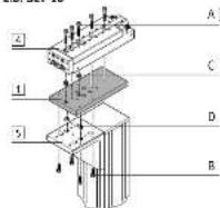
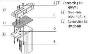
2.c. DGSL-12/-16
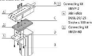
- Schnittstellen beim HMVY-2
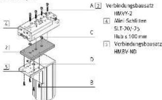
3.a.SLT-20/-25
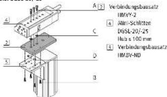
3.b. DGSL-20/-25
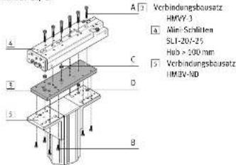
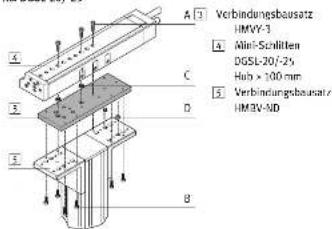
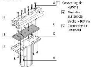
- Schnittstellen beim HMVY-3
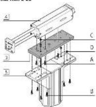
4.a.HMPL-20
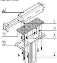
3 Verbindungsbausatz
HIVY-3
4 Linearmodul
HIMPL-20
3 Verbindungsbausatz
HMBV-ND
4.b. SLT-20/-25
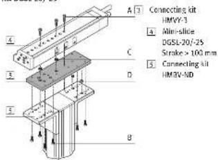
4.c.DGSL-20/-25
Montageanleitung (de)
712823/2007-01a
Verbindungsbausatz
HMVY-...
FESTO
Festo SE & Co. KG
Postreach
73726 LssIngen
149(0)212475
→ Hinweis
Der Bausatz HMVY... enthält alle maximal erforderlichen Befestigungs- elemente, zur Befestigung der jeweiligen Antriebseinheit 4 als Y-Achse am Verbindungsbausatz HMBV-NO 5.
→ Hinweis
- Beachen Sie
- dass nur die Befestigungskombinationen aus der Tabelle zu lässig
sind.
dass bei einigen Kombinationen Befestigungselemente übrig bleiben.
| Schnittstelle | 2.a. 4.b. 2.b. | 3.a. | 4.b. | 2.c. | 3.b. | 4.c. | |||||||||
| 1 Antrieb | HMPL- | SLT- | DGSL- | ||||||||||||
| Hub ≤ 100 mm | Hub > 100 mm | Hub ≤ 100 mm | Hub > 100 mm | ||||||||||||
| 16 20 | 16 20 25 | 20 25 | 12 16 20 | 15 20 25 | |||||||||||
| Bausatz | HMVY- | HMVY- | HMVY- | ||||||||||||
| 1 | 3 | 1 | 2 | 3 | 1 | 2 | 3 | ||||||||
| 2 Bausatz | HMBV-ND | HMBV-ND | HMBV-ND | ||||||||||||
| 1x 2x | 1x | 2x | 1x | 2x | |||||||||||
| M_w^2 [Nm] | |||||||||||||||
| A. Zylinderschrauben nach DIN 912 | |||||||||||||||
| Mx16 5,8 5x 5x | 3x^2 | ||||||||||||||
| Mx30 5x | |||||||||||||||
| Mx20 10 | 3x^2 | 3x | |||||||||||||
| Mx40 4x 6x | |||||||||||||||
| Mx45 4x 6x | |||||||||||||||
| B. Zylinderschrauben nach DIN 912 | |||||||||||||||
| Mx16 5,8 4x 4x 4x | 4x 8x 4x 4x 8x | ||||||||||||||
| C. Zentrierhülsen | |||||||||||||||
| ZDV-9-7 | 2x | ||||||||||||||
| ZBV-12-9 | 2x | 2x | |||||||||||||
| Z 8 | 2 | x | 2 | x | 2 | x | |||||||||
| ZTH-12 | 2x 2x | ||||||||||||||
| D. Zentrierhülsen | |||||||||||||||
| Z 8 | 9 | 2 | 2x8x | 2 | x | 2 | x 2x 2x | 2x | |||||||
1) M_p = Anziehdtrehmoment ; 2) Bei Mini-Schlitten DGSL mit Hub ≥ 50 mm sind nur? Schrauben erforderlich.
2.c. DGSL-12/-16
- Interfaces with HMYY-2
3.a.SLT-20/-25
![A[2] Connecting kit HMVY-2 A Mini-slide SLT-70:25 Stroke ≤ 100 mm B Connecting kit HMBV ND](/content/2026/05/1014938/images/254826434c015b960088d4a44c5907d980e5447efcd5de38552449f234f8ed32.jpg)
3.b. DGSL-20/-25
- Interfaces with HMYY-3
4.a. HMPL-20
3 Connecting kit
HMVY-3
4 Linear module
HMPL-20
Connecting kit
4.b.SLT-20/-25
4.c.DGSL-20/-25
Assembly instructions (en)
712823/2007-01a
Connecting kit
HMVY-...
FESTO
Festo SE & Co. KG
Posttrach
73726 LsIngen
49(0)21,247 www.essin.com
→ Note
Kit HMVY... includes all maximally required mounting components for attaching the respective drive unit 4 as a Y axis to connecting kit HMBV-ND 5.
→ Note
- Note: - that only attachment combinations shown in the table are permissible. - that mounting components may be left over with some combinations.
| Interface | 2.a. 4.b. 2.b. | 3.a. | 4.b. | 2.c. | 3.b. | 4.c. | |||||||||
| 4 Drive | HMPL- | SLT- | DGSL- | ||||||||||||
| Stroke < 100 mm | Stroke > 100 mm | Stroke < 100 mm | Stroke > 100 mm | ||||||||||||
| 16 20 | 16 20 25 | 20 25 | 12 | 16 20 | 15 20 25 | ||||||||||
| Kit | HMVY- | HMVY- | HMVY- | ||||||||||||
| 1 | 3 | 1 | 2 | 3 | 1 | 2 | 3 | ||||||||
| 5 Kit | HMBV-ND | HMBV-ND | HMBV-ND | ||||||||||||
| 1x 2x | 1x | 2x | 1x | 2x | |||||||||||
| M_w^2 [Nm] | |||||||||||||||
| A. Socket head screws as per DIN 912 | |||||||||||||||
| Mx16 5.8 5x 5x | 3x^2 | ||||||||||||||
| Mx30 5x | |||||||||||||||
| Mx20 10 | 3x^2 | 3x | |||||||||||||
| Mx40 4x 6x | |||||||||||||||
| Mx45 4x 6x | |||||||||||||||
| B. Socket head screws as per DIN 912 | |||||||||||||||
| Mx16 5.8 4x 4x 4x | 4x 8x 4x 4x 8x | ||||||||||||||
| C. Centring sleeves | |||||||||||||||
| ZDV-9-7 | 2x | ||||||||||||||
| ZDV-12-9 | 2x | 2x | |||||||||||||
| Z 8 + | 9 | 2 x | 2 x | 2 | x | ||||||||||
| ZDH-12 | 7x 7x | ||||||||||||||
| D Centring sleeves | |||||||||||||||
| Z 8 + | - | 9 | 2 2x8x | 2 x | 2 | x 2x 2x | 2x | ||||||||
1) M_p = Tightening torque. 2) On mini-slide DGSL with stroke ≤slant 50 mm only two screws are required.