EAPM-L2-SH - Ukategoriseret Festo - Gratis brugsanvisning og manual
Find enhedens vejledning gratis EAPM-L2-SH Festo i PDF-format.

Brugerspørgsmål om EAPM-L2-SH Festo
0 spørgsmål om dette apparat. Besvar dem du kender, eller stil dit eget.
Stil et nyt spørgsmål om dette apparat
Download vejledningen til din Ukategoriseret i PDF-format gratis! Find din vejledning EAPM-L2-SH - Festo og tag din elektroniske enhed tilbage i hånden. På denne side er alle dokumenter nødvendige for brugen af din enhed offentliggjort. EAPM-L2-SH af mærket Festo.
BRUGSANVISNING EAPM-L2-SH Festo
EAPM-L2-SH
Sensor bracket

Assembly instructions
8135693
2021-01a
[8135695]

Translation of the original instructions
© 2021 all rights reserved to Festo SE & Co. KG
1 Applicable documents
1
All available documents for the product → www.festo.com/sp.
| Document Product | |
| User documents | Actuator 3 ... 5 |
| Proximity switch | |
| Switch lug |
Tab. 1
2 Safety
2.1 Safety instructions
- Only mount the product on components that are in a condition to be safely operated.
- Observe tightening torques. Unless otherwise specified, the tolerance is ± 20% .
2.2 Intended use
2.2.1 Use
Mounting of a proximity switch for sensing the slide position on the basic profile of an actuator 3 ... 5
2.3 Training of qualified personnel
Work on the product may only be carried out by qualified personnel who can evaluate the work and detect dangers. Personnel must have the relevant mechanical training.
3 Additional information
- Accessories → www.festo.com/catalogue.
- Spare parts → www.festo.com/spareparts.
4 Product Range Overview
4.1 Scope of delivery

Fig. 1
4.2 Not in scope of delivery
Mini slide unit EGSS (1x)/spindle axis unit ELGS (1x)/electric cylinder unit EPCS (1x) or the following actuators:
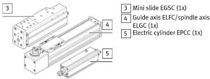
Fig. 2
5 Assembly
5.1 Attachment to mini slide
i
The sensor bracket 1 can also be mounted on the opposite side. However, in this case a switch lug cannot be mounted.
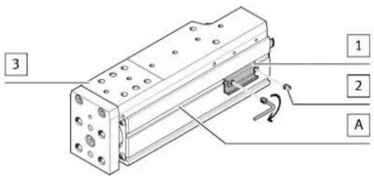
Fig. 3
- Position sensor bracket 1 in the slot [A] as shown.
– Tighten threaded pins 2. Tightening torque: 0.7 Nm
→ Sensor bracket 1 is jammed in the slot [A].
5.2 Attachment to guide/spindle axis
i
The sensor bracket 1 can also be mounted on the opposite side. A switch lug can be mounted on both sides.
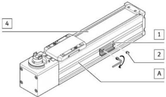
Fig. 4
- Position sensor bracket 1 in the slot [A] as shown.
- Tighten threaded pins 2. Tightening torque: 0.7 Nm
→ Sensor bracket 1 is jammed in the slot [A].
5.3 Attachment on electric cylinder
i
The sensor bracket 1 can be mounted on three sides. A switch lug cannot be mounted.
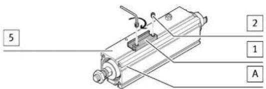
Fig. 5
- Position the sensor bracket 1 in the slot [A] so the sensor will later be in the middle of the profile.
- Tighten threaded pins 2. Tightening torque: 0.7 Nm
→ Sensor bracket 1 is jammed in the slot [A].