SYN 200TL-XH-US - Ukendt Growatt - Gratis brugsanvisning og manual
Find enhedens vejledning gratis SYN 200TL-XH-US Growatt i PDF-format.

Brugerspørgsmål om SYN 200TL-XH-US Growatt
0 spørgsmål om dette apparat. Besvar dem du kender, eller stil dit eget.
Stil et nyt spørgsmål om dette apparat
Download vejledningen til din Ukendt i PDF-format gratis! Find din vejledning SYN 200TL-XH-US - Growatt og tag din elektroniske enhed tilbage i hånden. På denne side er alle dokumenter nødvendige for brugen af din enhed offentliggjort. SYN 200TL-XH-US af mærket Growatt.
BRUGSANVISNING SYN 200TL-XH-US Growatt
Overview
SYN 200-XH-US Quick Guide
| 1 | 3 | 2 | 5 | 4 | 6 | 6 | 7 | 8 | 9 |
| 10 | 11 | 12 | 13 | ||||||
| 1: Front panel | 2: Grid indicator | 3: Communication indicator | 4: Status Indicator | ||||||
| 5: Fault indicator | 6: Inverter wiring port | 7: Load wiring port | 8: Grid wiring port | ||||||
| 8: Hast sink | 10: COM wiring port | 11: Reserved wiring port | 12: Generator wiring port | ||||||
Installation
| 2.1 System overview | 2.2 Installation requirements | |||||
| SVM 207-XH-US | ≤15" | 300mm | W | |||
| Source | ||||||
| PV | ≥200mm | ≥100mm | ≥800mm | |||
| Cost | = | |||||
| Battery | ≤200mm | |||||
| Positive communication unit | Generator | Local Fuel | Dimensions | W(mm) | Height (m) | G(mm) |
| SVM 206-H14-J5 642 5/12.52 | 856 524 N Y 182 8V 12 | |||||
2.4 Required tools
| No. | Name | Size | No. | Name | Size | |||||
| 1 | Elastic drill | 0 × 1 mm | 2 | wrench | 0 × 10 mm | |||||
| 3 | Allen wrench | 0 × 5 \& 8 mm | 4 | Cross rise | 0 × 5 mm | |||||
| 1 2 3 6 | 4 | 5 | 7 | 8 | 5 | From flat | 0 × 1 mm | 6 | Wire cutter | / |
| 7 | Wire stripper | / | 8 | hammer | / |
Electrical connection
3.1 Electrical connection
| A | Invertercommunication port | B | Generator controlport | C | Inverter wiring port | E | |
| D | Inverter GroundTerminals | E | Inverter NeutralTerminals | F | Generator wiring port | H | |
| G | Grid switch | H | Grid wiring port | I | Load Panel wiringprot | J | |
| J | Main NeutralTerminals | K | Main GroundTerminals | K |
Cables prepared by the customer:
| Use | Type | Size | Note: | |
| 1 | Grounding Conductors (Load/Generator/Inverters) | Yellow-green (ecketed or solid zinc copper | 7~12 AWG (Load/Generator)8~6 AWG (Inverters) | It is recommended to use two or three polychromatic multi-core copper cables cables for Grid/Load/ Generator/ Inverter connection. |
| 2 | AC output conductors (Load/Grid) | 0~4/5AWG | Recommended using yellow-green single multi-core cables for PE connection. | |
| 3 | Generator Input conductors | Multi-color jacket, copper | 4~0 AWG | Recommended using shielded twisted pair cable for RS485 connection. |
| 4 | Inverter Input conductors | 6~5 AWG | ||
| 5 | 12V power output conductors | Red and black multi-color copper | 16~14 AWG | |
| 6 | Communication cable | CAT5E suggested | / |
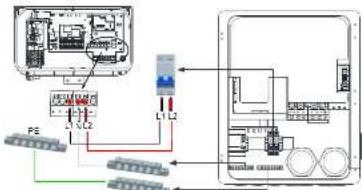
3.2 Connecting the SYN 200-XH-US to the Grid panel.
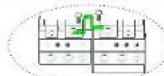
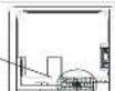
| 1. Release the Allen screws of the upper cover and open the upper cover.2. Install a conduit of the required diameter into the Grid conduit entry. Use the conduit holder to support the conduit.3. For versions with circuit breaker. Pull down the main breaker until it shows OFF.Ensure that the main breaker is OFF, as shown in Figure 1.4. Pass the cable from the grid through the grid conduit to the terminals of the circuit breaker. Tighten the terminal screws with a torque of 230 in"fbs / 26N·m, as shown in Figure 2.5. For version without circuit breaker. Pass the cable from the grid through the grid conduit to the GridL1 and GridL2 terminals of the SYN 200-XH-US. Tighten the terminal screws with a torque of 221in"fbs / 25N·m, as shown in Figure 3.6. Connect the neutral and grounding wires to the neutral and grounding terminals.Tighten the terminal screws with a torque of 221in"fbs / 26N·m. | ONOFF |
| 2 | 3 | |||
| GND | ||||
| GND | ||||
| GND LT GND LT2 | LL LT2 NTE | |||
| DTLENTPE | ||||
| (1, 12) | ||||
| N | ||||
| PF |
3.3 Connecting the SYN 200-XH-US to the Load panel.
| 1. Install a conduit of the required diameter into the Loads conduit entry. Use the conduit holder to support the conduit.2. Pass the cable from the AC Loads panel through the Loads conduit to the Load_L1 and Load_L2 terminals of the SYN 200-XH-US. Tighten the terminal screws with a torque of 221in3bs / 25N3ms.3. Connect the neutral and grounding ulters to the neutral and grounding terminals. Tighten the terminal screws with a torque of 221in3bs / 25N3ms, as shown on the right. | AC Loads Panel |
| Lod_L1 load_12 LON PC | |
| PE |
3.4 Connecting the SYN 200-XH-US to the Inverter
3.4.1 Inverter communication cables installation
- Install a conduit of the required diameter into the COM conduit
entry. Use the conduit holder to support the conduit.
- Pass the shielded communication cable through the COM
conduit. One end of the communication cable is connected to the 6-pin connector CN8 of the SYN 200-XH-US, and the other end is connected to the 3-pin connector CN24 of the MIN TL-XH-US inverter.
You must install the communication cable with the MIN TL-XH-US inverter, otherwise the system will not work normally.
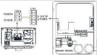
Communication connection between SYN 200-XH-US and Inverter
3.4.2 Installation inverter AC power cables
-
Install a conduit of the required diameter into the INV conduit entry. Use the conduit holder to support the conduit.
-
Pass the cable through the INV conduit
-
Connect the neutral and grounding cables to the corresponding neutral and grounding terminals. Tighten the terminal screws with a
lorsque of 13.2 in'bs / 1.5 N'm. 4 Correct the QFID-1 and QFID-2 terminal (the MINT) XUUS invested in the WIFexchension of OYN-200 XUUS. Turkey has
- Connect the GRID L1 and GRID L2 terminal of the MIN 1L-XH-US Inverter to the INV Breaker terminal of SYN 200-XH-US. Tighten the terminal screws with a torque of 13.2 in'bs / 1.5 N·m.
Power cable connection between SYN 200-XH-US and inverter
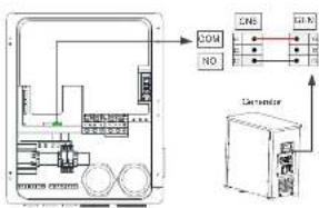
3.5 Connecting the SYN 200-XH-US to Generator
You must install the communication cable with the Generator first, and then install the power cables.
3.5.1 Generator communication cables installation
- Pass the shielded communication wire through the COM conduit. One end of the communication cable is connected to the 2-pin connector of SYN 200-XH-US, and the other end is connected to the remote control port of the generator.
flowchart
graph TD
    A["Device"] -->|COM| B["Sensor"]
    A -->|NO| C["Sensor"]
    A --> D["Sensor"]
    B --> E["Signal Lines"]
    C --> F["Signal Lines"]
    D --> G["Signal Lines"]
Communication connection between SYN 200 3H US and Generator
Note: The COM/NO signal of CNG is the remote control switch signal of the generator.
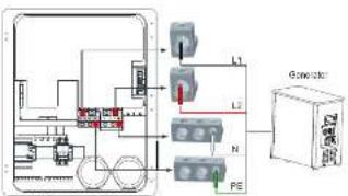
3.5.2 Generator input power cable installation
- Install a conduit of the required diameter into the generator conduit entry. Use the conduit holder to support the conduit.
- Pass the cable through the generator conduit.
- Connect the ground cable to the ground terminal. Tighten the terminal screws with a torque of 141 in'lbs./16 N'm.
- Connect the L1 and L2 terminal of the generator to the GEN L1 and GEN L2 terminal of SYN 203-XH-US. Tighten the terminal screws with a torque of 141 in'lbs./16 N'm.
flowchart
graph TD
    A["Device 1"] --> B["L1"]
    A --> C["L2"]
    A --> D["N"]
    A --> E["PE"]
    F["Console Box"] --> G["Control Unit"]
    style A fill:#f9f,stroke:#333
    style F fill:#ccf,stroke:#333
    style G fill:#cfc,stroke:#333
Connection to the Generator
4.LED Indication
| Description | LFD color | LFD status | SYN 200-XH-US status | |
| Grid indicator | Green | Solid | Connect to the grid | |
| Communication indicator | Green | Solid | Communication with the inverter is normal | |
| Status indicator | Green | Solid | On-grid works normally | |
| 1S on and 1S off | Off-grid works normally | |||
| 3S on and 3S off | The generator works normally | |||
| Fault Indicator | Red | Solid | Fault | |
| 1S on and 1S off | Overload |
Note: If the four indicator lights flash at the same time, it means that the SYN 200-XH-US is upgrading the firmware.
5. System startup and shutdown operations
5.1 System power-on operation, please follow the steps below:
- Close the DC switch of the ARO battery. Then close the DC switch of the inverter. The battery cannot be weaken up if there is no PV input, you move press and hold the battery switch until the indicator light refrubs. Please refer to the ARO battery installation manual as it does not have a 200-pin input circuit breaker. This is also shown for Figure 1. 2. Push the grid input circuit breaker to the "ON" position, indicating that the grid input breaker is closed, as shown in Figure 2. (For versions with circuit breakers): 4. Download our APP end set the inverter off-grid output through the APP. For details, please refer to the ARO battery's function. 5. If the grid indicator, communication indicator, and status indicator of the SYN 200-XH-US are all green and the fault indicator is off. It means that, the SYN 200-XH-US is working normally, System indicator, please refer to Section 4. 6. Reading steps fail to grow on the device, check the operation methods carefully or contact us.
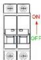
Figure 1
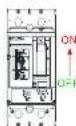
Figure 2
5.2 System power-off operation, Please follow the steps below:
- Disconnect the miniature circuit INV breaker on the SYN 200-XH-US.
- Disconnect the UG switch of the inverter Press and holds the battery switch button until the indicator light goes out. Then turn off the UG switch of the ARO battery. Please refer to the ARO battery installation manual.
- Pull down the Grid breaker switch until the word OFF is displayed, indicating that the circuit breaker is off.
- Wait and observe that the inverter, battery, SYN 200-XH-US and other indicators are all off, indicating that the system is completely powered off.
6. Manual bypass operation
In case of the SYN 200-XH-US is failure, it cannot be switched to the bypass state. In order to ensure household electricity, you can manually switch to the mains bypass state by performing the following operations.
- Shutdown the entire system please refer to section 5.2.
- Insert the 3-pin terminal with the short wire into the 3-pin interface of the SYN 200-XH-US as shown in the right figure1.
-
Make sure that the AC circuit breaker of the grid is disconnected, and manually rotate the white switch counterclockwise to the "ON" position, as shown in the right figure2.
-
Power up the entire system, please refer to section 5.1.
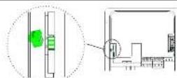
Figure1
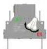
Figure2

Note: Where Electrical Inspection Authorities require the neutral assembly to be disconnected from the enclosure, we need to remove the bonding jumper shown in the picture on the right.

7. Service and contact
Goeyou USA Inc
9227 Reseda Blvd.#135 Northridge,CA #1324,USA.
T. +\$18,900-9177
E. usarvico@qiriyurdo.com
W. www.rosaia-suretica.com
- Writing on all and the town

Marus
GR UM 252 A-00


Growatt New Energy