MIN 2500-4600TL-XH - Inverter Growatt - Gratis brugsanvisning og manual
Find enhedens vejledning gratis MIN 2500-4600TL-XH Growatt i PDF-format.

Brugerspørgsmål om MIN 2500-4600TL-XH Growatt
0 spørgsmål om dette apparat. Besvar dem du kender, eller stil dit eget.
Stil et nyt spørgsmål om dette apparat
Download vejledningen til din Inverter i PDF-format gratis! Find din vejledning MIN 2500-4600TL-XH - Growatt og tag din elektroniske enhed tilbage i hånden. På denne side er alle dokumenter nødvendige for brugen af din enhed offentliggjort. MIN 2500-4600TL-XH af mærket Growatt.
BRUGSANVISNING MIN 2500-4600TL-XH Growatt

ROWATT
MIN 2500-6000 TL-XH Quick Guide

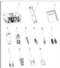
Overview
natural_image
Collection of laboratory glassware and equipment components (no visible text or labels)| Object | Description | Quantity |
| A | Inverter | 1 |
| B | Mounting bracket | 1 |
| C | Quick Grains | 1 |
| D | Monitor(Optional) | 1 |
| E | Signal connector | 2 |
| F | Self-tapping screws | 3 |
| G | Safety-lock screw | 1 |
| H | Plastic expansion pipe | 3 |
| I | PV+PV- terminal | 2/2 |
| J | PV+PV- and BAT+BAT terminal | 3/3 |
| K | AC connector | 1 |
| L | Uninstall signal or AC connector tool | 1 |
| M | Uninstall PV or BAT terminal tool | 1 |

Installing the Device

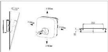
allation Requirements
Tilt and Space
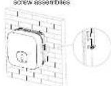
2.3 Installing the Monitor
Ensure that the Monitor is installed securely.
2.2 Installing the Mounting Bracket And Min 2500-6000 TL-XH
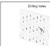
Fix the wall bracket
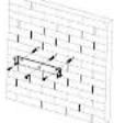
Installation & Tighten

Connecting Cables

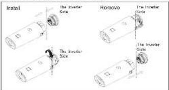
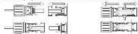
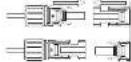
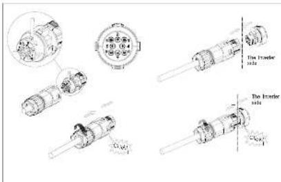
alling the PV Input Power Cable
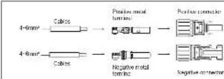
Pull the PV input power cable back to ensure that it is connected security.
The inner Side

The Interior Side
3.2 Installing the BAT Input Power Cable
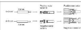
Pull the BAT input power cable back to ensure that it is connected securely.
The Investor Side

The Investor Side
3.3 installing the AC Output Power Cable
Connect the AC output power cable to the AC connector
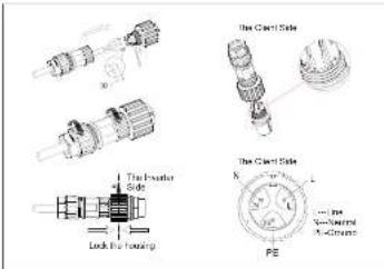
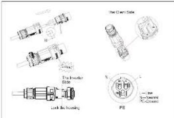

Notice: On the right is the Australian special AC connector.
Suggest using 6mm2 cables Ensure the exposed core wire is totally inserted into the cable hole and connected securely.
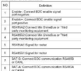
3.4 Installing the SYS COM Signal Cable
SYS COM Part Pin Definitions
3.5 Installing the COM Signal Cable
We use 6Pin COM Port Connector as Power Control Interface(PCI) for European models or Connector as inverter DRED connection(DRM) for Australia.
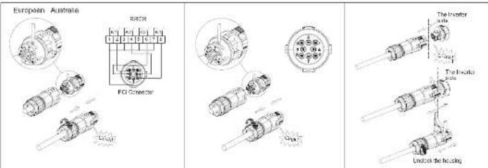
COM Port Pin Definitions- Power Control Interface(PCI)
| NO | 1 2 3 | 4 | 5 | 6 | 7 | 8 | ||
| Function | +12V | GND | Relay contact 1 input | Relay contact 2 input | Relay contact 3 input | Relay contact 4 input | GND | Not connected |
| Connect to RPCR | Not connected | K1 - output | K2 - output K3 - output | K4 - output | Relays common node | Not connected | ||
COM Port Pin Definitions- DRED connection
| NO | 4 | 5 | 6 | 7 | 6123 | |||
| Function | -12V | DRM1/5 DRM2/6GND | DRMS7 DRM4/8 REFGEN | COM/DRM0 | ||||

-
When laying out signal cables, separate them from power cables to avoid strong signal interference sources.
-
Do not confuse the connector to the COM port and the connector to the SYS COM port.
-
The COM port Aonly provides a functional port-PCI or DRM.
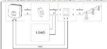
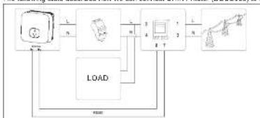
4. Connecting Meter
The following table describes how we can connect EASTRON meter (SDM230-Modbus) to inverter.
flowchart
graph TD
    A["Input"] --> B["Process"]
    B --> C["Output"]
    C --> D["Load"]
    D --> A
    style A fill:#f9f,stroke:#333
    style B fill:#ccf,stroke:#333
    style C fill:#cfc,stroke:#333
    style D fill:#fcc,stroke:#333
| Meter Pin NO. | Description | Connect to Inverter |
| 1 | L-in | / |
| 2 | L-out | AC connector & Load L |
| 3 | N-in | / |
| 4 | N-out | AC connector & Load N |
| 5 | RS469A | SYS COM Pin 5 RS469A1 |
| 6 | RS469B | SYS COM Pin d RS469B1 |
The following table describes how we can connect CHINT meter (DDSU636) to inverter:
flowchart
graph TD
    A["Input"] --> B["Load"]
    B --> C["Control Unit"]
    C --> D["Output"]
    D --> A
    style A fill:#f9f,stroke:#333
    style B fill:#ccf,stroke:#333
    style C fill:#cfc,stroke:#333
    style D fill:#fcc,stroke:#333
| Meter Pin NO. | Description | Connect to Inverter |
| 1 | L-in | / |
| 2 | L-out | AC connector & Load L |
| 3 | N-in | / |
| 4 | N-out | AC connector & Load N |
| 7 | RS489A | SYS COM Pin 5 RS485A1 |
| 8 | RS485B | SYS COM Pin 6 RS485B1 |
5. Verifying the Installation
1.The Min 2500-6000TL-XH is installed correctly and securely.
2. The Monitor is installed correctly and securely
3. The ground cable is connected correctly and securely.
4. The DC switch and all the switches connecting to the MN 2001-DC/TE-XH are OFF.
5. The AC output squareable, PV&PAT input squareable and signal cable are annotated separately and uniquely
6. Unused terminals and ports are locked by waterlight caps.
6. Button touch operation
| Touch button | Description | |
| Single touch | Switch display or Number +1 | |
| Double touch | Enter | |
| Thine touch | Previous menu | |
| Hold 5s | Confirm country selling or Number recover default value |
7. Powering On the System
Step1: Turn on the DC switch at the bottom of the Min 2500-6000TL-XH. Step2: Turn on the AC switch between the Min 2500-8000TL-XH and the power grid. Step3: When the OLED show "Country/Area VDE0126", Please Set the country follow the below step4.

When the OLED show "Country/Area Australia", Please Set the country follow the steps

Step4: Single touch to switch Country, such as N4105. Then jump to step8.

Step5: Single touch to switch Country, such as Newzealand.

Step6: Press the touch key for 5s or No operation on the OLED for more than 30S (The country of the current interface is selected by default)the OLED shows Country setting is complete.

Tips
If the LED light is green, the system is operating normally. You can react the country by "Sat Country" in the submenu of "Sat parameter".
Shenzhen Growatt New Energy Co., Ltd
4.13F, Building A, Siro German (Europe) Industrial Park,
Hangzheng (Wangshan Bank), Shenzhen, China
1 +86 2753 274) -942
E service@inkenter.com
W. WWW.girder.com

Download Manual

GR-UM-102-A-02