Oryx - Ukategoriseret FLIR - Gratis brugsanvisning og manual
Find enhedens vejledning gratis Oryx FLIR i PDF-format.

Brugerspørgsmål om Oryx FLIR
0 spørgsmål om dette apparat. Besvar dem du kender, eller stil dit eget.
Stil et nyt spørgsmål om dette apparat
Download vejledningen til din Ukategoriseret i PDF-format gratis! Find din vejledning Oryx - FLIR og tag din elektroniske enhed tilbage i hånden. På denne side er alle dokumenter nødvendige for brugen af din enhed offentliggjort. Oryx af mærket FLIR.
BRUGSANVISNING Oryx FLIR
ORYX®
GigE Vision
Will your system support the camera?
Recommended System Configuration:
■ OS—Windows or Linux (32- or 64-bit)
■ CPU—Intel i7 or greater
■ RAM—8 GB dual channel
■ Ports—10GBASE-T network adapter
■ Software—Microsoft Visual Studio 2010, Visual Studio 2013, or Visual 2015 (to run and compile example code)
Do you have a downloads account?
A downloads account is required to download software and firmware.
- Go to www.flir.com/account.
- Enter your email address and click Continue.
- Complete the Create an account form and click Continue.
- You will receive an email with a link to activate your account.
- Once activated, you can login using the credentials you've created.
The Oryx resources page has many resources to help you operate your effectively, including:
■ Spinnaker ^® SDK software, including drivers (login required)
■ Firmware updates and release notes (login required)
■ Dimensional drawings and CAD models
■ Documentation
Do you have all the parts you need?
To install your camera you need the following components:
- Ethernet cable
■ GPIO cable
Lens
■ Tripod adapter (optional)
■ Interface card
Teledyne FLIR sells a number of the additional parts required for install purchase, visit the Accessories page.
Camera Care
To clean the imaging surface of your camera, follow the steps outlined the imaging surface of your camera.
Extended exposure to bright sunlight, rain, dusty environments, etc. may problems with the electronics and optics of the system.
Avoid excessive shaking, dropping, or mishandling of the device.
Warning! Avoid electrostatic charging.
Installing Your Interface Card and Software
- Install your Interface Card
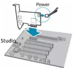
Ensure the card is installed per the manufacturer's instructions.
Connect the internal IDE or SATA power connector on the card to the computer supply.
Alternatively, use your PC's built-in host controller, if equipped.
Open the Windows Device Manager. Ensure the card is properly install cards appear under Network Adapters. An exclamation point (!) next to indicates the driver has not yet been installed.
- Install the Spinnaker® Software
Note: For existing users who already have Spinnaker installed, we ensuring you have the latest version for optimal performance of you do not need to install Spinnaker, use SpinView to install an for your card.
a. Go to the Spinnaker SDK page.
b. Click the Download button. You are prompted to login, if not already
c. Select your operating system. Depending on your selection there may versions to select.
d. After download is complete, open the file to start the Spinnaker
e. Follow the steps in each setup dialog.
3. Enable jumbo frames on the Ethernet card
a. In Start->All Programs-> Spinnaker SDK->SpinView, right click on the Adapter and select Adapter Configuration, then select IP Configuration
b. Click Open Network Connections.
c. Click Change Settings.
d. Click on the Advanced tab and from the Settings list select Jumbi
e. Set the Value to 9014 Bytes and click OK.
See How to Optimize GigE Network Adapter Settings for more information on configuring for best performance.
Using the Spinnaker SDK ^m Cleaning
You can monitor or control features of the camera through Spinnaker provided in the Spinnaker SDK, or through the SpinView camera evaluation application. A Programmer's Guide and API Reference is included in the
Installing Your Oryx 10GigE
- Attach a Lens
Unscrew the dust cap from the lens holder to install a lens.
- Connect the interface Card and Cable to the Camera
Plug the interface cable into the host controller card and the camera. The cable jack screws can be used for a secure connection.
When the camera is first connected, the operating system automatically installs the camera driver. Camera drivers are available with the Spinnaker SDK installation.
- Plug in the GPIO connector
GPIO is used for power, trigger, serial input output, and strobe.
- Confirm Successful Installation
Run the SpinView application: Start->All Programs-> Spinnaker->SpinView
The SpinView application can be used to test the camera's image acquisition capabilities.
- Configure IP Settings if necessary
By default, a dynamic IP address is assigned to the camera according to DHCP protocol. If DHCP addressing fails, a link-local address is assigned necessary, in SpinView change the IP address of the camera to be on the subnet as the NIC.
Changes to your camera's installation configuration can be made using the SpinView application.
Status Indicator LED
LED 10GigE
| No Light | No poweror LED is in inactive stateor LED is in error status state with no error |
| Blinking Green (1 blink) | Link-Local Address (LLA) |
| Blinking Green (2 blinks) | DHCP IP Address |
| Blinking Green (3 blinks) | Persistent IP Address |
| Solid Green | Acquisition Started |
| Rapid Flashing Green | Firmware update in progress |
| Flashing Green and Red | General Error |
Network Status LEDs
| No Light | No network connection |
| Left and Right Bright Green | 10 GigE connection |
| Left Dim and Right Bright Green | 1 GigE connection |
| Left and/or Right Blinking Green | Data transfer in progress |
Camera Interface
Ethernet Connector
The 8-pin RJ-45 Ethernet jack is equipped with two (2) M2 screwholes connection. Pin assignments conform to the Ethernet standard.
General Purpose I/O Connector
The camera is equipped with a 12-pin GPIO connector on the back
Small, Standard, and Large Case Models
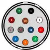
Color Pin Line Function Description
| Black | 1 | N/A | GND | DC camera power ground |
| White | 2 | N/A | POWER | DC camera power |
| Red | 3 | Line 1 | GPIO_OPT_OUT1 | Opto-Isolated output (GPO1) |
| Green with black stripes | 4 | Line 4 | GPIO_OPT_OUT2 | Opto-Isolated output (GPO2) |
| Orange | 5 | Line 0 | GPIO_OPT_IN1 | Opto-Isolated Input (GPI1) |
| Blue the White with black stripes | 6 | Line 3 | GPIO_OPT_IN2 | Opto-Isolated Input (GPI2) |
| 7 | Line 2 | GPIO_TTL_IO3 | TTL Input/output 3* | |
| Red with black stripes | 8 | Line 5 | GPIO_TTL_IO4 | TTL input/output 4* |
| Green with black stripes | 9 | N/A | GND | DC camera power ground |
| Orange with black stripes | 10 | N/A | POWER | DC camera power |
| Blue with black stripes | 11 | Line 6 | 3.3 V OUTPUT | +3.3 V output, current 120 mA (nominal) - firmware enabled |
| Black with white stripes | 12 | N/A | OPTO_GND | Ground for opto-isolated I/O, not connected to camera ground |
For More Information
Teledyne FLIR endeavors to provide the highest level of technical support possible to you.
Support resources can be accessed through the Oryx resources page.
| Your camera's settings and capabilities—Technical Reference or Camera Reference |
| Spinnaker ^® SDK—API Reference / Programmer's Guide |
| Selecting a lens for your camera |
| 10GigE Best Practices: Setting Up a Single-camera System |
| Using third-party applications from our software partners |
Contacting Us
For any questions, concerns or comments please contact us via the methods:
for secure
| General questions | |
| Support Ticket | Technical support |
| Website | Find specifications, support articles, downloads on the product page at Teledyne FLIR machine vision |
11/29/2022
Names and marks appearing on the products herein are either
registered trademarks or trademarks of FLIR Systems, Inc. and/or its subsidiaries.
© 2015-2022 FLIR Integrated Imaging Solutions Inc. All rights reserved.

TELEDYNE FLIR
Everywhereyoulook™