M332 - Overvågningskamera FLIR - Gratis brugsanvisning og manual
Find enhedens vejledning gratis M332 FLIR i PDF-format.

Brugerspørgsmål om M332 FLIR
0 spørgsmål om dette apparat. Besvar dem du kender, eller stil dit eget.
Stil et nyt spørgsmål om dette apparat
Download vejledningen til din Overvågningskamera i PDF-format gratis! Find din vejledning M332 - FLIR og tag din elektroniske enhed tilbage i hånden. På denne side er alle dokumenter nødvendige for brugen af din enhed offentliggjort. M332 af mærket FLIR.
BRUGSANVISNING M332 FLIR
FLIR®
M300 SERIES
INSTALLATION & OPERATION INSTRUCTIONS
English (en-US) | Date: 10-2019 | Document number: 71004-2
© 2019 FLIR Systems, Inc.
natural_image
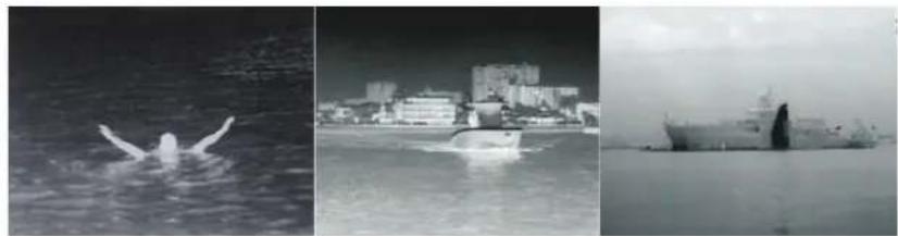
Three black-and-white photos: a person swimming in water, a city skyline with buildings, and a naval vessel on calm water (no visible text or symbols)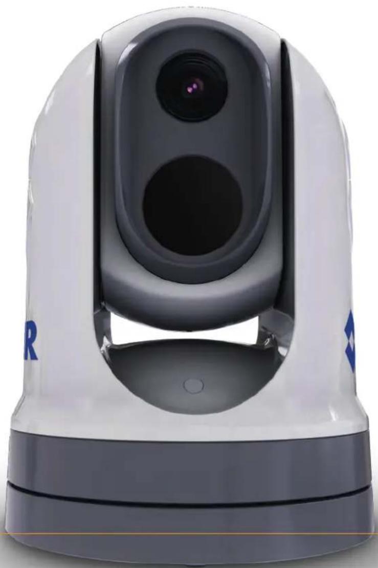
natural_image
White and gray remote camera with dual lens and control panel (no visible text or symbols)T rademarkandpatentsnotice
RaymarineT ackticCleaPulseT ruzoomSeaT allSeaTalk registeredorclaimedtrademarksofRaymarineBelgium.
hs SeaTalkngan Micronetare
FLIR, lightHouseDownVisionSideVisionRealVisionHyperVisionDragonflyElement, QuantumAxiomInstalertInfrareEverywhereTheWorld'SixtSensenClearCruisere registeredorclaimedtrademarksofFLIRSystems, Inc.
Allothertrademarks, tradenames, or company names referenced herein are used for identification only and are the property of their respective owners.
Thisproductisprotectedbypatents,designpatents,patentspending,ordesignpatentspending.
Patentsnotice
ThisproductiscoveredbyoneormoreofUSPatentNos:7470904;7034301;6812465;7470902;6929410andotherpatentspending,ordesignpatentspending.
FairUseStatement
Y oumayprintnomorethanthreecopiesofthismanualforyourownuse.Youmaynotmakeany furthercopiesordistributeorusethemanualinanyotherwayincludingwithoutlimitationexploiting themanualcommerciallyorgivingorsellingcopiestothirdparties.
Exportcontrol
M300SeriesthermalcamerasarecontrolledbyUSexportlaws.
Therearespecialversionsofthesystemthatareapprovedforinternationaldistributionandtravel. PleasecontactFLIRcustomersupportifyouhaveanyquestions.
ContactdetailscanbefoundontheFLIRwebsite, www.flir.com.
ExportAdministrationRegulations(EAR)
ThisdocumentiscontrolledtoFLIRTtechnologyLevel1.Theinformationcontainedinthisdocument pertainstoadualuseproductcontrolledforexportbytheExportAdministrationRegulations(EAR). FLIRtradesecretscontainedhereinaresubjecttodisclosuresestrictionsasamatteroflaw.Diversion contrarytoUSlawisprohibited.USDepartmentofCommerceauthorizationisnotrequiredpriorto exportortransfertoforeignpersonsorpartiesunlesssotherwiseprohibited.
Softwareupdates
Important: ChecktheFLIRwebsiteforthelatestsoftwarereleasesforyourproduct.
www.flir.com/marine/support
Producthandbooks
ThelatestversionsofallEnglishandtranslatedhandbooksareavailabletodownloadinPDF formatfromwww.flir.com/marine/support. Pleasecheckthewebsitetoensureyouhavethelatesthandbooks.
Copyright©2019FLIRSystems,Inc.Allrightsreserved.
Contents
Chapter1 Importantinformation....9
Cleaningthecamera....10
Inspectingthethermalcamera....11
Watingress....11
Disclaimer....11
EMCinstallationguidelines....11
Suppressioferrites....12
Connectionstootherequipment....12
DeclarationofConformity....12
Produ/disposal....12
Warranty registration....13
IMOandSOLAS....13
Technical accuracy....13
Chapter2Documentandproductinformation....15
2.1 Documentinformation....16
Applicableproducts....16
Additionalsystemcomponents....17
Produ documentation....17
2.2Systemoverview....17
2.3Productoverview....18
M30(singlepayload)....18
M30(duapayload)....20
2.4Partssupplied....21
M300-Seriesamera....21
Partssupplied—JCU-2(availableseparately)....22
2.5Compatible joystickcontrollers(JCU)....23
2.6Compatible multifunction displays....23
Multifunctiondisplaysoftwarerequirements....23
Chapter3Installation....25
3.1 Generallocationrequirements....26
Compassafdistance....27
- Tool required....27
3.3Productdimensions....28
M30Series....28
M300Serieswithoptionalmountingriser....29
JCU-2(availableseparately)....30
3.4Cameraorientation....31
3.5 Camer amounting....31
Locationrequirements....31
Mountingheamera....32
Mountingthecamerawiththeoptionalmountingriser....34
3.6JCU-2Mounting....37
Locationrequirements....37
Removingthekeypadmat....38
Flushmountingthekeypad....38
Surfacemountingthekeypad....40
Fitting the keypad....41
Chapter4Connections......43
4.1 Generalcablingguidance....44
Cable type and length....44
Cableouting....44
Strairelief....44
Circuitsolation....44
Cableshielding....45
HD-SDIcableconnection....45
4.2Connectionsoverview....45
Connectingables....46
Orientationofright-angledconnectors....47
4.3Videoconnections....47
Videoandnetworkcables....49
4.4NMEA0183connection....49
4.5T yricalsystems....51
4.6Networkconnections....51
Non-RayNetsystems....52
RayNetsystemswithRaymarineLightHouse3multifunctiondisplays(MFDs)....56
4.7Powerconnection....59
Powedistribution....60
In-linefuseandthermalbreakerratings....63
Grounding—Dedicateddrainwire....63
Chapter5Cameracontroloptionsandstatusicons....65
5.1 Camera control options....66
5.2Cameraimage....66
ThermaCamera....66
Camerstatuscons....67
Imagedjustments....71
5.3Cameracontrol....73
Partjandoom....73
Homposition....73
Surveillancenode....74
Chapter IV Interface operation....75
6.1Webbrowseruserinterfaceoverview....76
6.2Settingupanetworkconnectiontothecamera....76
6.3 Logging into the Web browser user interface....77
FirstmLogin....78
- Widefeed....78
6.5 Camerasettingsmenus....79
6.6Systemsettings....79
6.7 roubleshoot....80
SettingastaticIPaddress....80
Chapter7JCU-2operation....81
7.1MainMenu....82
7.2JCU-2controlsoverview....82
ConfiguringJCU-2user-programmablebuttons(UPBs)....84
Chapter8MFDoperation....87
8.Overview....88
8.2ClearCruisethermalanalytics....88
- Auto-tracking....89
Chapter9Maintenance....91
9.1 Service and maintenance....92
9.2Cleaningthecamera....92
Chapter10Systemchecksandtroubleshooting....93
10.1 Thermal cameratroubleshooting....94
10.2FLIRMaritimeproductsupportandservicing....95
Chapter11T echnicalspecification....97
11.1M300Seriescameras....98
Technical specification....98
Videspecification....98
11.2CU-2....99
Technical specification....99
Chapter12Sparesandaccessories....101
12.1M300Seriescamerasparesandaccessories....102
12.2FLIRnetworkingaccessories....103
12.3RayNettoRJ45adaptercables....104
12.4RayNettoRayNetcablesandconnectors....105
Chapter1: Importantinformation

Warning: Product installation and operation
- Thisproductmustbeinstalledandoperatedinaccordancewiththe instructionsprovided.Failuretodosocouldresultinpersonalinjury, damagetoyourvesseland/orpoorproductperformance.
- Certified installation by an approved installer is recommended. Acertified installation qualifies forenhanced product warranty benefits. Contact your dealer for further details, and referto these separate warranty document packed with your product.

Warning: Corrosion
T oavoidacceleratedgalvaniccorrosionoftheproduct,ensurethata non-metallicisolationmountisusedwhenfittingtheproductdirectlytolarge stainlesssteelplatforms/mounts,ordirectlytosteelconstructionvessels.

Warning: Potentialignitionsource
ThisproductisNOTapprovedforuseinhazardous/flammableatmospheres. DoNOTinstallinahazardous/flammableatmosphere(suchasinanengine roomornearfueltanks).

WarningProductgrounding
Beforeapplyingpowertothisproduct,ensureithasbeencorrectly grounded,inaccordancewiththeinstructionsprovided.

Warning: Positivegroundsystems
Donotconnectthisunittoasystemwhichhaspositivegrounding.

Warning Powersupplyoltage
Connecting this product to a voltages supply greater than the specified maximum rating may cause permanent damage to the Referto the Technical specification section for voltage rating.

Warning: Switchoffpower supply
Ensurethevessel'spowersupplyisswitchedOFFbeforestartingtoinstall thisproduct.DoNOTconnectordisconnectequipmentwiththepower switchedon,unlessinstructedinthisdocument.

Warning Entrapment hazard
Thisproductfeaturesmovingpartsthatprovideapotentialentrapment hazard.Keepclearofmovingpartsatalltimes.

Warning Ensureafenavigation
Thisproductisintendedonlyasanaidtonavigationandmustneverbe usedinpreferencetosoundnavigationaljudgment.Onlyofficialgovernment chartsandnoticestomarinerscontainallthecurrentinformationneeded forsafenavigation,andthecaptainisresponsiblefortheirprudentuse. Itistheuser'sresponsibilitytouseofficialgovernmentcharts,noticesto mariners,cautionandpropernavigationalskillwhenoperatingthisorany otherFLIRproduct.

Warning: Maintainapermanentwatch
Alwaysmaintainapermanentwatch,thiswillallowyoutorespondto situationsastheydevelop.Failureretomaintainapermanentwatchputs yourself,yourvesselandothersatseriousriskofharm.
Caution: Donotopentheunit
Theunitisfactorysealedtoprotectagainstatmospherichumidity, suspended particulates and other contaminants. It is important that you donotopen the unitorremovethecasing for any reason. Opening the unit will:
•compromisethesealwithpossibledamagetotheunit, and
- voidthemanufacturer'swarranty.
Caution:Powersupplyprotection
When installing this product ensure the powersource is adequately protected by means of suitably-rated fuse or automatic circuit breaker.
Caution:Serviceandmaintenance
Thisproductcontainsnouserserviceablecomponents.Pleasereferall maintenanceandrepairtoauthorizedFLIRdealers.Unauthorizedrepair mayaffectyourwarranty.
Cautio Suncovers
- If your product is supplied with as uncover, to protect against the damaging effect of ultraviolet (UV) light, always fit the sun cover when the product is not in use.
• T oavoidpotentialloss, suncoversmustberemovedwhentravellingat highspeed, whetherinwaterorwhenthevesselisbeingtowed.
Cleaningtheamera
Theamerhousingandensvilequireoccasionalcleaning.oshouldcleathenswhen imagequalitydegradationisnoticedorexcessivecontaminantbuildupisseen.Cleanthe interfacebetweenyokandaseftepreventaccumulationdebrisableposits.
Whencleaningthisproduct:
- DoNOTwipethelenswindowwithadrycloth,orwithabrasivematerialssuchaspaper orscrubbrushes,asthiscouldscratchthecoating.
- DoNOTuseacidorammoniabasedproducts.
- DoNOTpressurewash.
Particularcareshouldbetakenwhencleaningthelenswindow, this has a protective anti-reflective coating which may be damaged by improper cleaning.
Switchoffthepowertotheunit.
Eleanthecamerabodywithaclean,softcottoncloth.Y oucanmoistentheclothand useamilddetergentifrequired.
Cleanthecameralens.
- Rinsethelenswithfreshwatertoremovealldirtparticlesandsaltdeposits,and allowtodrynaturally.
Inspots me are main, vergently with the window with a microfibre cloth or soft cotton cloth.
- If necessary, use isopropylalcohol (IPA) or amilddetergent to remove any remaining spots or marks.
Inspectingthethermalcamera
Routinelyinspectthecameraanditsmountingsurfacetoensurethatitisinstalledsecurely, thatthecoatedsurfacesareintact, and thattherearenosignsofcorrosion.
Whenthecameraispoweredoff,graspitfirmlyatthebaseandconfirmitisrigidand secure. Thenholdthecameraabovethebaseandconfirmitwillrotatefreelyandwithout noticeablewobbleorloosenessaroundthepanbearing.
Wateringress
Wateringressdisclaimer
Although the waterproof rating capacity of this product meet the stated standard (referto the product's technical specification) water intrusion and subsequent equipment failure may occur in products subjected to commercial high-pressure washing. FLIR will warrant product subjected to high-pressure washing.
Disclaimer
FLIR does not warrant that this product is error-free or that it is compatible with products manufactured by any person's property other than FLIR.
FLIRisnotresponsiblefordamagesorinjuriescausedbyyouruseorinabilitytousethe product,bytheinteractionoftheproductwithproductsmanufacturedbyothers,orbyerrors ininformationutilizedbytheproductsuppliedbythirdparties.
EMCinstallationguidelines
FLIEquipmentandaccessoriesconformtotheappropriateElectromagneticCompatibility (EMC)regulations,tominimizeelectromagneticinterferencebetweenequipmentandminimize theeffectsuchinterferencecouldhaveontheperformanceofyoursystem
CorrectinstallationisrequiredtoensurethatEMCperformanceisnotcompromised.
Note: In areas of extreme EMC interference, some slight interference may be noticed on the product. Where this occurs the product and the source of the interferences should be separated by a greater distance.
Foroptimum EMC performance were recommend that wherever possible:
- FLIRequirementandcablesconnectedtoitare:
-Atleast1m(3ft)fromanyequipmenttransmittingorcablescarryingradiosignalse.g. VHFradios, cablesandantennas.InthecaseofSSBradios,thedistanceshouldbe increasedto7ft(2m).
-Morethan2m(7ft)fromthepathofaradarbeam.Aradarbeamcannormallybe assumedtospread20degreesaboveandbelowtheradiatingelement. - The product is supplied from a separate battery from that used forengine start. This is important to preventerratic behavior and dataloss which can occur if the engine start does not have a separate battery.
- FLIRspecifiedcablesareused.
•Cablesarenotcutorextended,unlessdoingsoisdetailedintheinstallationmanual.
Note: Where constraints on the installation prevent any of the above recommendations, always ensure maximum possible separation between different items of electricalequipment, to provide the best conditions for EMC performance throughout the installation
Suppressionferrites
- Cablesmaybepre-fittedorsuppliedwithsuppressionferrites. Theseareimportantfor correctEMCperformance.Ifferritesaresuppliedseparatelytothecables(i.e.not pre-fitted),youmustfitthesuppliedferrites,usingthesuppliedinstructions.
•Ifaferritehastoberemovedforanypurpose(e.g.installationormaintenance),itmustbe replacedintheoriginalpositionbeforetheproductisused. - Useonlyferritesofthecorrecttype,suppliedbythemanufactureroritsauthorizeddealers.
- Whereaninstallationrequiresmultipleferritestobeadedtoacable,additionalcableclips shouldbeusedtopreventstressontheconnectorsduetotheextraweightofthecable.
- If your camerain installation requires long cableruns, you may need to fit additional ferrites to maintain acceptable EMC performance.
Connectionstootherequipment
Requirementforferritesonnon-FLIRcables
youFLIR equipment is connected to the equipments using a supply by
FLIR suppressioferrit MUST always attached the able earth FLIR nit.
DeclarationofConformity
FLIRBelgiumBVBAdeclaresthatthefollowingproductsareincompliancewiththeEMC Directive2014/30/EU:
•M364C30Hzdualpayloadthermalcamera, partnumberE70518
•M364C9Hzdualpayloadthermalcamera, partnumberE70519
•M364C30Hzdualpayloadthermalcamera, partnumberE70520
•M364C9Hzdualpayloadthermalcamera, partnumberE70521
•M36430Hzsinglepayloadthermalcamera, partnumberE70525
•M3649Hzsinglepayloadthermalcamera, partnumberE70526
•M33230Hzsinglepayloadthermalcamera, partnumberE70527
•M3329Hzsinglepayloadthermalcamera, partnumberE70528
•M300C30Hzsinglepayloadcamera, partnumberE70605
TheoriginalDeclarationofConformitycertificatemaybeviewedontherelevantproduct pageatwww.flir.com/marine.
Productdisposal
DisposeofthisproductinaccordancewiththeWEEEDirective.
The Waste Electrical and Electronic Equipment (WEEE) Directiverequirestherecycling of wasteelectrical and electronic equipment which contains materials, components and substance that may be hazardous and present a risk to human health and the environment when WEEE is not handled correctly.

natural_image
Symbol of a trash bin crossed out by two diagonal lines (no text or labels)Equipmentmarkedwiththecrossed-outwheledbinsymbolindicate that the equipment should not be disposed of in unsorted household waste. Local authorities in many regions have established collections schemes under which residents can dispose of wasteelectrical and electronic equipment at are recycling center or other collection point. Formore information about suitable collection points for wasteelectrical and electronic equipment in your region, referto the Raymarineweb site: www.raymarine.eu/recycling.

Warrantyregistration
To e gisteyou FLI brou downershippleaseisit www.flir.corandegisteonline.
It is important that you register your product to receive full warranty benefits. You unit package includes abarcodelabel indicating the serial number of the unit. You will need this serial number when registering your product online. You should retain the label for future reference.
IMOandSOLAS
The equipment described within this document is intended for use on leisure marine boats and workboats NOT covered by International Maritime Organization (IMO) and Safety of LifeatSea (SOLAS) Carriage Regulations.
T echnicalaccuracy
T othebestofourknowledge,theinformationinthisdocumentwascorrectatthetimeit wasproduced.However,FLIRcannotacceptliabilityforanyinaccuraciesoromissionsitmay contain.Inaddition,ourpolicyofcontinuousproductimprovementmaychangespecifications withoutnotice.Asaresult,FLIRcannotacceptliabilityforanydifferencesbetweenthe productandthisdocument.PleasechecktheFLIRwebsite(www.flir.com/marine/support)to ensureyouhavethemostup-to-dateversion(s)ofthedocumentationforyourproduct.
Chapter2:Documentandproductinformation
Chaptercontents
•2.1 Documentinformationonpage16
•2.2Systemoverviewonpage17
•2.3Productoverviewonpage18
•2.4Partssuppliedonpage21
•2.5Compatiblejoystickcontrollers(JCU)onpage23
•2.6Compatible multifunction displaysonpage23
2.1 Documentinformation
This document contains important information related to the installation and operation of your FLIR product.
Thedocumentincludesinformationtohelpyou:
- planyourinstallationandensureyouhaveallthenecessaryequipment;
•installandconnectyourproductaspartofawidersystemofconnectedmarineelectronics; - useyourproductalongwithanappropriatevideomonitor,joystickcontrolunit(JCU), webbrowser,ormultifunctiondisplay(MFD).
- troubleshootproblemsandobtaintechnicalsupportifrequired.
This and other FLIR product documents are available to download in PDF format from www.flir.com/marine/support.
Applicableproducts
Thisdocumentisapplicabletothefollowingproducts:
| SinglePayload | |||
 | Partnumber Name Description | ||
| E70528 | M332(9Hz) | •24°FieldofView (FOV) •320pxthermalsensor resolution | |
| E70527 | M332(30Hz) | ||
| E70526 | M364(9Hz) | •24°FieldofView (FOV) •640pxthermalsensor resolution | |
| E70525 | M364(30Hz) | ||
| SinglePayload | |||
 | Partnumber Name Description | ||
| E70605 | M300C(30Hz) | DLTVvisiblelightoptical sensorwith1080p resolutionand30xzoom | |
| DualPayload | |||
 | Partnumber Name Description | ||
| E70521 | M364CLR(9Hz) | •18°FieldofView (FOV)•640pxthermalsensor resolution•DLTVvisiblelight opticalsensorwith 1080presolutionand 30xzoom | |
| E70520 | M364CLR(30Hz) | ||
| E70519 | M364C(9Hz) | •24°FieldofView (FOV)•640pxthermalsensor resolution•DLTVvisiblelight opticalsensorwith 1080presolutionand 30xzoom | |
| E70518 | M364C(30Hz) | ||
Additionalsystemcomponents
M300Seriesthermalcamerascanbeusedinconjunctionwiththefollowingoptionalitems, availableseparatelyfromFLIR:
JCU-2ystick control membrane keypad FLIR thermadamera 500-0398-10 The keypad interacts directly with supported thermal cameras, and does not require any other products (such as an MFD) to be present on the network. Each JCU-2 keypad can be paired with multiple thermal cameras, and each cameraman be paired to multiple keypads.
JCU-andCU-Bomorinformationthesemotkeypadsefe0:5 Compatiblejoystickcontrollers(JCU)
Productdocumentation
The following documentation is applicable to your product:
| DescriptionPartnumber | |
| M300ThermalCameraInstallationandOperationInstructions | 71004 |
| InstallationandoperationofanM300Seriesthermalcameraand connectiontoawidersystemofmarineeelectronics. | |
| M300Seriessurfacemountingtemplate | 77005 |
| CutouttemplateformountinganM300Seriesthermalcamera. | |
| M300Seriesrisermountingtemplate | 77006 |
| Drilltemplateformountingthecamerariser. | |
| LightHouseTM3MFDAdvancedOperationInstructions | 81370 |
| DetailstheoperationoftheVideoapplicationfor(Raymarine®) | |
| LightHouseTM3-compatiblemultifunctiondisplays. | |
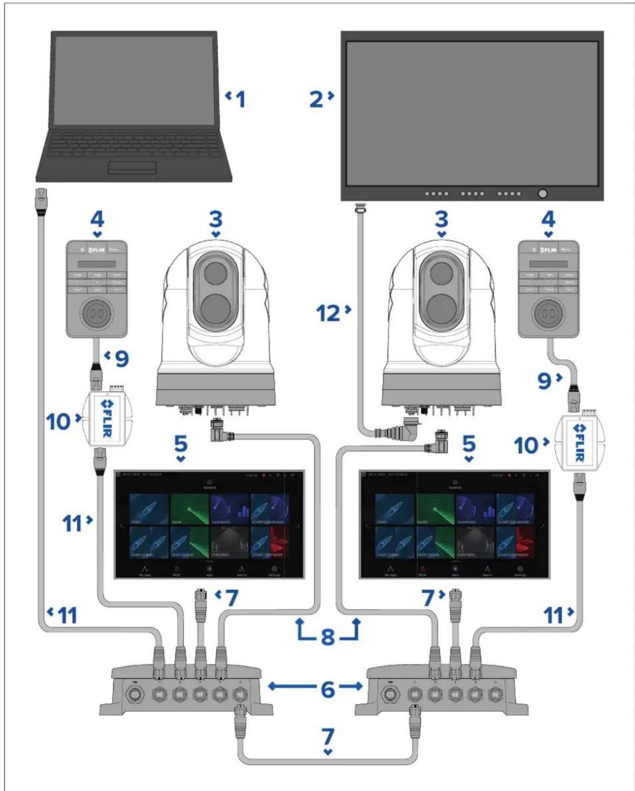
2.2Systemoverview
Thecamerahasaflexiblearrayofconnectionoptionstoenableyoutointegrateitwithyour electronicssystem.
With eight combination device and connections, you view and on the camera's image from them most convenient locations your vessel.
The following illustration shows a typical installation scenario more system configuration examples, ranging from small to large systems, refer to: 4.6 Network connections
For overview the camera's video connections, refer to: Video connections
Note: Powerconnections are not shown in this illustration. The camera and the other devices shown require their own dedicated power connection.
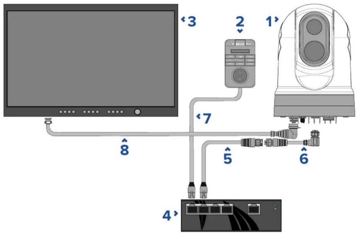
| 1 | M300Seriescamera |
| 2 | Joystickcontrolunit(e.g.JCU-2),availableseparately |
| 3 | HD-SDldisplay,availableseparatelyfromthird-partyretailers |
| 4 | EthernetnetworkswitchwithPoE,availableseparatelyas4141042 |
| 5 | RayNet-to-RJ45adaptercable(120mm/4.7in.)(suppliedwithcamera) |
| 6 | Right-angledRayNet-to-RayNetcable(3m/9.8ft)(suppliedwithcamera) |
| 7 | RJ45-to-RJ45networkcable,availableseparatelyinvariouslengths—refertop.103—FLIRnetworkingaccessories |
| 8 | Right-angledHD-SDlcable(withBNCconnectors)(3m/9.8ft)(supplied withcamera) |
2.3Productoverview
M300(singlepayload)
TheM300Seriesinglepayloadvariantisamaritimecameraequippedwitheithervisibleor thermalimagingsystem(dependingonchosenmodel),foruseonnearlyanykindofvessel.
The camerawillhaveoneofthefollowingtypesofimagingcore,dependingonthechosen model:
Visible provide a clear image daylight conditions for example visible cameracan help you maintain a watch of your surroundings, or zoom in on distant objects.
Thermalprovideleimaglow-lightando-lightconditions. For example, thermalcameracanhelpyounavigateatnightoridentifyobstaclesinareasoflow visibilityoreventotaldarkness.
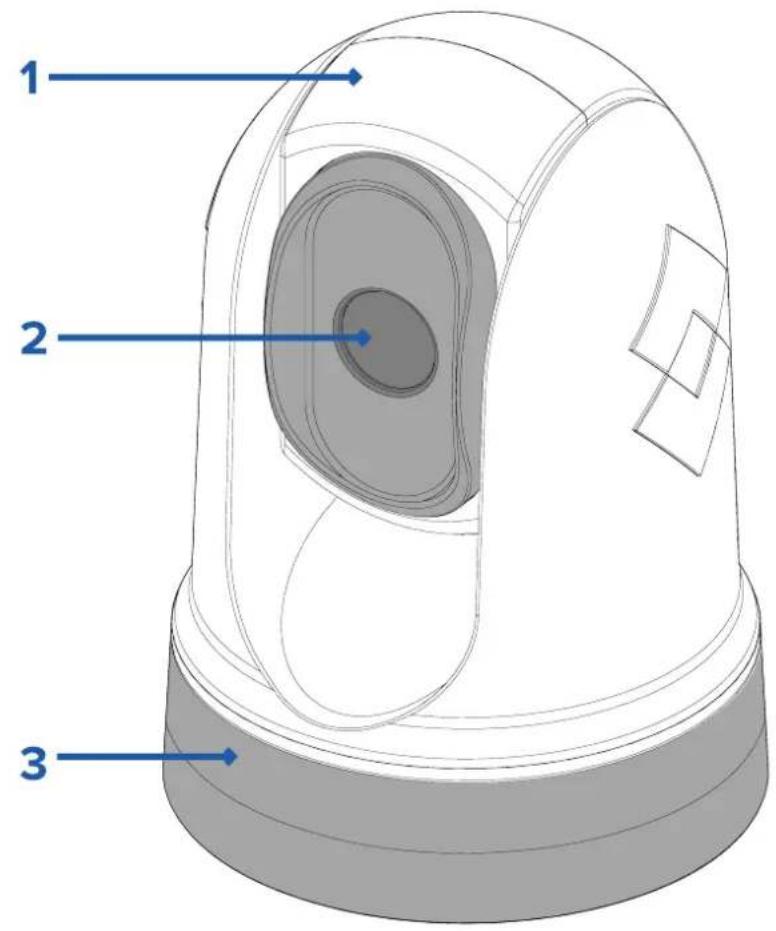
- Tiltassembly.
2.Cameralenswindow.
3.Panassembly.
TheM300Seriessystemhasthefollowingkeyfunctionsandfeatures:
- IPconnectivitytosimplifyinstallationandsystemintegration.
•4simultaneousvideooutputs,includinganH264-encodedIPvideostream—formore information,referto:p.47—Videoconnections - Panandtiltoperationswithdedicatedjoystickcontrolunit,multifunctiondisplay(MFD),orwebbrowser.
•2axismechanicalcamerastabilizationtosuitchangingconditions. - Presetmodes(Scenes)optimizedforprevailingconditions.
•ColorThermalVision(CTV)blendingmode—blendsthermalandvisiblelightcolorvideo feedsforenhancedidentificationofbuoys,vesselsandothertargetsatnight. - MultiSpectralDynamicImaging(MSX)blendingmode—addsspecificdetailsfromthe visiblelightvideofeedinrealtimetothethermalvideofeed,fordetectingandsharpening theedgesofobjectsinthethermalvideofeed.
- ClearCruise™ObjectDetection—intelligentthermalanalyticstechnology;providesaudible andvisualalertswhen“non-water”objectsareidentifiedinthescene.(Requiresa Raymarine®MFDrunningLightHouse™3.10softwareorlater.)
- ClearCruise™ AugmentedReality—featureplaceslayersofdigitalinformationdirectlyover thetopofthevideofeed.Vesseldataisusedtogenerateinformativetextandimages (flags)thatoverlapreal-lifeobjects.(RequiresaRaymarine®MFDrunningLightHouse™ 3.10softwareorlater.)
•Automaticwindowheaterstode-icethelenswindowincoldweather.
•12Vor24Vdcpower.
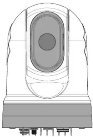
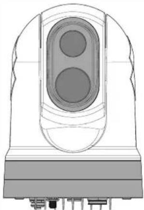
M300(dualpayload)
TheM300Seriesdualpayloadvariantisamaritimecameraequippedwithvisibleand thermalimagingsystem,foruseonnearlyanykindofvessel.
Dualpayloadcamerashave2separateimagingcores:
VisibleprovidealearoldimagidaylightconditionForexamplevisible cameracanhelpyoumaintainawatchofyoursurroundings,orzoominondistantobjects.
Thermalprovideleamaglow-lightando-lightconditionsExample thermalcameracanhelpyounavigateatnightoridentifyobstaclesinareasoflow visibilityoreventotaldarkness.
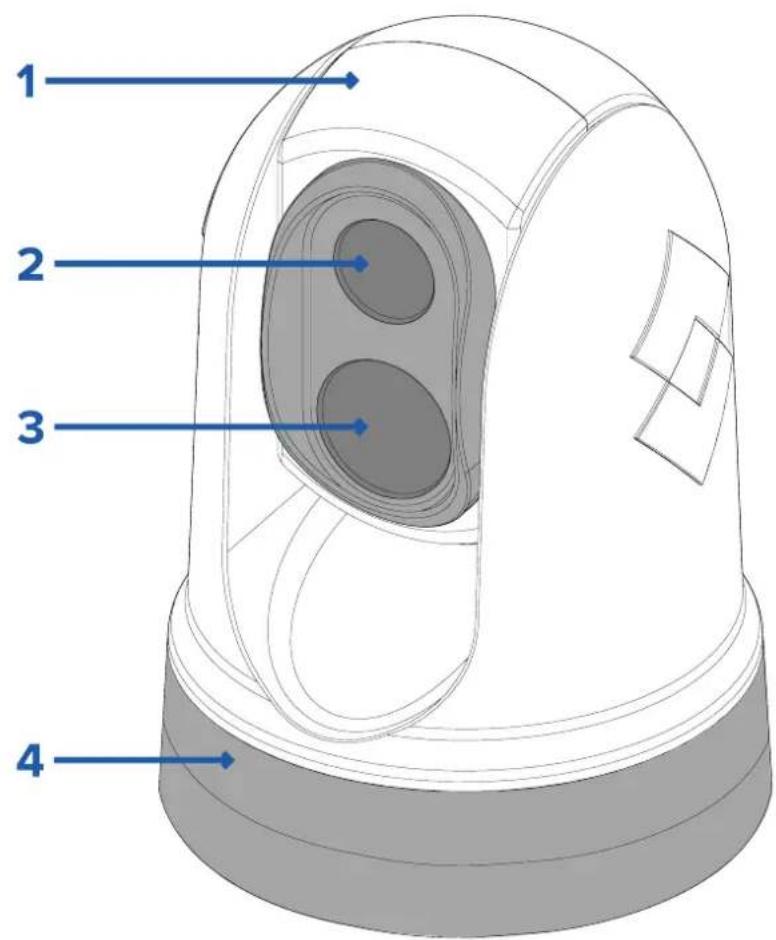
- Tiltassembly.
- Thermalcameralenswindow.
- Visible cameralenswindow
4.Panassembly.
TheM300Seriessystemhasthefollowingkeyfunctionsandfeatures:
- IPconnectivitytosimplifyinstallationandsystemintegration.
•4simultaneousvideooutputs,includinganH264-encodedIPvideostream—formore information,referto:p.47—Videoconnections - Panandtiltoperationswithdedicatedjoystickcontrolunit,multifunctiondisplay(MFD),orwebbrowser.
- 2axismechanicalcamerastabilizationtosuitchangingconditions.
-
Presetmodes(Scenes)optimizedforprevailingconditions.
•ColorThermalVision(CTV)blendingmode—blendsthermalandvisiblelightcolorvideo feedsforenhancedidentificationofbuoys,vesselsandothertargetsatnight. -
MultiSpectralDynamicImaging(MSX)blendingmode—addsspecificdetailsfromthe visiblelightvideofeedinrealtimetothethermalvideofeed,fordetectingandsharpening theedgesofobjectsinthethermalvideofeed.
- ClearCruise™ObjectDetection—intelligentthermalanalyticstechnology;providesaudible andvisualalertswhen“non-water”objectsareidentifiedinthescene.(Requiresa Raymarine®MFDrunningLightHouse™3.10softwareorlater.)
- ClearCruise™ AugmentedReality—placeslayersofvesseldatadirectlyoverthevideo feed, intheformoftextandimages (flags) thatoverlapreal-lifeobjects. (Requiresa Raymarine® MF DrunningLightHouse™ 3.10 softwareorlater.)
•Automaticwindowheaterstode-icethelenswindowincoldweather.
•12Vor24Vdcpower.
2.4Partssupplied
M300-Seriescamera
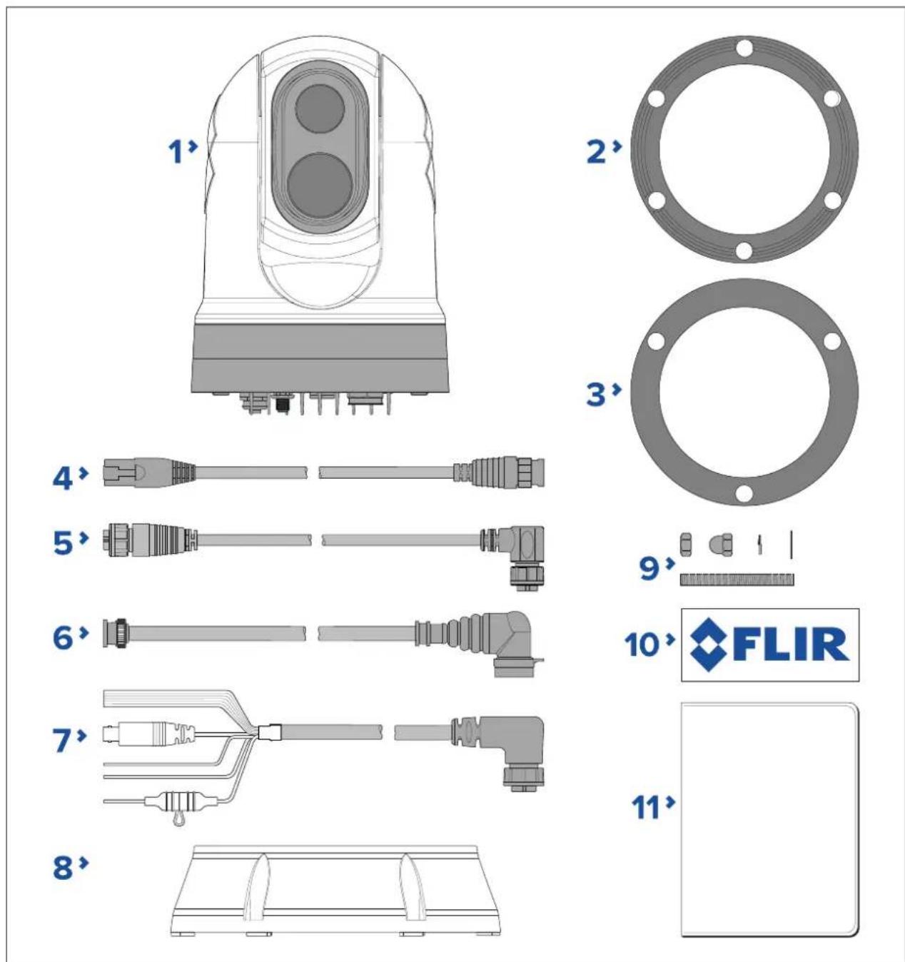
1.M300Camera
2. Camerabase-seal
3.Cameragasket
4.RayNet-to-RJ45adaptorcable120mm(4.72in.)
5.Right-angledRayNet-to-RayNetcable3m(9.8ft.)
6.Right-angledHD-SDIvideocable(withBNCconnectors)3m(9.8ft.)
7. Right-angled power/NMEA0183/videocable3m(9.8ft.)
8. Mountingriser
9.3xcamerafixings:nuts,domenuts,springandflatwashers,threadedstuds
10.2xself-adhesivedecals(forball-downmountingonly)
11.Documentationpack
Partssupplied—JCU-2(availableseparately)
Thepartssuppliedwiththeoptionalkeypadareshownbelow.
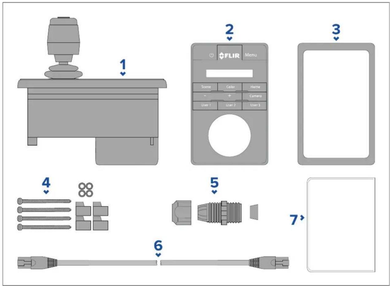
1.JCU-2keypad
2. Keypadmat
3. Mountinggasket
4.4xmountingscrews, rubberwashers, mountingclamps
5. Cableglandnut
6.RJ45-to-RJ45Ethernetcable,7.6m(25ft)
7.Documentationpack
2.5 Compatible joystick controllers (JCU)
Ajoystickcontrolunit(JCU)isavailabletopurchaseasanoptionalaccessory. Thisenables youtocontrolthecameraremotely.
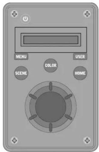
JCU-1
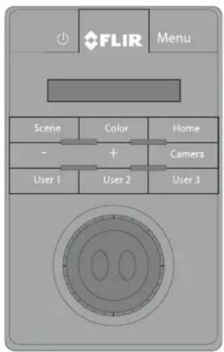
JCU-2
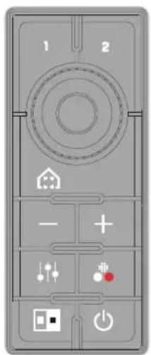
JCU-3
| JCUvariant | Partnumber | Moreinformation&manuals |
| JCU-1 | 500-0385-00 | www.raymarine.com/view/index.cfm?id=17603 |
| JCU-2 | 500-0398-10 | www.flir.com/products/jcu2/ |
| JCU-3 | A80510 | www.flir.com/products/jcu3/ |
2.6Compatiblemultifunctiondisplays
ThecameraimagecanbeviewedandcontrolleddirectlyfromaRaymarinemultifunction display(MFD).
Note: ARaymarine® LightHouseMFDisnotrequiredtouseanM300Seriescamera. However certain camera features may not be accessible without one.
ThisproductiscompatiblewiththefollowingRaymarine®LightHouse3multifunctiondisplays:
- eSSeries(upgradedfromLightHouse2toLightHouse3).
•gSSeries(upgradedfromLightHouse2toLightHouse3).
•Axiom
•AxiomPro
•AxiomXL
Multifunctiondisplaysoftwarerequirements
T ousethisproductwithaRaymarine®multifunctiondisplay(MFD),ensurethatyourMFDis runningVersion3.10orlateroftheLightHouse™3software.
Note:
- ThelatestLightHouse™MFDsoftwarecanbeobtainedbyvisiting www.raymarine.com/software.
Chapter3: Installation
Chaptercontents
•3.1 Generallocationrequirementsonpage26
•3.2 Toolsrequiredonpage27
•3.3Productdimensionsonpage28
•3.4Cameraorientationonpage31
•3.5Cameramountingonpage31
•3.6JCU-2Mountingonpage37
3.1 Generallocationrequirements
Importantconsiderationswhenchoosingasuitablelocationforyourproduct.
Theproductshouldbemountedwhereitwillbe:
- protectedfromphysicaldamageandexcessivevibration.
•wellventilated and away from heatsources.
Whenchoosingalocationfortheproduct,considerthefollowingpointstoensurereliable andtrouble-freeoperation:
- Access—theremustbesufficientspacetoenablecableconnectionstotheproduct, avoidingtightbendsinthecable.
Centelinethproduct should be mounted by youressel's centralness possible to provide asymmetrical view of all angles.
- Vessel'scenterline.
Clearviewthproduct should have cleariew the water within minimal obstruction tothe360° view.
- Electricalinterference—theproductshouldbemountedfarenoughawayfromany equipmentthatmaycauseinterferencesuchasmotors,generatorsandradiotransmitters/receivers.
MagneticcompassrefethCompassafdistancesectionthisdocument foradviceonmaintainingasuitabledistancebetweenthisproductandanycompasses onyourvessel.
Heightthproduct should be mounted by a practical giving review will directions.
- Power—tokeepcablerunstoaminimum, the product must belocated as close as possible to the vessel's dcpowersupply.
Mountingurfaceensurthproductadequatelysupportedacursurface.
Refetheeighinformatioprovide the technical specification of the product and ensure that the intended mountingsurface is suitable for bearing the product weight. Do NOTmountunits or cutholes in places which may damage the structure of the vessel.
Compasssafedistance
T opreventpotentialinterferencewiththevessel'smagneticcompasses,ensureanadequate distanceismaintainedfromtheproduct.
Whenchoosingasuitablelocationfortheproductyoushouldaimtomaintainthemaximum possibledistancefromanycompasses.T typicallythisdistanceshouldbeatleast1m(3.3ft) inalldirections.Howeverforsomesmallervesselsitmaynotbepossibletolocatethe productthisfarawayfromacompass.Inthissituation,whenchoosingtheinstallation locationforyourproduct,ensurethatthecompassisnotaffectedbytheproductwhen itisinapoweredstate.
3.2 Toolsrequired
The following tools are required for installation.
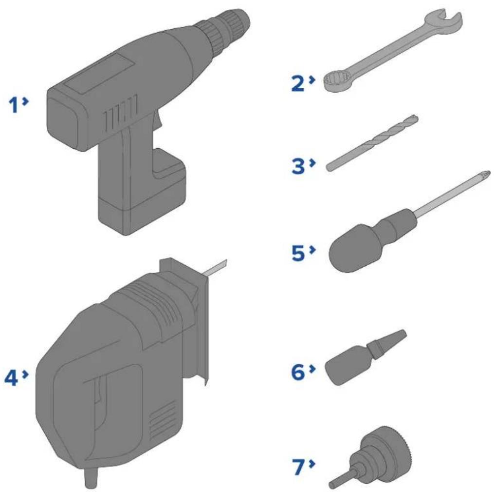
| 1 | Drill |
| 2 | 10mm(0.39in.)spanner |
| 3 | Drillbit(appropriatesizedependentonthicknessandmaterialofmounting surface) |
| 4 | Jigsaw |
| 5 | Pozi-drivescrewdriver |
| 6 | Thread-lock |
| 7 | 50mm(2in.)Holesaw |
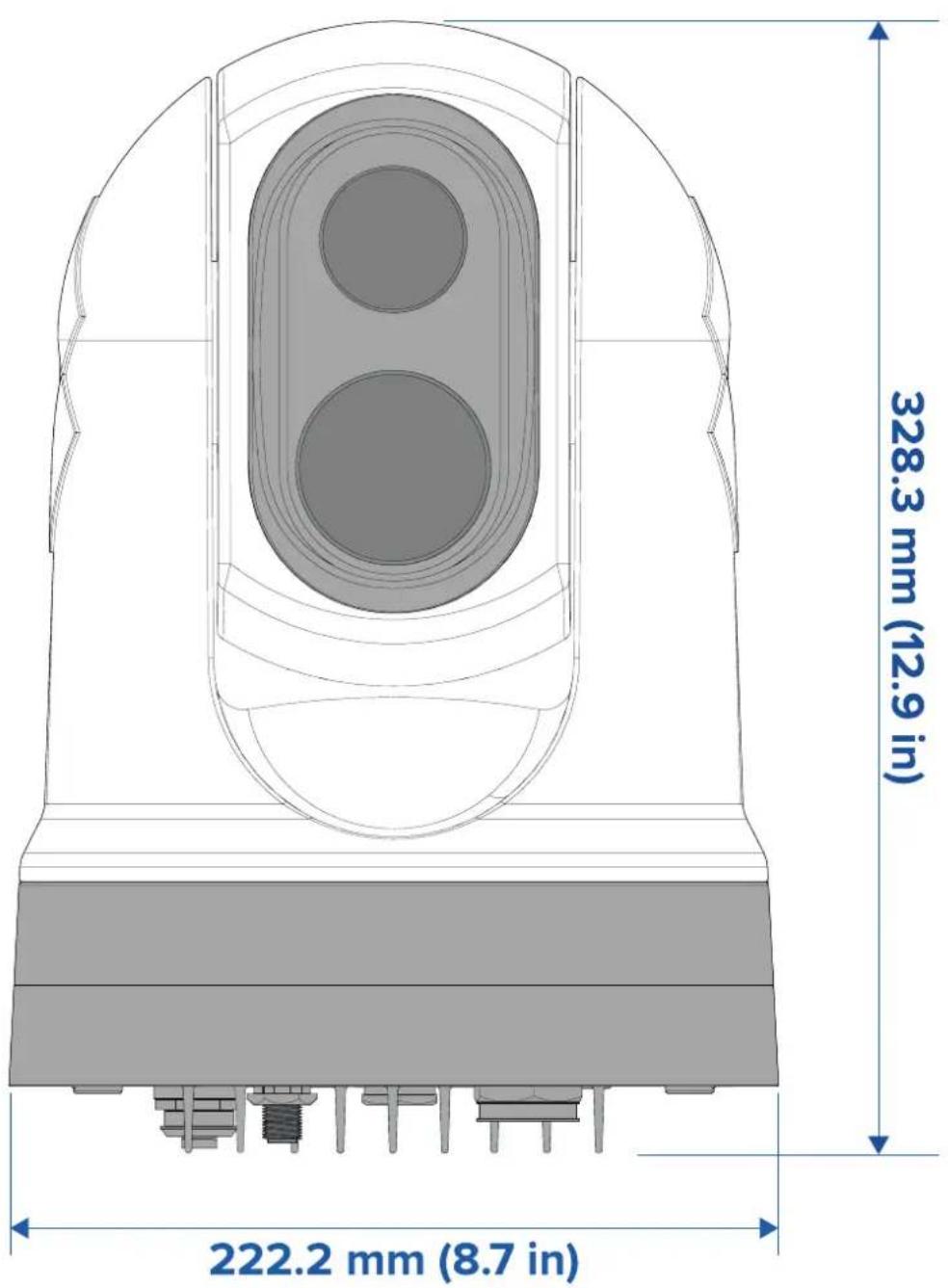
3.3Productdimensions
M300Series
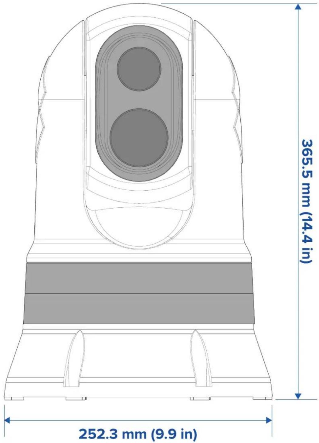
M300Serieswithoptionalmountingriser
other
| Dimension | Value | | ----------------- | --------- | | Width (mm) | 365.5 | | Height (in) | 252.3 |Note: Based diameter with riser base-sealfitted is 254 mm (10 in).
JCU-2(availableseparately)
Productdimensions
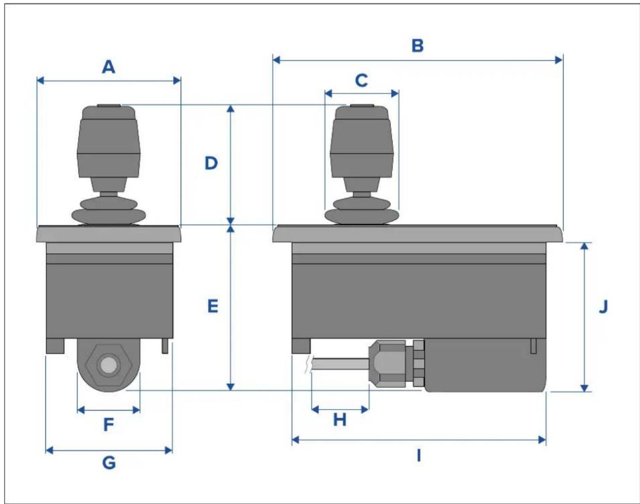
| DimensionMeasurement | |
| A | 90.8mm(3.57in.) |
| B | 142.8mm(5.62in.) |
| C | 48.9mm(1.93in.) |
| D | 75.8mm(2.98in.) |
| E | 88.7mm(3.49in.) |
| F | 37.9mm(1.49in.) |
| G | 77.5mm(3.05in.) |
| H | 7.6m(25ft.) |
| I | 128.5mm(5.06in.) |
| J | 77.0mm(3.03in.) |
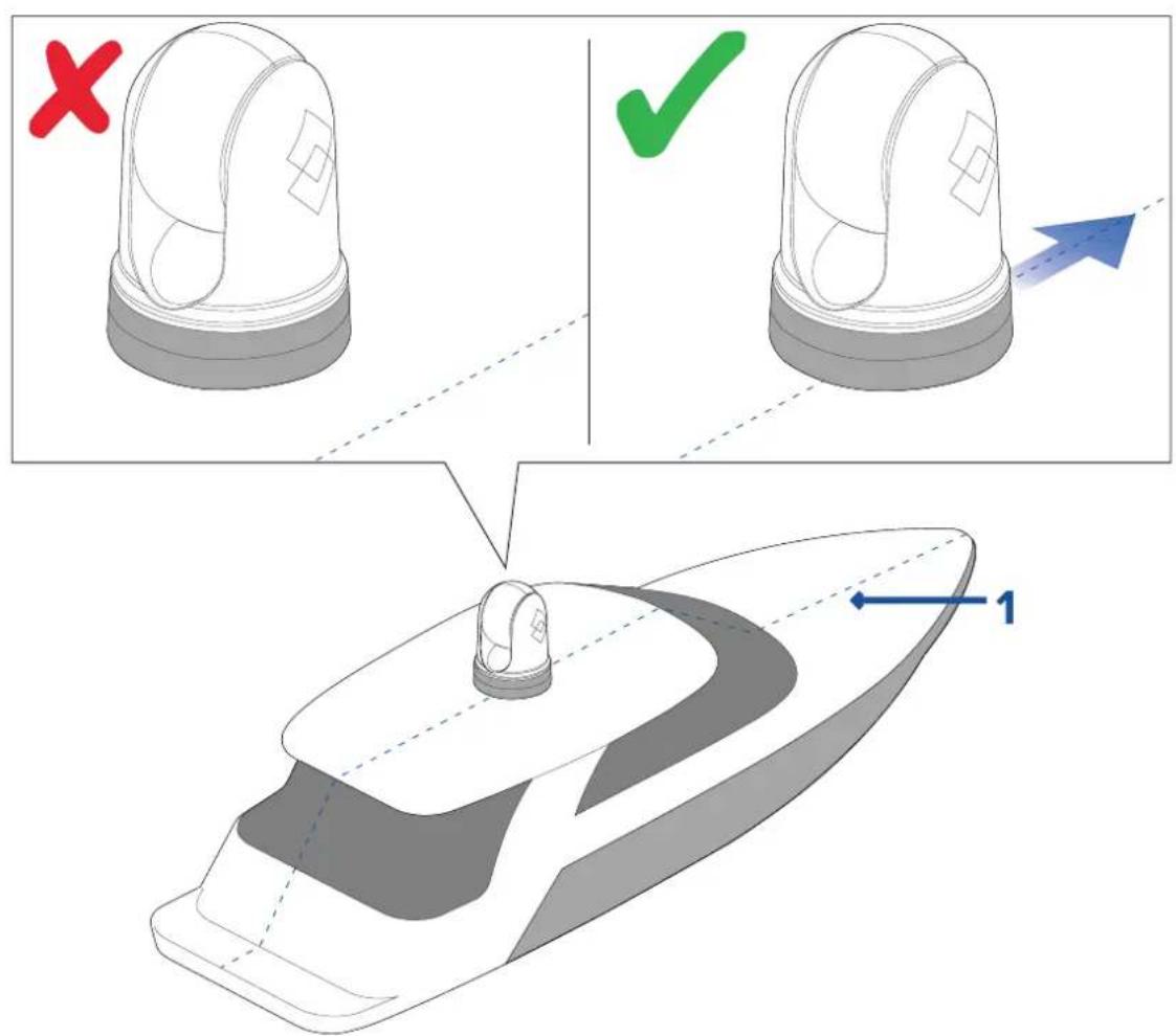
3.4Cameraorientation
Thecameracanbemountedin2orientationsinformallyknownas"Ballup"and"Balldown".
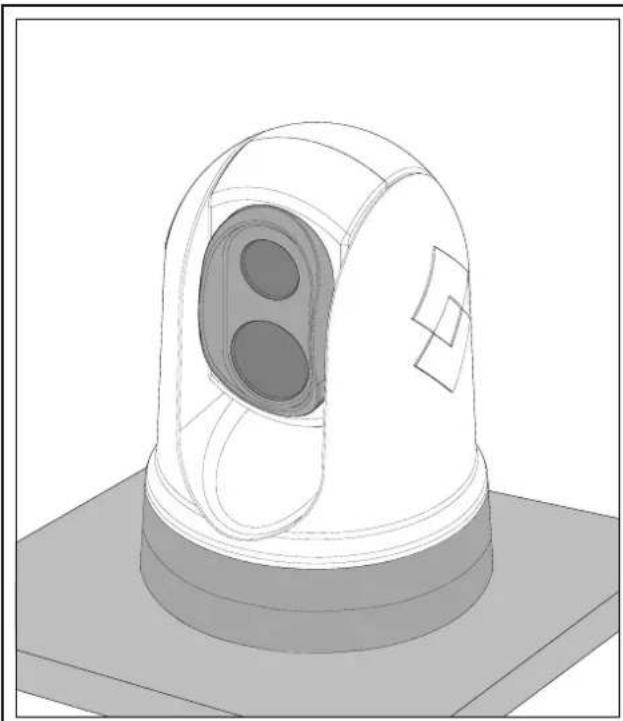
natural_image
3D technical illustration of a mechanical sensor or detection device with a dome-shaped top and central lens (no text or symbols)Ball-up: Thecameraismountedontopof themountingsurface.
natural_image
3D technical illustration of a mechanical component with internal oval features and a flat base (no text or symbols)Ball-down: Thecameraissuspendedupside down, below themountingsurface.
Thedefaultvideoimageorientationisfortheball-upconfiguration;ifthecameraistobe mountedintheball-downconfigurationthenthevideoimagemustberotated.T orotate thevideoimage,youmusteither:
- usethecamera'swebbrowseruserinterfaceosettheappropriateoption(see p.75—Webinterfaceoperation r
- ifyoursystemincludesaRaymarinemultifunctiondisplay(MFD),usetheMFD'sCameraapptosettheappropriateoption(refertoyourMFDOperationInstructions).
3.5 Cameramounting
Locationrequirements
Whenplanningtheinstallationlocation,considerthefollowingpoints:
• Thecameraiswaterproof, and appropriate for abovedecksmounting.
- Whenmountingthecameryainaball-downposition,ensurethatthecameraisinstalled withadequatedrainagesothatstandingwaterdoesnotcollectinthebase.
- Ensure the camera is installed in a location that will allow it to be accessed for regular periodic cleaning (fresh-waterrinse), inspection of mounting point integrity and mechanical soundness, and preventative maintenance.
•Theunderside(inside)ofthecompartmentordeckontowhichthecameraismountedmust beweather-tight.Y oumustensureprotectionfromwateringresstocablesandconnections.
•Themountingsurfacemustbehorizontal.
- If you cannot access both sides of themountings surface, then you will need to mount the camera "topdown" using themounting risers supplied with the camera.
- The camerashould bemountedashighaspractical, but without interfering with any radar, navigational or communicationselectronics.
- Choose allocation that will provide them most unobstructed view in all directions.
- Choose allocation asclosetothevessel'scenterlineaspossible. This provides a symmetrical view when looking forward or aft.
- Selectalocationforthecamerathatisatleast1m(39.4in.)fromanymagneticcompass.
- Selectalocationthatisatleast1m(3ft)fromdevicesthatmaycauseinterference,suchasmotors,generatorsandradiotransmitters/receivers.
- IfinstallinganoptionalJCU,selectalocationfortheJCUthatisatleast1m(39.4 in.)fromanymagneticcompass.
Note: If you want to make a possible connection to the camera before mounting it your vessel (fore example, to test the camera), first attach the three-threaded student the base (sep.32 Mounting camera). This will protect the able connector on the base of the camera, and also provides a stable platform, helping to prevent damage caused by the unit rolling off the edge of the works surface.
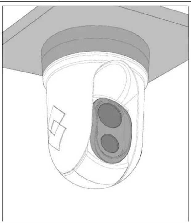
Mountingthecamera
Usetheseinstructionstomountthecameraunitinposition.
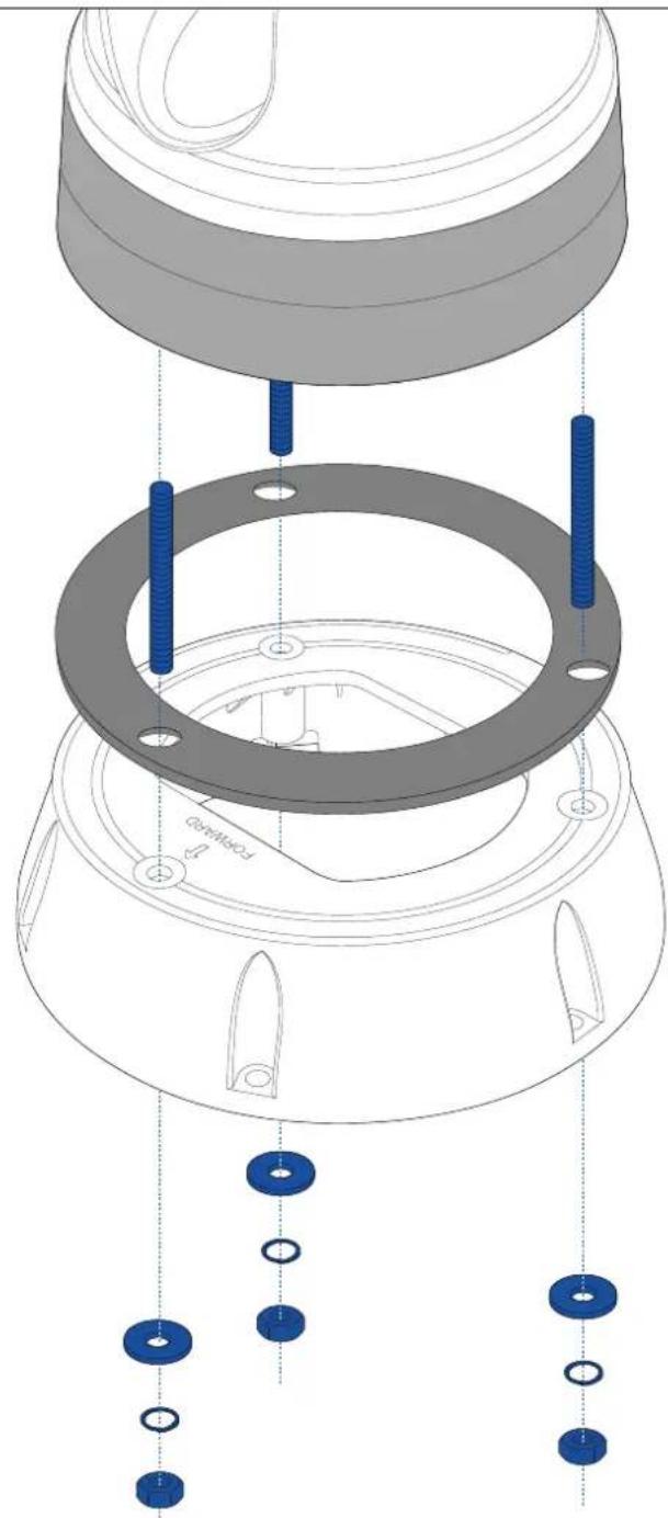
natural_image
Technical diagram showing assembly of a mechanical component with blue bolts and housing (no text or symbols)- Using the templates supplied, mark and drill the holes form mounting the camera.
Mountingholescarepoints:
- Checkthedimensionsofanyprintedtemplate(toensurethatthetemplateisprintedto thecorrectscale)prioritodrillinganyholes.
- Notetheareaatthefrontofthecamera, and makesurethetemplateisoriented properlyrelativetothebowofthevessel. Thisisaffectedbywhetherthecamera istobemountedball-uporball-down.
- Installthe3xthreadedstudsintothebaseofthecamerawiththread-lockingcompound. Ifrequired,youcanusestudsofadifferentlenghtosuityourinstallation.
3.Slidethefoamgasketoverthethreadedstuds, andstickitfirmlyintoplaceonthe camera'sbase. - Connect the powers up supply cable, BNC videocable and network cable to the camera, and thread the cable through the central hole.
- Placethecameraonthemountingsurfacesothethreadedstudsextendthroughthe drilledholes.
- Maketherequiredconnectionswiththefreeendsofthecables.
- Slideaflatwasher, and thenaspringwasher, ontoeachstud.
- Secure the camerabody to themountings surface with the supplied nuts, ensuring that the seal remains correctly positioned on the camera's base.
Tightenthenutstoatorqueof5.0N·m(3.7lbf·ft).
Domecappednutsareprovidedforaneatersolutionwherethemountingisexposedto view.
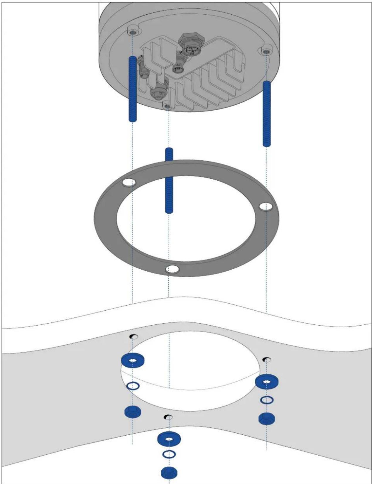
Mountingthecamerawiththeoptionalmountingriser
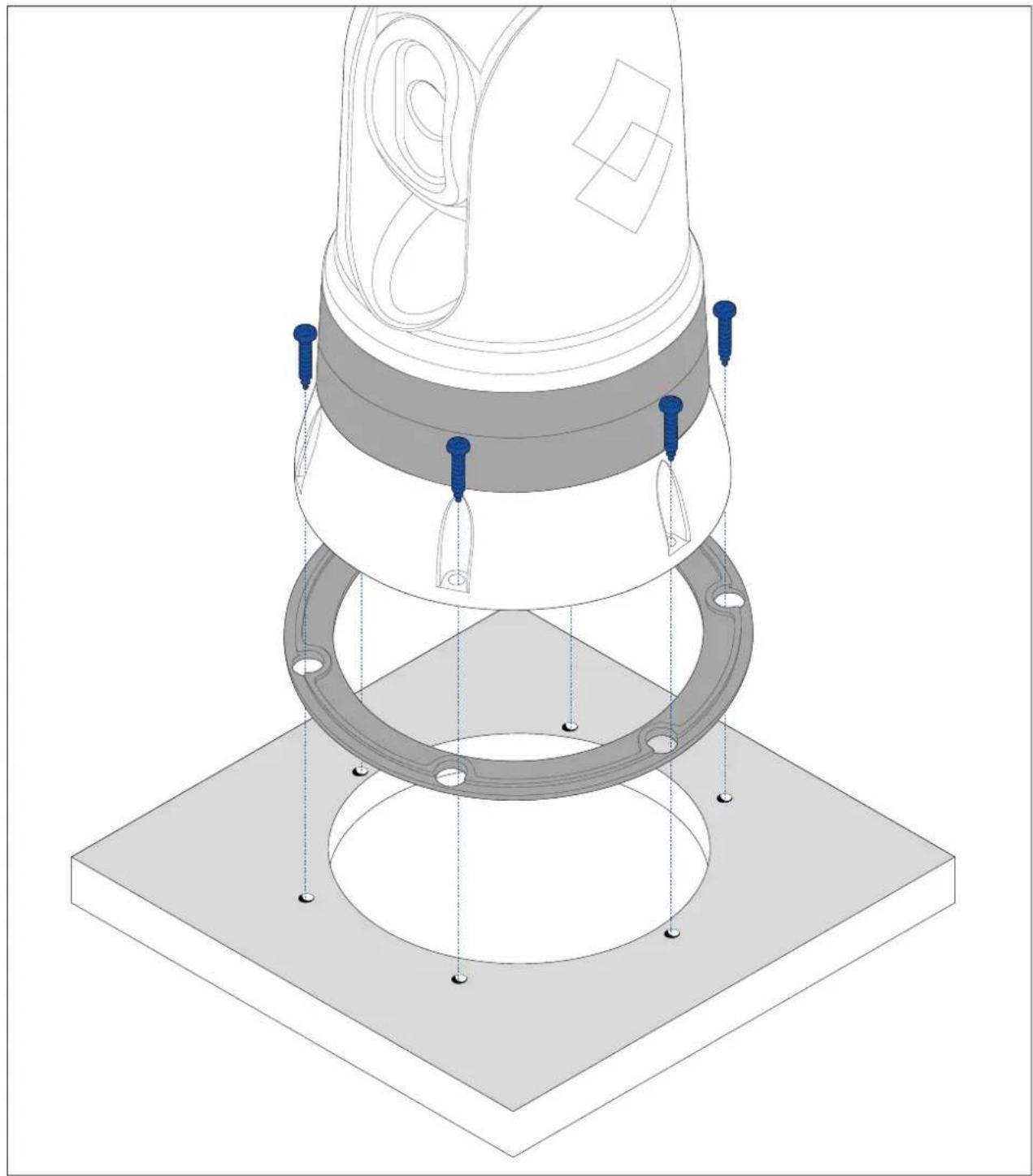
Theoptionalmountingriserisusedwhenaccesstotheundersideofthemountingsurfaceis restricted. Usetheinstructionsbelowtomountthecameraunitusingthemountingriser.
natural_image
Exploded view diagram of a mechanical assembly showing internal components and mounting holes (no text or symbols)-
Using the template provided, mark and drill the holes form mounting theriser.
-
Notethecameraforwardmarkingonthetopsurfaceoftheriser.Y oumustensure thattheriserismountedsothatthecameraisorientedproperlyrelativetothebow ofthevessel.
-
Onlydrilltheoptionalcableroutingholeinthemountingsurfaceifyouintendoroute thecablesthroughthebaseoftheriser, rather than through thesideoftheriser.
-
Installthe3xthreadedstudsintothebaseofthecamera.Donotusethreadlocking compound,asthismaydamagetheplasticriser.
3.Slidethefoamgasketoverthethreadedstuds,andpushitfirmlyintoplaceonthe camera'sbase.
- Placethecameraontopoftheriser, sothethreadedstudsextendthroughthethree holesintheriser'stopsurface. Check that the foamgasket remains firmly in place.
- Notethecameraforwardmarkingonthetopsurfaceoftheriser.Y oumustensure thattheriserismountedsothatthecameraisorientedproperlyrelativetothebow ofthevessel.
- Placetherubberbasesealonthebottomoftheriser.
6.Slideaflatwasher, and thenaspringwasher, ontoeachstud.
- Secure the camerabody to otheriser with the supplied nuts, ensuring that these are remains correctly positioned on the camera's base.
Tightenthenutstoatorqueof3.7N·m(2.7lbf·ft).
-
Connect the powers up supply cable, BNC cable and network cable to the camera, then loop the cables round with in theriser bases so that they can be threaded through the bottom of theriser, and into the cablerouting holedrilled in themountings surface.
-
Ensuretheriser-basesealispositioned correctly, and then fastenthe camera-riser assembly to themountingsurface using fasteners appropriate for the surface's thickness and material. Donotusethreadlocking compound, asthismaydamagetheplasticriser.
Y oumustensureawatertightsealbetweentheriserbaseandthemountingsurface.Y ou mayuseamarine-gradesealantasanalternativetothesuppliedmountinggasket.
Note:
- Ifitisnotpossibletoroutethecameracablesthroughthemountingsurface,cutahole inthesideoftheriser,androutethecablesthroughtherisersidewall.Y oumayneedto loopthecablesaroundwithintheriserbase,sothattheycanbepassedthroughthe holeyouhavecutinthesideoftheriser.
- Ifroutingthecameracablesthroughtherisersidewall, and thecameraismounted ball-up, do NOT sealtheriser basewith either the supplied gasket, or sealant. Sealing may result in waterpooling inside aetheriser.
- Ifroutingthecameracablesthroughtherisersidewall, and thecamera is mounted ball-down, do NOT seal the connection between the camerabase and the top surface of theriser with the supplied gasket. Sealing may result in water pooling inside aetheriser.
natural_image
Isometric technical diagram of a mechanical assembly with layered components and mounting base (no text or symbols)3.6JCU-2Mounting
Note:
The JCU-2 joystick control unit is available as an optional accessory (500-0398-10).
Locationrequirements
When planning the installation location, consider the following points:
- Selectapositiononyourvesselthatisclosetoadisplayshowingthecamervideooutput.
- Ensuretheunitismountedatleast1m(39.4")awayfromanyequipmentfittedwithamagneticcompass.
•Theunitcanbemountedtoadashorothersurfaceinanyorientation.
- Considercablelengthsandcablerouting.
Removingthekeypadmat
T ogainaccesstothemountingholelocations,thekeypadmatmustberemoved.
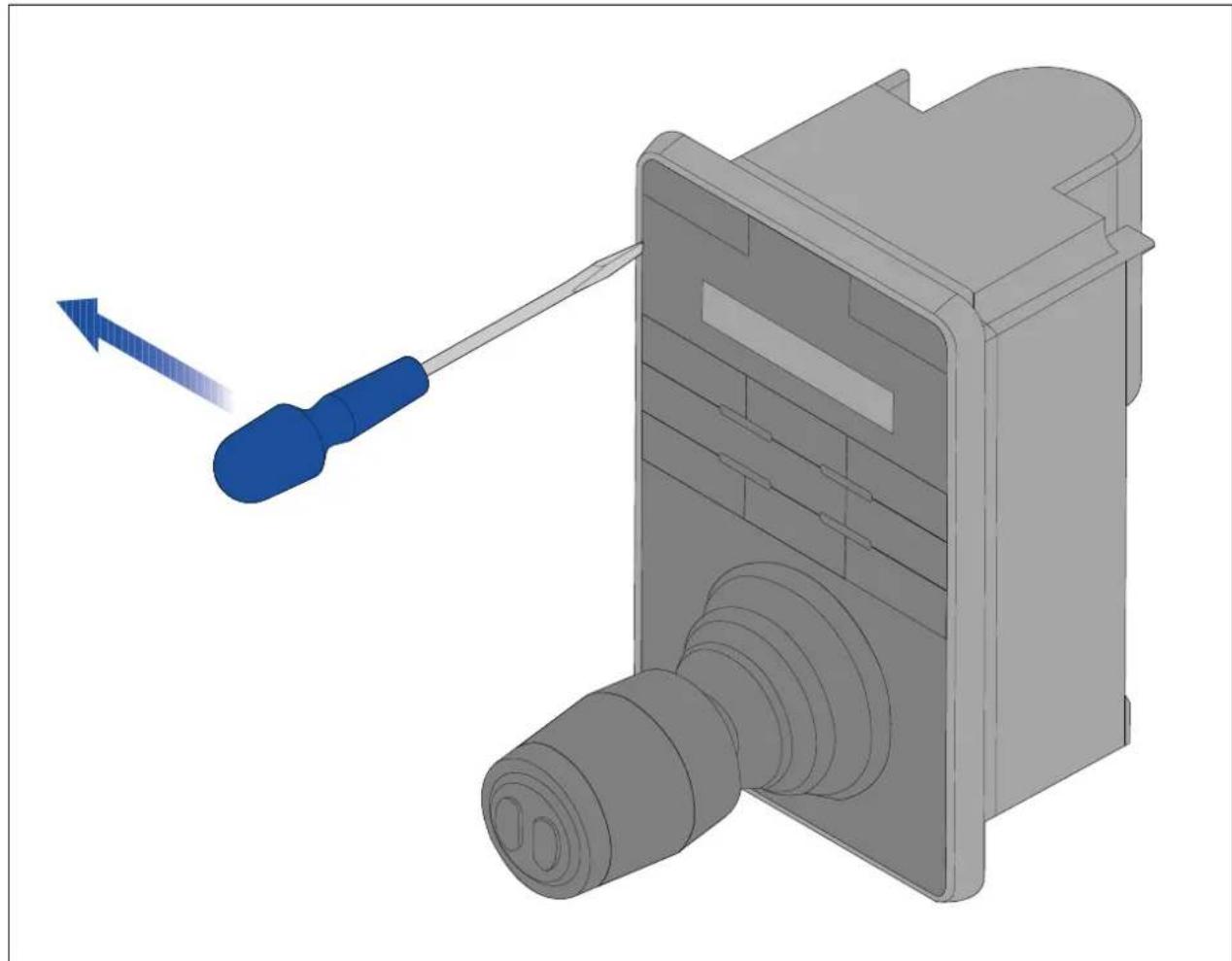
natural_image
3D mechanical assembly diagram showing a blue screwdriver inserted into a component with a blue arrow indicating direction (no text or symbols present)Note:T ohelppreventscratchingtheproduct,coverthetipofyourscrewdriverbladewithasmallpieceofinsulationtape.
-
Usingathin, flatbladed screwdriver insert the tip of the screwdriver into the gap between the edge of the keypad mat and the keypad housing.
-
Gentlyleverthekeypadmatawayfromthekeypadtoreleasethekeypadmat.
T akecarenottobendthekeypadmatduringremoval.
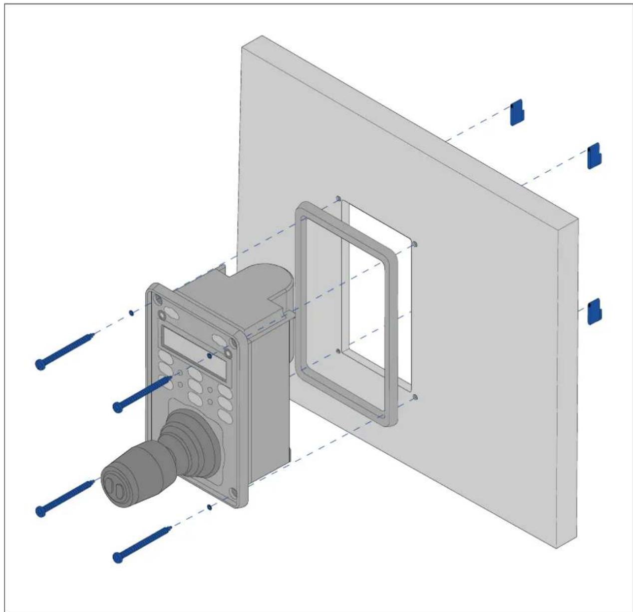
Flushmountingthekeypad
Flushmountingprovidesasleekinstallationwheretheproductanddashareflush,withonly thebuttonsandRotarycontrollerprotrudingfromthedash.Flushmountingrequiresthe mountingsurfacetoberebated.
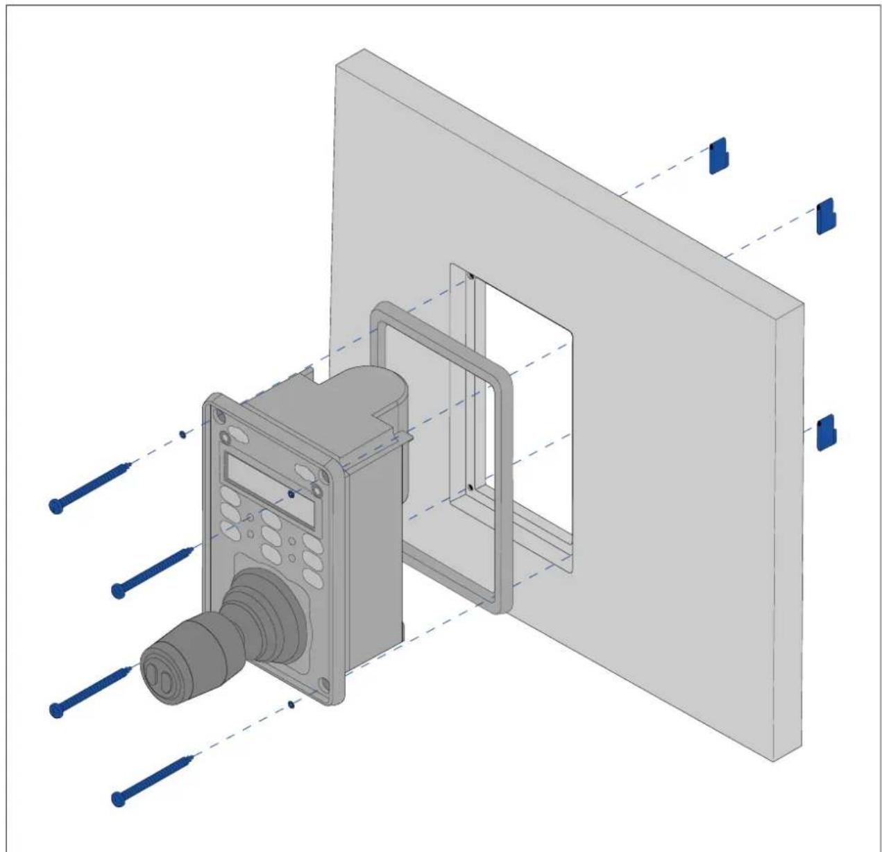
natural_image
3D CAD model of a mechanical assembly with a component and transparent panel, showing alignment lines (no text or symbols)- Checktheselectedlocationfortheunit.Aclear,flatareawithsuitableclearancebehind thepanelisrequired.
- Before modifying themountingsurface, refertothedimensionssupplied in this document to ensure there is enoughspace for the unit and all cables.
- Fixthesuppliedmountingtemplatetotheselectedlocation, usingmaskingorself adhesivetape.
- Drill4holesasindicatedonthemountingtemplatetoacceptthefixings.
- Using asuitableholesaw (thesize and position is indicated on the template), make a hole in each corner of the cut-out area.
- Using asuitablesaw, cut along the inside edge of the cut-out line.
- UsingaRouter, followtheFlushmountrebateline, tocutoutarebatetothespecified rebatedepth, asindicatedonthetemplate.
- Ensure that the unit fits into other removed area and then removeroughedges.
- Placethesuppliedgasketontotherearofthekeypad, ensuringthemountingholes arealigned.
- Connecttherelevantcablestotheunit.
- Placethekeypadintotherebateandsecureusingthefixingsprovided.
Note: The appropriatetighteningtorqueanddrillbitsizetousedependsonthethickness of themountingsurfaceandthetypeofmaterialitismadefrom.
Note: Thesuppliedgasketprovidesasealbetweentheunitandasuitablyflatandstiff mountingsurfaceorbinnacle. Thegasketshouldbeusedinallinstallations. Itmayalso benecessarytouseamarine-gradesealantifthemountingsurfaceorbinnacleisnot entirelyflatandstifforhasaroughsurfacefinish.
Surfacemountingthekeypad
Surfacemountingprovidesauniforminstallationwheretheproductsprotrude,usuallybythe thicknessofthebezel,fromthemountingsurface.
natural_image
3D CAD rendering of a mechanical assembly with labeled components and alignment lines (no text or symbols)- Checktheselectedlocationfortheunit.Aclear,flatareawithsuitableclearancebehind thepanelisrequired.
- Before modifying themountingsurface, refertothedimensionssupplied in this document to ensure there is enoughspace for the unit and all cables.
- Fixthesuppliedmountingtemplatetotheselectedlocation, usingmaskingorself adhesivetape.
- Drill4holesasindicatedonthemountingtemplatetoacceptthefixings.
- Using asuitableholesaw, makeaholeineachcornerofthecut-outarea.
- Using asuitablesaw, cut along the inside edge of the cut-out line.
- Ensure that the unit fits into other removed area and then removeroughedges.
-
Placethesuppliedgasketontotherearofthekeypad, ensuringthemountingholes arealigned.
-
Connecttherelevantcablestotheunit.
Formoreinformationonfittingthecablereferto
- Secureusingthefixingsprovided.
Note:
The appropriatetighteningtorqueanddrillbitsizetousedependsonthethicknessofthe mountingsurfaceandthetypeofmaterialitismadefrom.
Note:
Thesuppliedgasketprovidesasealbetweentheunitandasuitablyflatandstiffmounting surfaceorbinnacle. The gasketshouldbeusedinallinstallations. It may also be necessary to use amarine-gradesealantifthemountingsurfaceorbinnacle is not entirely flat and stiff for hasaroughsurface finish.
Fittingthekeypadmat
Y oushouldfitthekeypadmataftertheunithasbeensecuredtothemountingsurface.
- Ensure the keypad matisorientated correctly.
2.Slidethekeypadmatoverthejoystickandclickitintoplace,startingwithoneofthelongeredges.
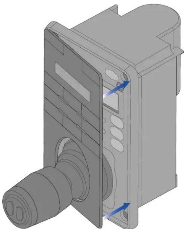
natural_image
3D mechanical component diagram showing internal structure with no visible text or symbols- Closetheoppositeendofthekeypadmatintothekeypad, ensuring that the tabslides into thenotch provided. Pushallofthetabsonthelongersides into their notches (you should hear a clickase ach tabengages).
Chapter4:Connections
Chaptercontents
•4.1 Generalcablingguidanceonpage44
•4.2Connectionsoverviewonpage45
•4.3Videoconnectionsonpage47
•4.4NMEA0183connectiononpage49
•4.5T ypicalsystemsonpage51
•4.6Networkconnectionsonpage51
•4.7Powerconnectiononpage59
4.1 Generalcablingguidance
Cabletypesandlength
Itisimportanttousecablesoftheappropriatetypeandlength
- Unless otherwise stated use only standard cables of the correct type, supplied by FLIR.
- Ensure that anynon-FLIRcables are of the correct quality and gauge. Forexample, longer power cablerunsmay require larger wire gaugestominimize voltagedropalongtherun.
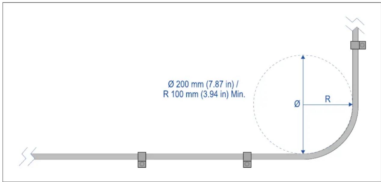
Cablerouting
Cablesmustberoutedcorrectly,tomaximizeperformanceandprolongcablelife.
- DoNOTbendcablesexcessively. Whereverpossible, ensureaminimumbenddiameter ( ) of 200mm(7.87in)/minimumbendradius(R) of 100mm(3.94in).
- Protectallcablesfromphysicaldamageandexposuretoheat.Usetrunkingorconduit wherepossible.DoNOTruncablesthroughbilgesordoorways,orclosetomoving orhotobjects.
- Securecablesinplaceusingcableclipsorcableties.Coilanyexcesscableandtieit outoftheway.
- Whereacablepassesthroughanexposedbulkheaderdeckhead,useasuitable watertightfeed-through.
- DoNOTruncablesneartoengineosorfluorescentlights.
•Alwaysroutedatacablesasfarawayaspossiblefrom:
-otherequipmentandcables,
–highcurrentcarryingACandDCpowerlines,
-antennas.
Strainrelief
Useadequatestrainreliefforcablingtoensurethatconnectorsareprotectedfromstrainand willnotpulloutunderextremeseaconditions.
Circuitisolation
Appropriate circuit isolation is required for installations using both AC and DC current:
- Alwaysuseisolatingtransformersoraseparatepower-invertertorunPC's,processors, displaysandotherssensitiveelectronicinstrumentsondevices.
- AlwaysuseanisolatingtransformerwithWeatherFAXaudiocables.
- Alwaysuseanisolatedpowersupplywhenusinga3rdpartyaudioamplifier.
•AlwaysuseanRS232/NMEAconverterwithopticalisolationonthesignallines.
- AlwaysmakesurethatPC'sorother sensitive electronic devices haveadedicated powercircuit.
Cableshielding
Ensure that cableshielding is not damaged during installation and that all cables are properly shielded.
HD-SDIcableconnection
WhenmakingtheHD-SDIconnectiontothecamerausingthesuppliedcable,ensurethatthe rubbershroudsurroundingthecableconnectorissecuredwithcableties(notsupplied),once fittedtotheconnector.Fitonetietotheshroudatthepointwherethecableentersthe bottomoftheshroud,andanotheriearoundtheshroudwhereitcoverstheconnectoritself.
4.2Connectionsoverview
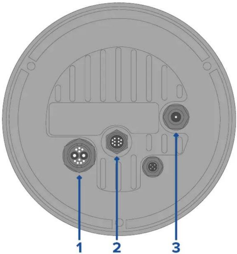
Y ourproductincludesthefollowingconnectors
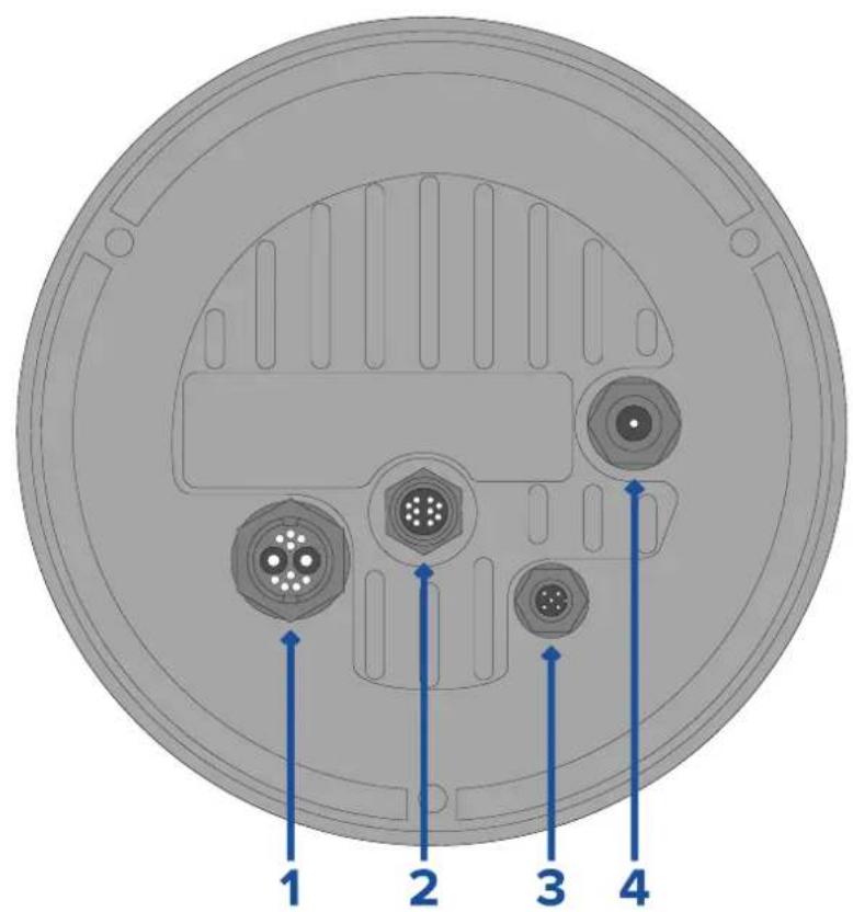
| ConnectorConnectstoSuitablecables | ||
| 1)Power/NMEA0183/CompositevideoNote:TheNMEA0183 wiresarenotcurrently active,andwillbe supportedinafuture softwareupdate. | •12/24Vdcpowersupply•NMEA0183in/out•Compositevideo(onfemale BNCconnector) | •Right-angledpowersupply cable(supplied) |
| 2)RayNet | •RayNetnetworkdevice•RayNet-to-RJ45adapter cable(supplied)•Right-angledRayNet-to-RayNetcable(supplied) | |
| 3)DeviceNetNote:TheDeviceNet connectorisnotcurrently active,andwillbe supportedinafuture softwareupdate. | •DeviceNetnetworkdevice/backboneSeaTalknetworkdevicebackbone | •DeviceNet-to-DeviceNet cable•DeviceNet-to-SeaTalkng adaptercable |
| 4)HD-SDI | device,orHDMIvia suitableconverterand cablesavailableseparately fromthird-partyretailers. | •HD-SDIderable (supplied),terminatedin BNCconnectors. |
FonorinformationavailableablesefetChapterSpareanAccessories
| Note: The ableshould beouted are the vesseb connection. Alternatively you must ensure that all connections are watertight. |
| Not how airt makeable connection the amer be fore mounting your vessel (forexample,totestthecamera),firstattachthe3threadedstudstothebase. This will helptoprotect the cable connectorsonthebaseofthecamera,and also provides a stable platform,helpingtopreventdamagecaused by the unit rolling off the edge of the works surface. |
Connectingables
Followthestepsbelowtoconnectthecable(s)toyourproduct.
- Ensure that the vessel's powersupply is switched off.
- Ensure that the device being connected has been installed in accordance with the installation instruction supplied with that device.
Ensuring correct orientation pushable connectors fully on the corresponding connectors. - If applicable, engage any locking mechanism to ensure secure connection.
- Ensure any bare ended wire connections are suitably insulated to prevent corrosion duetowateringress.
Orientationofright-angledconnectors
Whenmakingconnectionsusingthesuppliedright-angledpowerandnetworkcables,ensure thatyouorienttheconnectorscorrectlywithrespecttothethermalcamerabase.
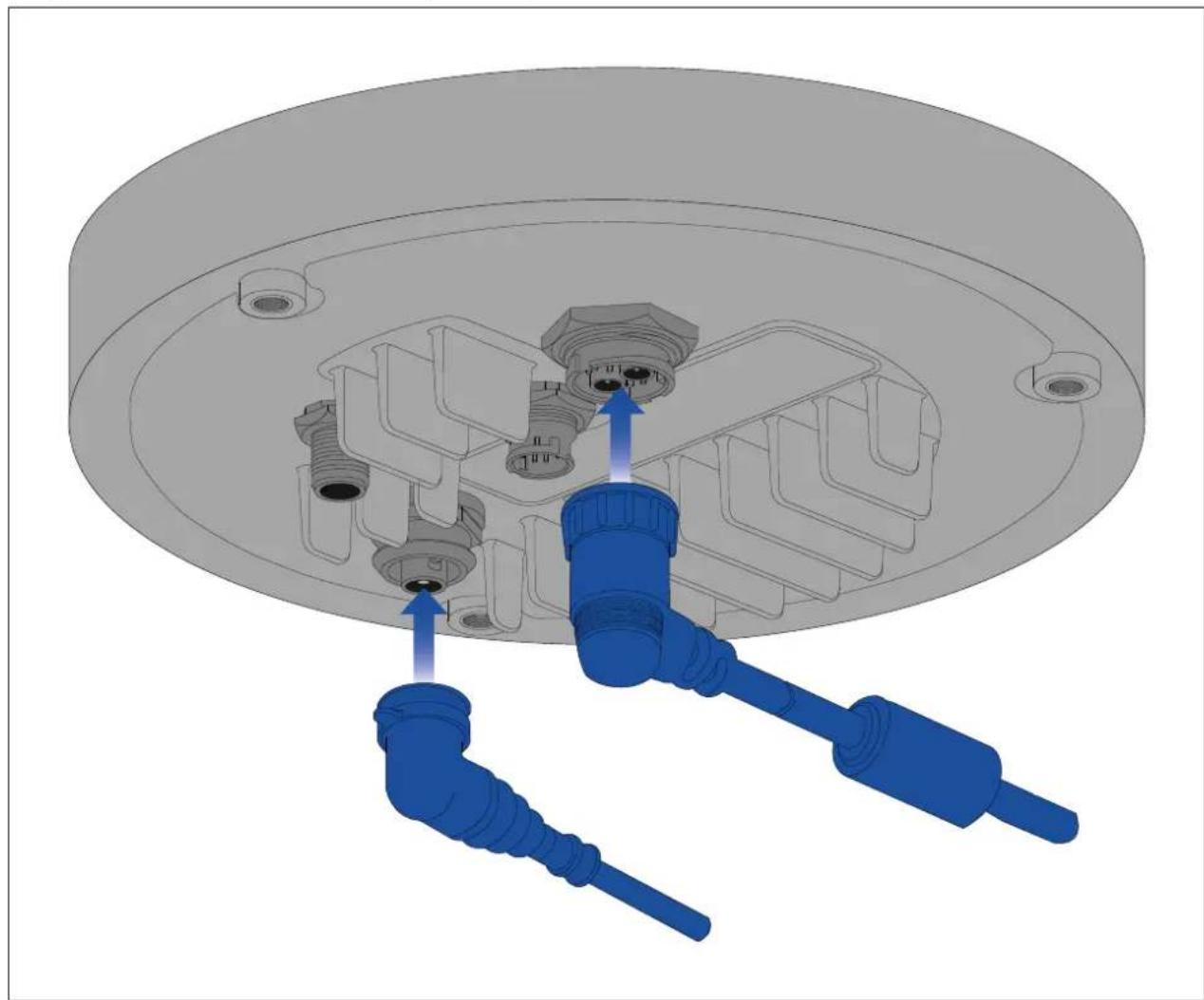
natural_image
3D mechanical assembly diagram showing a component with blue connectors and internal parts (no text or symbols)4.3Videoconnections
Thecamera'svideooutputcanbedistributedtoupto4devices,simultaneously.
Furthermore, with the dual payload camera variants you can use any of the 4 different camera output display different combinations thermal visiblght video feed, simultaneously. Forexample, you can view the thermal video feed via the HD-SDI video output, and the visible light video feed at the same time via a laptop connected to the camera's RayNet (Ethernet) connector.
Note: Thereisalsoaspecificscenariowhereitispossibletodistributevideotomorethan 4devicessimultaneously.WithaRaymarineAxiomPromultifunctiondisplay(MFD),you canonnedheamera'analogompositevideoutputMFD'analogompositevideinputtheshare/repeathatidefeerealtimevethRayNetetworko multipleadditionalLightHouse3RaymarineMFDsonthesamenetwork.Thiscanallbe outputsimultaneouslywiththe3otherdigitalvideooutputsdescribedbelow.
The4differentvideooutputsare:
2digitalvideoutputsithRayNetEthernetConnectorstreamedveEthernet/IP:
H264-encodedigitalvideethistreametaONVI(Profile)-compatible video-capabledisplay,videodistributionunit,videomultiplexer,orRaymarineLightHouse 3multifunctiondisplay(MFD).
-MPEG-encodeddigitalvideo—thisisstreamedtoawebbrowseronaPC/laptop/tabletconnectedtothecamera'sRayNet(Ethernet)connector.
- 1xdigitalvideofeed, outputviatheHD-SDIconnector.
- 1xanalogvideofeed, outputviathecompositevideoBNCconnectoronthecamera's powercable.
| Connector | Videoformat | |
| 1 | CompositevideoBNCconnectoron camera'spowercable | Analogvideo. |
| 2 | RayNet(Ethernet) | •H264-encodedIPdigitalvideo(ONVIF ProfileS).•MPEG-encodedIPdigitalvideo(via webbrowseronly). |
| 3 | HD-SDIDigitalvideo,HD-SDIformat | (SMPTE-292M). |
Note: It is also possible to connect to an HDMI-capable display or other videodevice, via suitable third-party HD-SDI to HDMI converter. Contact your dealer or retailer for suitable devices and cables.
Note:ONVIFprofileshelpyoutodeterminewhichIPdigitalvideodevicesarecompatible withoneanother.FormoreinformationonONVIFprofiles,referto:www.onvif.org/profiles/
Switchingbetweenthermalandvisiblelight(daylight)camerafeeds(dualpayload cameravariantsonly)
Thedualpayloadcameravariantshaveseparatethermalandvisiblelight(daylight)video feeds, and you can switch between these two different video feeds at any time using a JCU, a web browser, or a Raymarine Light House 3MFD.
Videoandnetworkcables
Arangeofcablesissuppledwiththecameratocovertypicalconnectionscenarios.Y ou mayneedtopurchaseadditionalcablestocompleteyourinstallation.
| ConnectorSuitablecables | |
| CompositevideoBNCconnectoron camera'spowercable | UsethesuppliedBNC-to-BNCvideocable(3m/9.8 ft.),ifnotusingotherwisefortheHD-SDIconnection.Alternatively,obtaina75-ohmcoaxvideocable terminatedinBNCconnectorsatbothends.(The BNCconnectoronthecamera'spowercableisa femaleconnector). |
| RayNet(Ethernet)T oconnecttoadevic | ewithanRJ45socket:UsethesuppliedRayNet-to-RJ45adaptercable(120 mm/4.7in.).Longeradaptercablesareavailable separately—referto12.3RayNettoRJ45adapter cablesT oconnecttoaRaymarineMFDrRayNetnetwork switch:ObtainasuitablelengthRayNet-to-RayNet cable(availableseparately—referto12.4RayNetto RayNetcablesandconnectors). |
| BNC-SDeocable(3m/9.8 | ft.).Ifalongercableisrequired,obtaina75-ohm coaxvideocableterminatedinBNCconnectorsat bothends.(TheBNCconnectoronthecamerais afemaleconnector). |
| Note:ItisalsopossibletoconnecttoanHDMI-capabledisplayorothervideodevice, viaasuitablethird-partyHD-SDItoHDMlconverter.Contactyourdealerorretailerfor suitabledevicesandcables. | |
4.4NMEA0183connection
NMEA0183devicescanbeconnectedtoyourcamerausingtheNMEA0183wireson thesuppliedPower/Video/NMEA0183cable.
2NMEA0183portsareavailable:
- Port1: Inputandoutput: 4,800baudrateonly.
- Port2:Inputonly:4,800baudrateonly.
Note:
- ForPort1, both the input and output communicate at the same baud rate. For example, if you have one NMEA0183 device connected to Port1 INPUT, and another NMEA0183 device connected to Port1 OUTPUT, both NMEA devices must us these same baud rate.
Upto4devicescanbeconnectedtothecamera'soutputport, andupto2devicesto thecamera'sinputports.
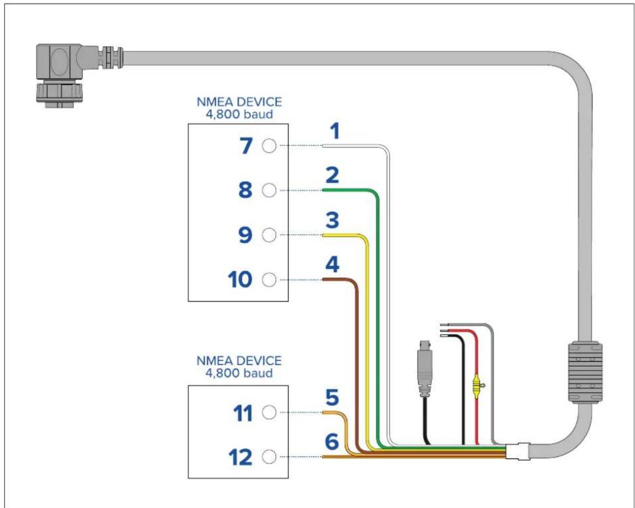
| ItemDevice | CablecolorPort | Input/output | Positive(+)/negative(-) | ||
| 1 | Camera | White | 1 | InputPositive | |
| 2 | Green | 1 | InputNegative | ||
| 3 | Yellow | 1 | Output | Positive | |
| 4 | Brown | 1 | Output | Negative | |
| 5 | Orange/White | 2 | InputPositive | ||
| 6 | Orange/Green | 2 | InputNegative | ||
| 7 * | NMEAdevice | * | Output | Positive | |
| 8 * | * | Output | Negative | ||
| 9 | **InputPositive | ||||
| 10 | **InputNegative | ||||
| 11 * | NMEAdevice | * | Output | Positive | |
| 12 * | * | Output | Negative |
Note:
*RefertoinstructionsprovidedwithyourNMEA0183deviceforconnectiondetails.
4.5T ypicalsystems
The cameracanbeconnectedtovarietyofdigitaloranalogvideosystems,andcontrolled viaaJCU,awebbrowser,aRaymarinemultifunctiondisplay(MFD),oranycombination ofthese.
Note:
- Forinformationonhowtoconnecttheproduct, refertothep.45—Connectionsoverview
- Forinformationonavailablecablesandaccessories, refertothe p.101—Sparesandaccessories
BasicWebrowsystem:ocaponnedcameralirectlyalP-capabledevice, suchasalaptorPC,usingthesuppliedRayNetcableandRayNet-to-RJ45adapter cable:ocapontrdcamerthroughtheseinterfaceaccessibleiaevrowser.
BasidigitalidedisplaysystemwithCUy ouaponnedheamerdirectlya primarydigitalvideodisplayviathecamera'sHD-SDloutputandthesuppliedBNCable, orviaHDMIusingasuitablethird-partyvideoconverter(availableseparatelyfroman electronicsretailoutlet).
BasianalogidedisplaysystemwithCU?ouaponnedheameraldirectlya primaryanalogvideodisplayviathecamera'scompositeanalogvideooutputusingthe BNCconnectoronthecamera'spowercable.
BasilWebrowsystemwithCU: odaponnedproductP-capable device, such as alaptorPC, viaanEthernetswitch (using the supplied RayNetcable and RayNet-to-RJ45 adaptercable), and an additional Ethernetcable. You can control the camerathrough the user interface accessible via a webbrowser, or with a JCU unit, also connected to the Ethernet switch.
BasiRaymarineightHousmultifunctiodisplayMFDsystem:ouanconnect theproductdirectlytoaRaymarineLightHouse3MFDusingthesuppliedRayNetcable. YoucancontrolthecameradirectlyusingtheMFD.Foramoreflexiblesystem,youcan installaRayNetswitchbetweenthecameraandtheMFD,andaddaJCUunit(also connectedtotheRayNetswitch)toprovideadditionalcameracontrols.
- Complexsystemwithmultiplecameras,MFDs,andJCUs:WithsufficientRayNetor Ethernetportsavailableoninstalledswitches,andappropriateRayNetandEthernetcables, youcanconnectmultiplecamerasMFDsandCUtogetheformintegratedsystem. YoucanuseanyJCUorMFDtocontrolandmonitoranycamera.
4.6 Network connections
YourcamerahasasingleRayNetnetworkconnector. Thisconnectsthecameratoyour vessel'swiderIPnetwork. Thiscouldbeanexistingthird-partyEthernetnetwork,ora dedicatedRaymarineRayNetnetwork.
The detail of the network connections between the camera, video display (web browser, videomonitor, or Light House 3 Ray marinemultifunction display), control unit (fore example, a JCU-2 controller) and therest of your installation dependent:
- Howyouwanttocontrolthecamera(forexample,withawebbrowser,aLightHouse3 Raymarinemultifunctiondisplay,aJCUcontroller,oracombination).
Howowartview theamera's Ridefee (for example, laptop, Ovia LightHouse3Raymarinemultifunctiondisplay, oracombination).
- theequipmentalreadyinstalledonyourvessel(forexample,networkswitcheswithfree ports,orothercameras).
The following sections show some possible network connections, starting with abasicsystem with a single cameradirectly connected to web browser, and finishing with a more complex multi-camera, multi-display, multi-JCUsystem.
Non-RayNetsystems
Youcaninstallyourcameraonavesselthatdoesn'thaveaRayNetnetworkorLightHouse3Raymarinemultifunctiondisplay(MFD)installed.
The following examples show possiblenetworkconnections for:
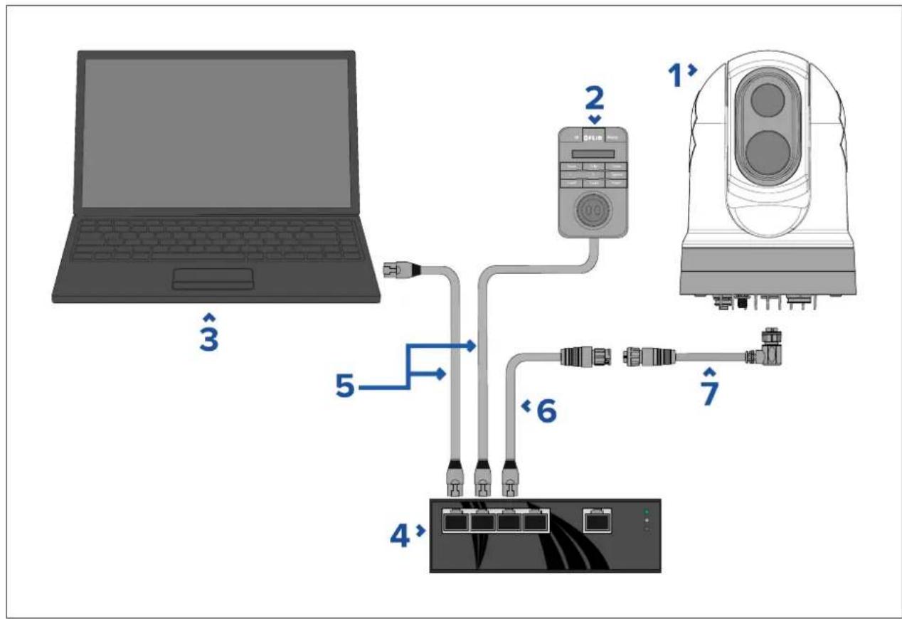
- Asingle-camerasystemwiththecameraconnecteddirectlytoalaptoporotherdevice runningawebbrowser(forcameracontrol,andviewingthecamera'sIPvideofeed).
- Asingle-camerasystemcomprisingalaptoporotherdevicerunningawebbrowser(for cameracontrol,andviewingthecamera'sIPvideofeed),anEthernetnetworkswitchwith PoE,andanoptionalJCU(availableseparately)foradditionalcameracontrol
- Asingle-camerasystemcomprisingadigitalvideomonitorconnectedviathecamera's HD-SDIvideofeed,anEthernetnetworkswitchwithPoE,andaJCU(availableseparately) forcameracontrol.
- Asingle-camerasystemcomprisingadigitalvideomonitorconnectedviathecamera's HD-SDIvideofeedandanHDMIconvertertoallowconnectionviaHDMI.AlsoanEthernet networkswitchwithPoE,andaJCU(availableseparately)forcameracontrol.
- Asingle-camerasystemcomprisingananalogvideomonitorconnectedviathecamera's compositevideofeed(connectedviathepowercable),anEthernetnetworkswitchwith PoE,andaJCU(availableseparately)forcameracontrol.
Single-camerasystemwithdirectconnectiontowebbrowser
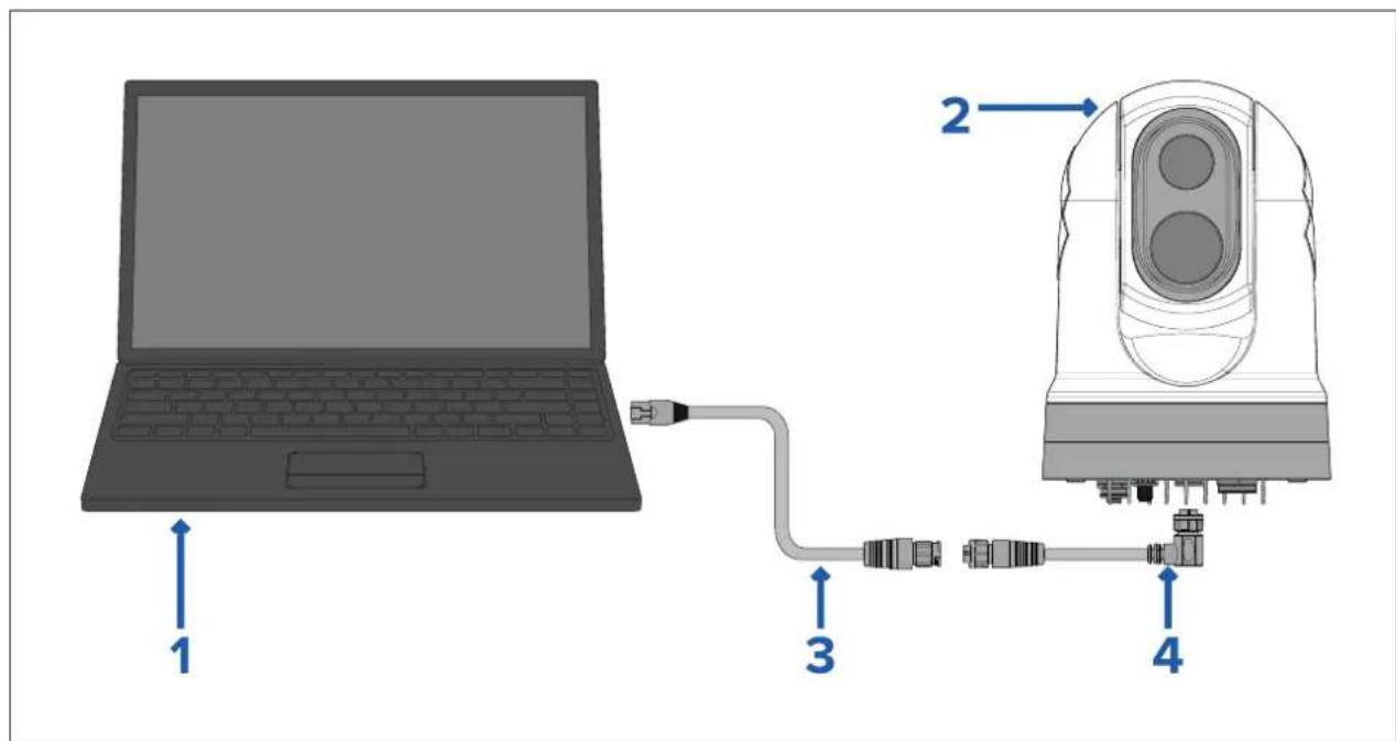
Note: Powerconnections are not shown in this illustration. The camera and the other devices shown require their own dedicated power connection.
| Description | |
| 1 | Laptop(orotherEthernet-connecteddevicerunningawebbrowser), availableseparatelyfromthird-partyretailers |
| 2 | M300Seriescamera |
| 3 | RayNet-to-RJ45adaptercable(120mm/4.7in.)(suppliedwithcamera) |
| 4 | RightangledRayNet-to-RayNetcable(3m/9.8ft)(suppliedwithcamera) |
Single-camerasystemwithwebbrowserandanoptionalJCU
flowchart
graph TD
    A["Laptop"] -->|3| B["Network Port"]
    B -->|5| C["4 Ethernet"]
    B -->|6| D["2 OFF/Control Unit"]
    D -->|7| E["Electronic Device"]
    style A fill:#99ccff,stroke:#333
    style B fill:#cccccc,stroke:#333
    style C fill:#ffffff,stroke:#333
    style D fill:#ffffff,stroke:#333
    style E fill:#ffffff,stroke:#333
| Note:Powerconnectionsarenotshowninthisillustration.Thecameraandtheother deviceshownrequiretheirowndedicatedpowerconnection. | |
| Description | |
| 1 | M300Seriescamera |
| 2 | Joystickcontrolunit(JCU-2),availableseparately |
| 3 | Laptop(orotherEthernet-connecteddevicerunningawebbrowser) |
| 4 | EthernetnetworkswitchwithPoE |
| 5 | RJ45-to-RJ45Ethernetcable |
| 6 | RayNet-to-RJ45adaptercable(120mm/4.7in.)(suppliedwithcamera) |
| 7 | RightangledRayNet-to-RayNetcable(3m/9.8ft)(suppliedwithcamera) |
Single-camerasystemwithdigitalvideo(HD-SDI)monitorandJCU
Forthissystem, adevicerunningawebbrowserisnotrequired. Thecamera'svideofeedis routedthroughthecamera'sHD-SDIvideoconnectiontoadigitalvideomonitor. Camera controlisprovidedbyaJCU(availableseparately).
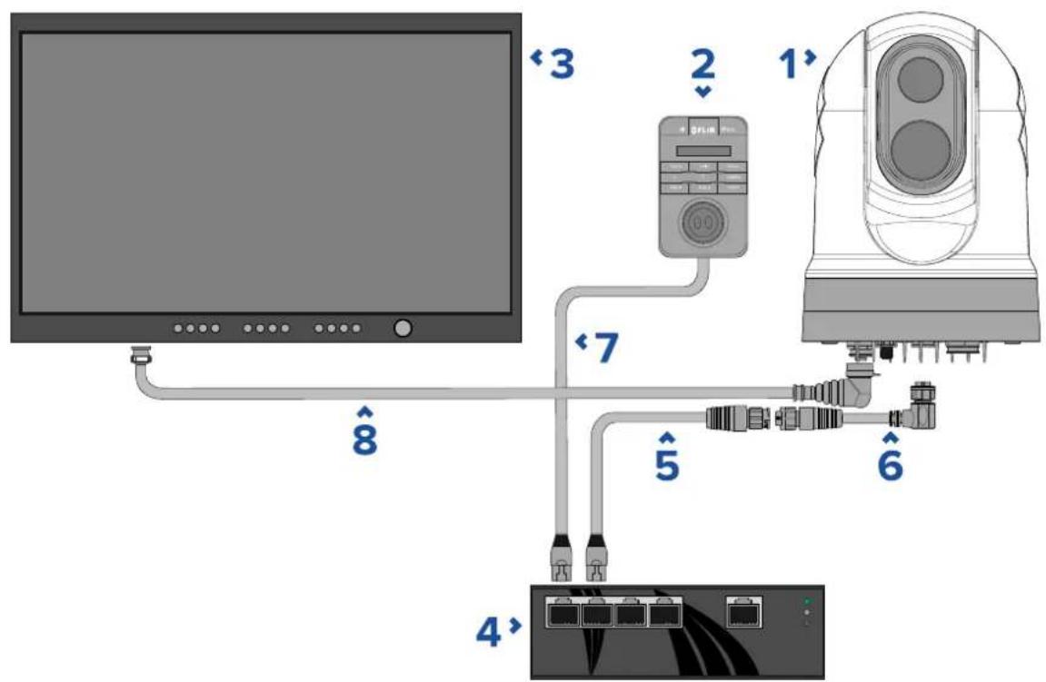
Note: Powerconnections are not shown in this illustration. The camera and the other devices shown require their own dedicated power connection.
| Description | |
| 1 | M300Seriescamera |
| 2 | Joystickcontrolunit(JCU-2),availableseparately |
| 3 | Digitalvideo(HD-SDI)monitor,availableseparatelyfromthird-partyretailers |
| 4 | EthernetnetworkswitchwithPoE,availableseparately |
| 5 | RayNet-to-RJ45adaptercable(120mm/4.7in.)(suppliedwithcamera) |
| 6 | RayNet-to-RayNetcable,availableseparately |
| 7 | RJ45–to-RJ45cable,availableseparately |
| 8 | HD-SDIvideocable(BNCconnectors)(3m/9.8ft.)(suppliedwith camera) |
Single-camerasystemwithdigitalvideo(HDMI)monitorandJCU
Forthissystem, adevicerunningawebbrowserisnotrequired. Thecamera'svideo feedisroutedthroughthecamera'sHD-SDIvideoconnectionviaathird-partyHD-SDIto HDMIvideoconverter(notsupplied)toadigitalvideomonitor.Cameracontrolisprovided byaJCU(availableseparately).
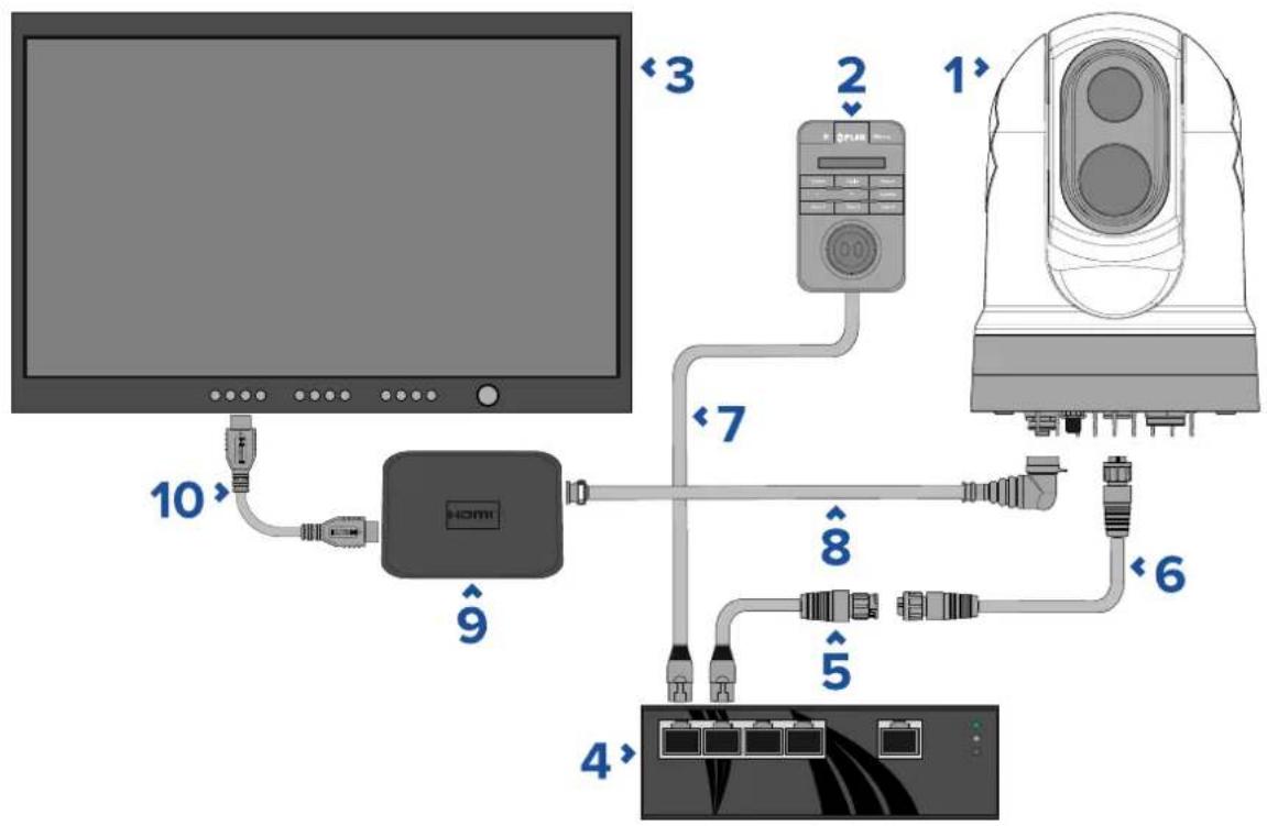
Note: Powerconnections are not shown in this illustration. The camera and the other devices shown require their own dedicated power connection.
| Description | |
| 1 | M300Seriescamera |
| 2 | Joystickcontrolunit(JCU-2),availableseparately |
| 3 | Digitalvideo(HD-SDI)monitor,availableseparatelyfromthird-partyretailers |
| 4 | EthernetnetworkswitchwithPoE,availableseparately |
| 5 | RayNet-to-RJ45adaptercable(120mm/4.7in.)(suppliedwithcamera) |
| 6 | RayNet-to-RayNetcable,availableseparately |
| 7 | RJ45–to-RJ45cable,availableseparately |
| 8 | HD-SDIvideocable(BNCconnectors)(3m/9.8ft.)(suppliedwithcamera) |
| 9 | HD-SDItoHDMIvideoconverter,availableseparatelyfromthird-partyretailers |
| 10 | HDMlcable,availableseparatelyfromthird-partyretailers |
Single-camerasystemwithanalogvideomonitorandJCU
Forthissystem, adevicerunningawebbrowserisnotrequired. Thecamera'svideofeedis routed through the powercable's composite analog video connection to an analog video monitor. Camera control is provided by a JCU (available separately).
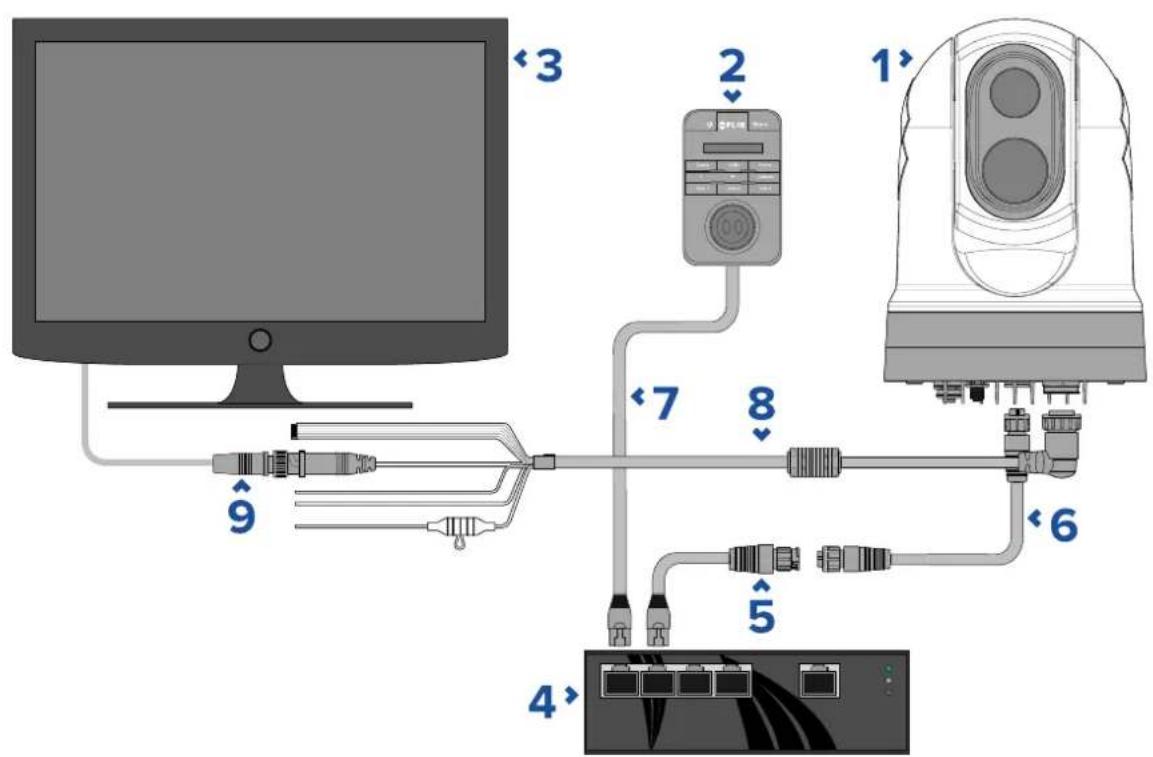
Note: Powerconnections are not shown in this illustration. The camera and the other devices shown require their own dedicated power connection.
| Description | |
| 1 | M300Seriescamera |
| 2 | Joystickcontrolunit(JCU-2),availableseparately |
| 3 | Analogvideomonitor,availableseparatelyfromthird-partyretailers |
| 4 | EthernetnetworkswitchwithPoE,availableseparately |
| 5 | RayNet-to-RJ45adaptercable(120mm/4.7in.)(suppliedwithcamera) |
| 6 | RayNet-to-RayNetcable,availableseparately |
| 7 | RJ45–to-RJ45cable,availableseparately |
| 8 | Camera'spowercable(3m/9.8ft.)(suppliedwithcamera) |
| 9 | BNC-to-BNCvideocable.IfyouarenotusingthesuppliedBNC cable(3m/9.8ft.)fortheHD-SDIconnection,youcanuseitfor thiscompositeanalogconnection.Otherwise,obtainasuitablecable, separatelyfromthird-partyretailers. |
RayNetsystemswithRaymarineLightHouse3multifunctiondisplays (MFDs)
M300-SeriescamerasarecompatiblewithRaymarineLightHouse3multifunctiondisplays (MFDs)andexistingRayNetnetworks.
The following examples show possiblenetwork connections for:
- asingle-camerasystemcomprisingaRaymarineLightHouse3MFD(forcameracontrol, andviewingthecamera'sIPvideofeed),aRayNetnetworkswitch,aJCU(available separately)foradditionalcameracontrol,andaPoweroverEthernet(PoE)Injector.
- amulti-camerasystemcomprisinganHD-SDIvideomonitor,2RaymarineMFDs(available separately),aRayNetnetworkswitch(availableseparately),2JCUs(availableseparately),
aPoweroverEthernet(PoE)Injector(availableseparately), andawebbrowser(laptop)(availableseparately) for additionalcameracontrol.
Single-camerasystemwithRaymarineMFDandJCU

Note: Powerconnections are not shown in this illustration. The camera and the other devices shown require their own dedicated power connection.
| 1 | M300Seriescamera |
| 2 | Joystickcontrolunit(JCU-2),availableseparately |
| 3 | RaymarineMFD,availableseparately |
| 4 | RayNetnetworkswitch,availableseparately |
| 5 | Right-angledRayNet-to-RayNetcable,(suppliedwithcamera) |
| 6 | RJ45–to-RJ45cable,availableseparately |
| 7 | PoEinjector(providespowertoJCU-2),availableseparately |
| 8 | RayNet-to-RJ45adaptercable,(120mm/4.7in.versionsuppliedwithcamera;otherlengthsavailableseparately) |
Multi-camerasystemwithdigitalvideomonitor,2RaymarineMFDs,2JCUs,anda webbrowser
flowchart
graph TD
    A["Laptop <1"] --> B["Monitor 2"]
    B --> C["FRIR 3"]
    C --> D["Monitor 4"]
    D --> E["FRIR 5"]
    E --> F["Monitor 6"]
    F --> G["FLIR 7"]
    G --> H["Monitor 7"]
    H --> I["FLIR 8"]
    I --> J["Monitor 9"]
    J --> K["FLIR 10"]
    K --> L["Monitor 11"]
    L --> M["FLIR 11"]
    M --> N["Monitor 12"]
    N --> O["FLIR 12"]
    O --> P["Monitor 13"]
    P --> Q["FLIR 13"]
    Q --> R["Monitor 14"]
    R --> S["FLIR 14"]
    S --> T["Monitor 15"]
    T --> U["FLIR 15"]
    U --> V["Monitor 16"]
    V --> W["FLIR 16"]
    W --> X["Monitor 17"]
    X --> Y["FLIR 17"]
| Note:Powerconnectionsarenotshowninthisillustration. Thecameraandtheother deviceshownrequiretheirowndedicatedpowerconnection. |
| Description | |
| 1 | Laptop(orotherEthernet-connecteddevicerunningawebbrowser),availableseparatelyfromthird-partyretailers |
| 2 | Digitalvideomonitor,availableseparatelyfromthird-partyretailers |
| 3 | M300Seriescamera |
| 4 | Joystickcontrolunit(JCU-2),availableseparately |
| 5 | RaymarineMFD,availableseparately |
| 6 | RayNetnetworkswitch,availableseparately |
| 7 | RayNet-to-RayNetcable,availableseparately |
| 8 | RightangledRayNet-to-RayNetcable(3m/9.8ft)(suppliedwithcamera) |
| 9 | RJ45–to-RJ45cable,availableseparately |
| 10 | PoEinjector(providespowertoJCU-2),availableseparately |
| 11 | RayNet-to-RJ45adaptercable,(120mm/4.72in.versionsuppliedwithcamera;otherlengthsavailableseparately) |
| 12 | HD-SDIvideocable(BNCconnectors)(3m/9.8ft.)(suppliedwithcamera) |
4.7 Powerconnection
Powermustbesuppliedtothecamerafromanappropriatepowersource.
Powerconnectionrequirements
•12or24Vdcnominalsupplyvoltage
•Isolatedpowersupply
- Connectedviaanappropriately-ratedthermalbreakerorfusedswitch(refertoInlinefuse andthermalbreakerratings).
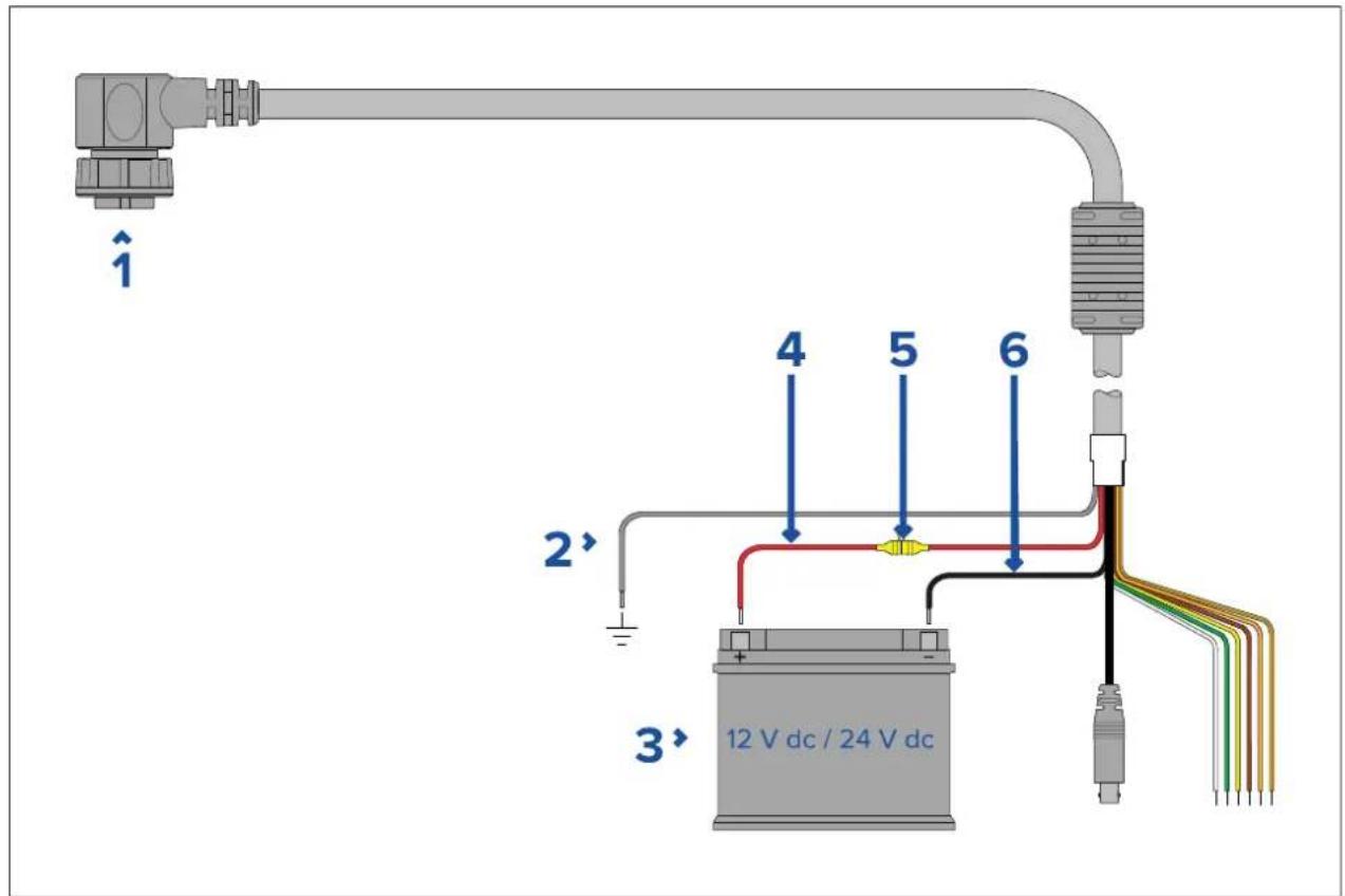
| Description | Connectsto: | |
| 1 | Powercable.Product'spowerconnector. | |
| 2 | Drain/ground(thinblackwire) | Vessel'sRFground,ornegativebattery terminal. |
| 3 | Connectionto12V/24Vpowersupply. | Vessel'spowersupply. |
| 4 | Redcable(positive) | Powersupply'spositiveterminal |
| 5 | InlinefuseWaterproofuseholdercontaininga | suitably-ratedinlinefuse(refertoInline fuseandthermalbreakerratings). |
| 6 | Blackcable(thickblackwire)(negative) | Powersupply'snegativeterminal |
Powerdistribution
Recommendationsandbestpractice.
•Theproductissuppliedwithapowercable,eitherasaseparateitemoracaptiveable permanentlyattachedtotheproduct.Onlyusethepowercablesuppliedwiththeproduct.DoNOTuseapowercabledesignedfor,orsuppliedwith,adifferentproduct.
Refet the Power connection section for more information how identify the wire in your product's powercable, and where to connect them.
- See below form more information on implementation for some common power distribution scenarios:
Important:
- Whenplanningandwiring, takeintoconsiderationotherproductsinyoursystem, some of which (e.g.sonarmodules) may placelargepowerdemandpeaksonthevessel's electricalsystem, which may impact the voltage available to other products during the peaks.
•Theinformationprovidedbelowisforguidanceonly,tohelpprotectyourproduct.It coverscommonvesselpowerarrangements,butdoesNOTcovereveryscenario.Ifyou areunsurehowtoprovidethecorrectlevelofprotection,pleaseconsultanaauthorized dealerorasuitablyqualifiedprofessionalmarineelectrician.
Implementation—connectiontodistributionpanel(Recommended)
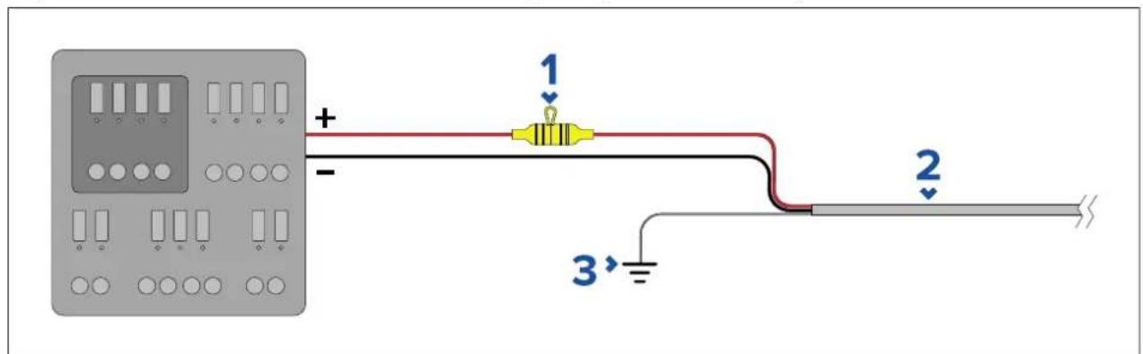
| 1 | Waterproofuseholdercontainingasuitably-ratedinlinefusemust befitted.Forsuitablefuserating,referto:In-linefuseandthermal breakerratings. |
| 2 | Productpowercable. |
| 3 | Drainwireconnectionpoint. |
- It is recommended that the supplied power cable is connected to a suitable breaker or switch on the vessel's distribution panel or factory-fitted power distribution point.
- Thedistributionpointshouldbefedfromthevessel'sprimarypowersourceby8AWG (8.36mm ^2 )cable.
- Ideally, allequipments should bewired to individuals suitably-rated thermal breakers or fuses, with appropriate circuit protection. Where this is not possible and more than 1 item of equipment shares a breaker, use individual in-line fuses for each power circuit to provide the necessary protection.
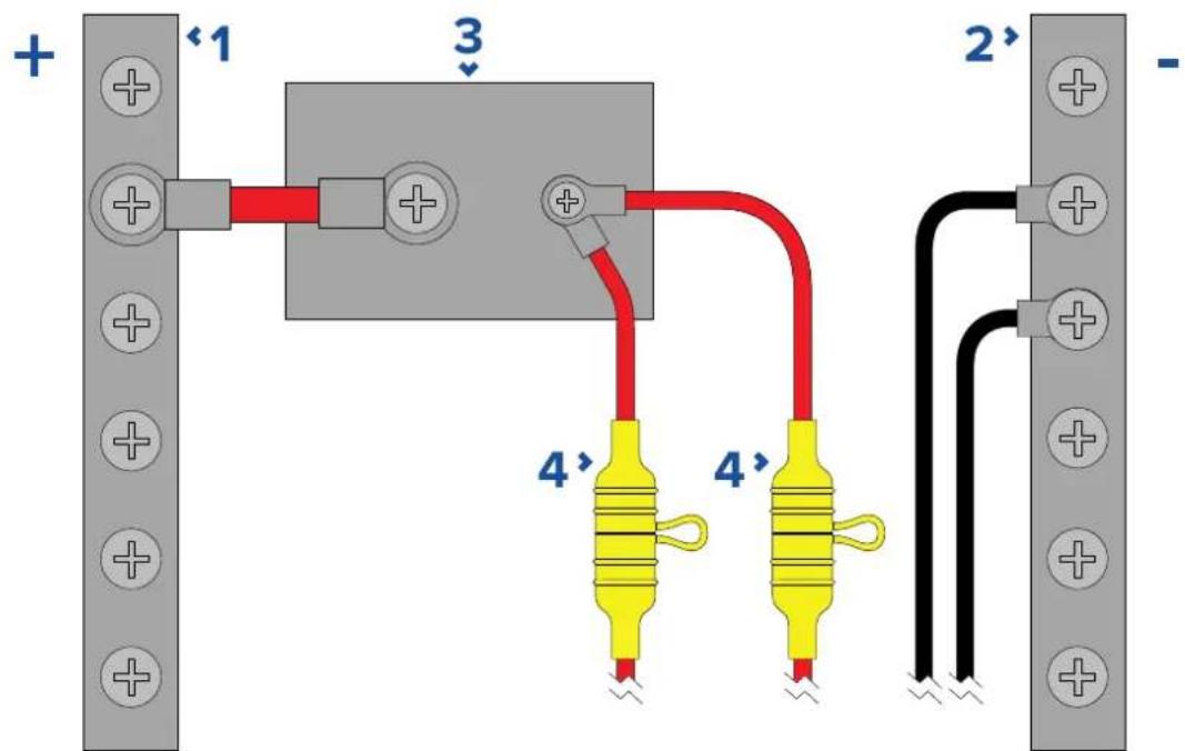
| 1 | Positive(+)bar |
| 2 | Negative(-)bar |
| 3 | Circuitbreaker |
| 4 | Waterproofuseholdercontainingasuitably-ratedinlinefusemust befitted.Forsuitablefuserating,referto:In-linefuseandthermal breakerratings. |
Important:
Observetherecommendedfuse/breakerratingsprovidedintheproduct'sdocumentation, howeverbeawarethatthesuitablefuse/breakerratingisdependentonthenumberof devicesbeingconnected.
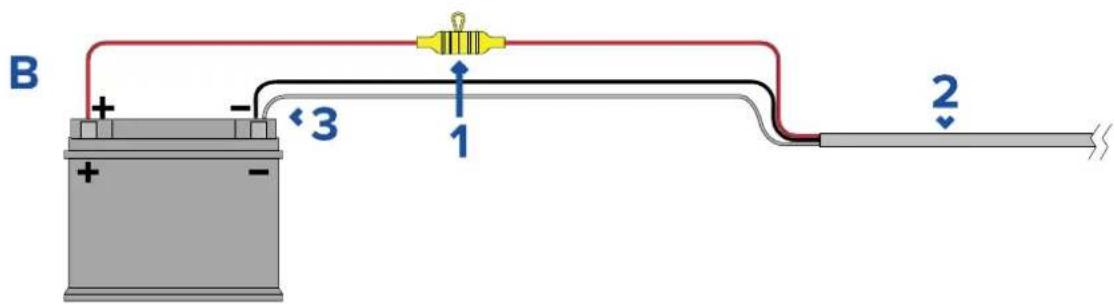
Implementation—directconnectiontobattery
- Whereconnectiontoapowerdistributionpanelisnotpossible, the powercables supplied with your product maybe connected directly to the vessel's battery, via asuitably rated fuseorbreaker.
- ThepowercablesuppliedwithyourproductmayNOTincludeaseparatedrainwire.Ifthis isthecase,onlythepowercable'sredandblackwiresneedtobeconnected.
- If the powercable is not supplied with a fitted inline fuse, you must fit suitably rated fuse or breaker between thered wire and the battery's positiveterminal.
•Refertotheinlinefuseratingsprovidedintheproduct'sdocumentation. - If you need to extend the length of the powercables supplied with your product, ensure you observe dedicated powercable extensions advice provided in the product's documentation.
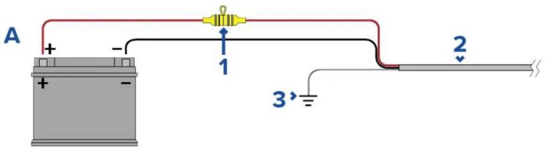
| 1 | Waterproofuseholdercontainingasuitably-ratedinlinefusemust befitted.Forsuitablefuserating,referto:In-linefuseandthermal breakerratings. |
| 2 | Productpowercable. |
| 3 | Drainwireconnectionpoint. |
BatteryconnectionscenarioA:
SuitableforavesselwithacommonRFgroundpoint.Inthisscenario,ifyourproduct's powercableissuppliedwithaseparatedrainwirethenitshouldbeconnectedtothe vessel'scommongroundpoint.
BatteryconnectionsscenarioB:
Suitableforavesselwithoutacommongroundingpoint.Inthiscase,ifyourproduct's powercableissuppliedwithaseparatedrainwirethenitshouldbeconnecteddirectly tothebattery'snegativeterminal.
Powercableextension
If you need to extend the length of the power cables supplied with your product, ensure you observe the following advice:
- The powercableforeachunitinyoursystemshouldberunasaseparate, singlelength of2-wirecablefromtheunittothevessel'sbatteryordistributionpanel.
- Ensure that the extension cable is sufficient, for the supply voltage and the total load of the device and the length of the cabler run. Referto the following table for typical minimum power cable wire gauges.
| Cablelengthinmeters (feet) | WiregaugeinAWG(mm 2) for12Vsupply | WiregaugeinAWG(mm 2) for24Vsupply |
| <8(<25)16(1.31mm) | 2)18(0.82mm) | 2) |
| 16(50)14(2.08mm) | 2)18(0.82mm) | 2) |
| 24(75)12(3.31mm) | 2)16(1.31mm) | 2) |
| >32(>100)10(5.26mm) | 2)16(1.31mm) | 2) |
Important:
Beawarethatsomeproductsinyoursystem(suchassonarmodules)cancreatevoltage peaksatcertaintimes,whichmayimpactthevoltageavailabletootherproductsduring thepeaks.
Important: To ensure powercables (including any extension) are of sufficient gauge, ensure that continuous minimum voltage of 0.1V each be able where it enter the product's power connector, even with a fully flat battery at 1 Vdc. (Donotassumethataflat battery is at 0 Vdc. Duetothed discharge profile and internal chemistry of batteries, the current dropsmuch faster than the voltage. A "fully flat" battery still shows a positive voltage, even if it doesn't have enough current topowery our device.)
Grounding
Ensure that you observe any additional grounding advice provided in the product's documentation.
Moreinformation
It is recommended that best practice is observed in all vesse electrical installations, as detailed in the following standards:
•BMEACodeofPracticeforElectricalandElectronicInstallationsinBoats
•NMEA0400InstallationStandard
•ABYCE-11AC&DCElectricalSystemsonBoats
•ABYCA-31BatterychargersandInverters
•ABYCTE-4LightningProtection
In-linefuseandthermalbreakerratings
The following in-line fuse and thermal breakerratings apply to your product:
| In-linefuseratingThermalbreakerrating | |
| 15Aslowblow | 15A(ifonlyconnectingonedevice) |
Note:
- Thesuitablefuseratingforthethermalbreakerisdependentonthenumberofdevices youareconnecting.IfindoubtconsultanaauthorizedFLIRdealer.
- Yourproduct'spowercablemayhaveafittedin-linefuse,ifnotthenyoucanaddan in-linefusetothepositivewireofyourproduct'spowerconnection.
Grounding—Dedicateddrainwire
The powercables supplied with this product includes a dedicated shield (drain) wire for connection to avessel's RF groundpoint.
It is important that an effective RF ground disconnected to the system. As single ground point should be used for all equipment. The unit can be grounded by connecting the shield (drain) wire of the power cable to the vessel's RF ground point. On vessels without an RF ground system, the shield (drain) wire should be connected directly to the negative battery terminal.
Thedcpowersystemshouldbeeither:
- Negativegrounded, with thenegative battery terminal connected to the vessel's ground.
- Floating, with neither battery terminal connected to the vessel's ground

Warning: Positivegroundsystems
Donotconnectthisunittoasystemwhichhaspositivegrounding.
Chapter5: Camera control options and status icons
Chaptercontents
•5.1 Cameracontroloptionsonpage66
•5.2Cameraimageonpage66
•5.3Cameracontrolonpage73
5.1 Cameracontroloptions
Thereareanumberofdifferentwaysofcontrollingthecameraremotely.
- Viaawebbrowser—WiththecameraconnectedtoalaportabletviaEthernet,youcanusethecamera'swebbrowsertoviewandcontrolthecameraremotely.
- ViaaJCU—WiththeJCUconnectedtothecameraviaanetworkswitch,youcanuse theJCU'sphysicalcontrolstocontrolthecameraremotely.
- ViaaRaymarineLightHouse3MFD—WiththecameraconnectedtotheMFDor theMFD'snetworkviaRayNet(Ethernet),youcanusetheMFD'sVideoapptoview andcontrolthecameraremotely.
Note: It is also possible to switch the thermal/visible light video of feed of dual payload camera variants using any of the control options listed above.
5.2Cameraimage
TheM300cameraoutputsanIPdigitalvideofeedwhichcanbedisplayedonavideo monitor,awebbrowser,oraRaymarineLightHouse3multifunctiondisplay(MFD).
Dependingonchosencameramodel, theIPdigitalvideofeedcomprises:
•Visiblelight(daylight)image
•Thermalimage
•Statusiconsoverlaidonthevideoimage
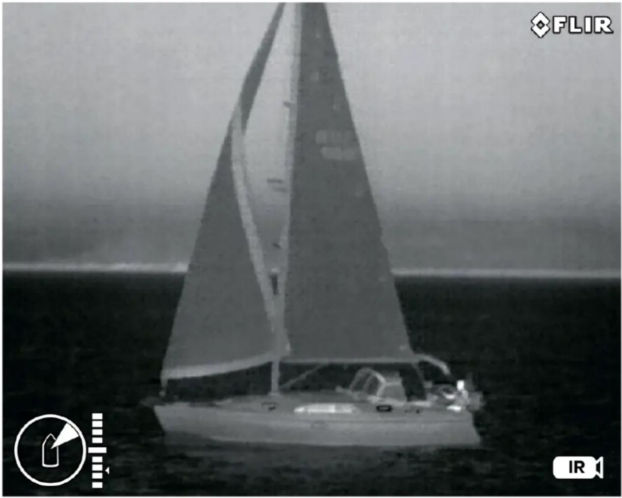
ThermalCamera
Y oushouldtaketimetofamiliarizeyourselfwiththethermalimage.Thiswillhelpyouto getthemostoutofoursystem:
- Considereveryobjectyouviewintermsofhowitwilllook"thermally"asopposedtohowitlookstoyoureye.Forexamplelookforchangescausedbytheheatingeffectofthesun.Theseareparticularlyevidentrightaftersunset.
- Experimentwithdifferentpalettesandscenepresets.
- Experimentbylookingforhotobjects(suchaspeople)comparedtothecoldersurroundings.
- Experimentwiththecameraford daytimeviewing. The cameracanprovideimproved daytimeviewinginenvirronmentswheretraditionalvideocameraperformancesuffers,such asinshadowsorbacklitsscenes.
natural_image
Black-and-white photo of a sailboat on the ocean with visible hull and sail, no text or symbols present.Camerastatusicons
Thecameraimageincludesiconstoshowthecurrentstatusofthecamera.
| Note:IconareoloredtheWhiteHotrforallotherpalettes. | ||
| IconName | Description | |
 | ThermalCameraIndicatestheThermalC | camerafeedisactive. |
 | Visible/DaylightCameraIndicatestheV | visible/DaylightCamerafeedisactive. |
| IconName | Description | |
 | Azimuth(Position) | Showstheazimuth(ordirection)of thecamerarelativetothevessel. Thetriangleshowstheapproximate camerafieldofview(FOV). |
 | Elevation(Tilt) | Showstheverticaltiltofthe camera. Thetriangleshowsthe approximatecameraposition. |
Focus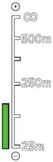 | FocusScaleShownwhenautofocusisinvoked toindicatetheprogressofthe operation. | |
 | HomeIndicatesthecameraisinthehome | position; theiconflasheswhena newhomepositionisset. |
 | LockZoom | Lockthezoomofcameratothe activepayload, wheneverpossible. |
 | MirroredViewIndicatesthecamerafeedis | reversedagainsttheverticalaxis. |
 | Polarity | Indicatesachangeinimagepolarity. |
 | ColorPalette | Indicatesachangeinimagecolor palette. |
 | NMEABWSMessage | ReceivingNMEA messagesusing BearingandDistancetoWaypoint, GreatCircle(BWC)sentenceformat hasbeenenabled;thisisalso knownasslewtowaypoint. |
 | NMEARSD | ReceivingNMEA messagesusing theRadarSystemData(RSD) sentenceformathasbeenenabled; thisisalsoknownasradarcursor tracking. |
 | NMEATTMReceivingNMEA messagesusing theNMEAT rackedT argetMessage (TTM)sentenceformathasbeen enabled;thisisalsoknownas radartracking. | |
 | PowerDownThecameraisshuttingdown. | |
 | Scene:NightOneoffourscenepresents | (automaticgaincontrolsettings) optimizedforuseontheopen wateratnight. |
 | Scene:DockingOneoffourscenepresents | (automaticgaincontrolsettings) optimizedforusewhentheboatis dockingatnight. |
 | Scene:DayOneoffourscenepresents | (automaticgaincontrolsettings) optimizedforuseontheopen waterduringtheday . |
 | Scene:ContrastOneoffourscenepresents | (automaticgaincontrolsettings) optimizedforprovidingvisibilityto smallmovingobjects. |
 | VerticalStabilization | Indicatesthegyrstabilization settingisverticlenly(poinmode),whichimprovescamerimage stabilitywhilekeepingthecamera pointingsamposition relativetothevesselasitturns. |
 | VerticalandHorizontal Stabilization | Indicateshegyrostabilization setting,whichimprovescamera imagestability ,whilekeepingthe camerapointinginthesame directionevenasthevesselturns. |
 | ZoomScaleShowntoindicatetheprogressof thezoompositionoftheactive camera. | |
Imageadjustments
Thermalcamerascenepresets
Scenepresetsenableyoutoquicklyselectthebestimagesettingforthecurrent environmentalconditions.
During normal operation the thermal camera automatically adjusts itself to provide a high-contrast image optimized for most conditions. The Scene presets provide additional settings that may provide better imagery in certain conditions. The 4 modes are:
- Day—scenepresetmodefordaytimeconditions.
•Night—scenepresetmodefornightconditions. - Docking—scenepresetmodefordocking.
•HighContrast—scenepresetmodeforextra-highcontrast.
Although the preset names indicate their intended use, varying environmental conditions might make an other setting more preferable. Forexample, thenightrunningscenepreset might also be useful while in a harbor. You may find beneficial to experiment with the different scene preset to discover the best preset to use for different conditions.
Thermalcameracolormodes
Arangeofcolormodesareavailabletohelpyoudistinguishobjectson-screenindifferent conditions.
Changing the color modes switch the thermal camera image between four available color palettes:
- WhiteHot
•RedHot
•Fusion
•Firelce
ThefactorydefaultcolormodeisWhiteHot, which may improve your nightvision.
Thermalcamerareversevideo
Y oucanreversethepolarityofthevideoimagetochangetheappearanceofobjects on-screen.
Changing the polarity setting will toggle between the two available polarities for the color modethatisal ready selected.
The available polarity options are:
- WhiteHot/BlackHot
•RedHot/RedHotInverse
•Fusion/FusionInverse
•FireIce/FirelcelInverse
Y oumayfinditusefultoexperimentwiththisoptiontofindthebestsettingtosuityourneeds.
Ball-downmode
Youcanconfigurethecameratoaccountforaunitthatisisinstalled"balldown"(thatis,with thebasfixingpositionedbovtheamerbensF.dall-downinstallationsthemage presentedondisplaysisrotated180degrees,andpanandtiltcontrolsaremodifiedto accountfortheinvertedcamera.
Balldownmodecanbeconfiguredbyaccessingthecamera'sWebinterface,formore informationrefertop.75—Webinterfaceoperation
Thermalcamera
Setball-downmodeforthethermalcamera.
Fromthecamera'swebinterface:
- Selectthe Thermalmenuontheleftofthescreen.
TheThermalmenuisopen.
- Scrolldownto Mirroring/Inversionandselectthedropdownmenu.
Thedropdownmenuisopen.
-
Fromthelistselectthedesiredmirroring/inversionyouwanttoapplytoyourcamerafeed:
-
BalldownOff/RearviewOff—thecamerafeedisnotinvertedormirrored(usewhen cameraismountedball-upandfacingforward)
- BalldownOn/RearviewOff—thecamerafeedisinverted(usewhenthecamerais mountedball-downandfacingforward)
- BalldownOff/RearviewOn—thecamerafeeddismirrored(usewhenthecamerais mountedball-upandfacingaft)
- BalldownOn/RearviewOn—thecamerafeedisinvertedandmirrored(usewhen thecameraisball-downandfacingaft)
Note:
T ochangethecontrolsofthecameraforuseinball-downmoderefertothePTZ(Pan TiltZoom)settingsmenu.
Visiblecamera
Setball-downmodeforthevisiblecamera.
Fromthecamera'swebinterface:
- Selectthe Visiblemenuontheleftofthescreen.
The Visiblemenuisopen.
Scrotthe
E-flipnd
Reverstøgglbuttons.
-
Fromthelistselectthedesiredmirroring/inversionyouwanttoapplytoyourcamerafeed:
-
E-flipOff/ReverseOff—thecamerafeedisnotinvertedormirrored(usewhen cameraismountedball-upandfacingforward)
- E-flipOn/ReverseOff—thecamerafeedisinverted(usewhenthecamerais mountedball-downandfacingforward)
- E-flipOff/ReverseOn—thecamerafeeddismirrored(usewhentecamerais mountedball-upandfacingaft)
- E-flipOn/ReverseOn—thecamerafeedisinvertedandmirrored(usewhenthe cameraisball-downandfacingaft)
Note:
T ochangethecontrolsofthecameraforuseinball-downmoderefertothePTZ(Pan TiltZoom)settingsmenu.
5.3Cameracontrol
Pan,tiltandzoom
Thecameracontrolsallowforpan(azimuth)andtilt(elevation)ofthecamera,aswellas zoom(magnification)ofthethermalimage.
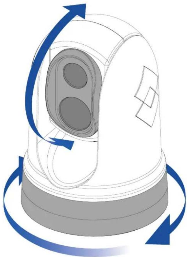
natural_image
Illustration of a warning light with blue circular arrows indicating clockwise rotation (no text or symbols)•Pancontinuouslythrough360°.
- Tiltto+110°/-90°relativetothecamerabase.
- Zoomthethermalcameraimage.
Y oucancontrolpan,tilt,andzoom,using:
• thecamera'swebbrowserinterface:seep.75—Webinterfaceoperation
•theJoystickonaJCUremotekeypad:seep.82—JCU-2controlsoverview
- thetouchscreenofacompatibleRaymarineMFD:seethe"Videoapp"sectioninthe documentationsuppliedwithyourMFD.
Homeposition
Thehomepositionisapresetpositionforthecamera.
Thehomepositionusuallydefinesausefulreferencepoint—forexample, straightahead and levelwiththehorizon.

•Thehomeiconisdisplayedmomentarilywhenyoucommandthe cameratomovetoitshomeposition.
- Thehomeiconflashes3timeswhenyousetthecamera'shome position.
Y oucansetthehomepositionasrequired, and return the camerato the home position, using:
- thecamera'swebbrowserinterface:seep.75—Webinterfaceoperation
•aJCUremotekeypad:seep.82—JCU-2controlsoverview - incompatibleRaymarineMFD:seethe"Videoapp"applicationsectioninthedocumentation suppliedwithyourMFD.
Surveillancemode
Insurveillancemodethecameracontinuouslypansleftandright,automaticallyscanning thescene.
Thecameracontinuesscanninguntilyou:
•disablesurveillancemode
•manuallypanortiltthecamera
•commandthecameratomovetoitshomeposition
Anyoftheseactionsstopssurveillancemode;surveillancemodedoesnotresumeuntilyoure-enableit.
Y oucancontrolsurveillancemode, includingthescanspeedandscanwidth, using:
- thecamera'swebbrowserinterface:seep.75—Webinterfaceoperation
• theuserprogrammablebuttonsonaJCUremotekeypad:see p.84—ConfiguringJCU-2user-programmablebuttons(UPBs) - incompatibleRaymarineMFD:seethe"Videoapp"sectioninthedocumentationsupplied withyourMFD.
Chapter6:Webinterfaceoperation
Chaptercontents
- 6.1Webbrowseruserinterfaceoverviewonpage76
- 6.2Settingupanetworkconnectiontothecameraonpage76
- 6.3 Logging into the Web browser user interface on page 77
•6.4Videofeedonpage78
•6.5 Camerasettingsmenusonpage79 - 6.6Systemsettingspage79
- 6.7T roubleshootonpage80
6.1Webbrowseruserinterfaceoverview
ThischapterdescribeshowtouseaWebbrowsertocommunicatewithandconfigure yourM300Seriescamera.
M300SeriescamerasarenetworkdevicesthatcommunicateoveranEthernetnetwork usingInternetProtocol(IP).UsingaWebbrowser,youcanviewvideo,controlthecamera, andchangecameraconfigurationsettings.
Note: Changesto configuration settings should only be made by some one who has expertise with M300 Series cameras and thorough understanding of how these settings affect the image. Haphazard changes can lead to image problems including a complete loss of video.
Y oucanusevarioustypesofIP-networkeddevicetointeractwiththecamera'sWebinterface (suchasalaptop,PC,tablet,orsmartphone). The device must be connected to the same networkasthecamera (or connected directly), and running as supported Web browser (Microsoft Internet Explorer version 9 or later, orthelatest version of the Google Chrome, Microsoft Edge, or Mozilla Firefox browsers).
Note:
- TocommunicatewithandconfigureyourM300SeriescamerausingaJCU-2control unit,refertop.81—JCU-2operation
- TocommunicatewithandconfigureyourM300camerausingaRaymarineLightHouse3 multifunctiondisplay(MFD),refertop.87—MFDoperation
6.2 Settingupanetworkconnectiontothecamera
Y ourcamerasupportsDHCPandUPnPtosimplifytheprocessoffindingthecameraona network, and connecting to it using a web browser.
Note: The web browser must be running on a device that is on the same network as the camera.
DHCP(Dynamikos control protocols) automatically assign to address and other important IP-network parameter stodevices on an network. The camera assetto use DHCP by default.
UPnUniversalPlugnPlayprotocolhatelptheameridentifysetother networkdevices.
Note: You should not attempt to set the camera's IP-network parameters manually unless you have previous experience with configuring IP networks.
T osetupanetworkconnectionbetweenyourIPdevice(suchasalaptoporPC),and thecamera:
1.
- If your system already includes an network switch (either a 3rd-partyswitch, or a Raymarine HS5 switch, forexample), connect both the camera and the IP device that will you web browser the switch (see. 52 Non-Ray Net system for example network connections). Then power-on the camera, network switch, and IP device.
- If you don't have any existing networking hardware (such as anetwork switch), connect theamer and device together directly (sep.52 Non-RayNet system for exemplenetwork connections). Then power-onthecamera, and IP device.
- MakesurethatyourIPdeviceis:
a. configuredtoobtainanIPaddressautomatically. For Windows7, 8, and 10:
GtControlPaneltheNetworkInSharingCenterChangedAdapter settings.
ii.Right-clickthenetworkconnectioncorrespondingtothewiredEthernetconnection onyourIPdevice(oftenlabelled"LocalAreaConnection")andselectProperties iii.SelecttheNetworkingtab.
iUndeThisconnectionseth following itemsselednterneProtocol Version4(TCP/IPv4).
v.SelectProperties.
vi.CheckthattheoptiontoObtainanIPaddressautomaticallyisselected.
b. configuredtodetectUPnPdevices. For Windows7, 8, and 10:
GtControlPanelNetworkSharingGenteAdvancedsharing settings
ii.CheckthattheoptiontoT urnonnetworkdiscoveryisselected.
- ThecameraisautomaticallyaddedtothelistofdeviceslocatedbyyourIPdevice, andisnamedaccordingtothecamerapartnumber,andserialnumber(forexample: E703531234).ForWindows7,8,and10,thecameraislistedinWindowsExplorer underNetwork.
Note: Depending your network configuration, it may take up to five minutes for the camerato appear in the list of devices. The camera is not listed after five minutes, double-check that your IP address is configured as described in step 2, then try renewing your IP device's IP address. For Windows 7, 8, and 10:
@StarRunthetypecmd(withouquotes)andlicDK.
b. In the Command Prompt window that opens, type "ipconfig/release" (without quotes), then press Enter.
c. Type "ipconfig/renew" (withoutquotes), thenpressEnter.
d.T ype"exit"(withoutquotes),thenpressEntertoclosethewindow.
UnderNetworkdouble-clickheamer@topetheamera'swebpage.show moreinformationaboutthecamera,includingitsIPaddress,right-clickthecamera itemandselectProperties.
6.3 Logging into the Web browser user interface
Y oucanlogintothecamera'sWebinterfaceusing:
-Username:
admin
•Passadbrdn
Thadmitoginaaccesthe
Maintenancenenandthethemenuaswells
createuseraccountsandchangeloginpasswords.
Y oushouldchangethedefaultloginpasswordstoppreventunauthorizedlogin.
Note:
Onlytwowebsessionscanbeactiveatonce.
T loign:
Gotothecamera'swebpageby:
enteringamera's address directly in the address bayouwebrowserOR
- double-clickingthecamerain"MyNetworkPlaces"(WindowsXP)or"Network"(later versionsofWindows).
(Seepp7.6 -76Setting up a Spatngork reconnection to the cabreactivation information.)
Theloginscreenisdisplayed:

Enter
admifdUseNamend
adminfoP:
Firsttimelogin
Aftersuccessfullyloggingintothewebinterfaceforthefirsttime,youwillbepromptedto enteranewsecurepasswordforfutureuse.
| NewPasswordmust: •Contain12characters •Containatleast1lower-casecharacter •Containatleast1upper-casecharacter | Change Password Password Confirm password Save |
6.4Videofeed
Afterlogginginyoucanviewtheliveimagefromthecamera'scurrentvideostream.
Settings
Fromthetoprightmenuyoucan:
- changebetweenthevisibleandthermalstreamsusingtheVandTicons.
- settheLiveVideoRefreshRate
- Changecameramovementcontrolsetting:
- Joystick—pressingandholdinganedgeofthevideostreamwillpan/tiltthecamerain thatdirectioncontinuouslyuntilreleased.
- Crosspressingnywheretheidestreamwipan/titheamerathlocation pressedbecomethenewcentreofthestream.
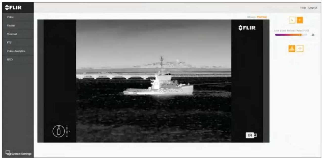
6.5 Camerasettingsmenus
Youcanaccessdifferentcamerasettingsmenusontheleftsideofthevideostream.The settingscontainedinthesemenupagescanbeusedtoconfigureyourcamera.
• Video—Editgeneralvideosettings.
•Visible—Editthevisiblecamerasettings.
• Thermal—Editthethermalcamerasettings.
- PTZ(PanTiltZoom)—EditthePanTiltandZoomsettingsandcontrolthecamera.
VideoAnalyticsEdMVAMarineVideoAnalyticsandobjectecdetectionsettings.
- OSD(OnScreenDisplay)—Edittheon-screenstatus symbols and icons displayed on the video feed.
6.6Systemsettings
You can access advanced cameras settings and diagnostic information by selecting Settings at the bottom of the screen.
•Network
- Date&Time
-Users
JCU
•T emperature
•Cyber
•ONVIF
- Firmware&info
System
6.7T roubleshoot
SettingastaticIPaddress
Insomecircumstances,youmayneedtosetastaticIPaddressforthecamera'sIP-network, ratherthanrelyingontheautomaticIPaddressesprovidedbytheDHCPservice(the camera'sdefaultsetting).
Note: Unless you are specifically instructed in FLIR documentation, or have previous experience of configuring IP networks, you should NOT attempt to set the camera's IP-network parameters manually. If you miss configure the IP-network parameters, your cameramay stop working correctly or become inaccessible on thenetwork.
Thisprocedureassumesthatyouhavealreadyestablishedanetworkconnection,andcan accessthecamera'sWebinterface(see).T oconfigurethecamera'sIPnetworkparameters manually:
- IntheInternetExplorerBrowser, typethecameralPaddressintotheaddressbar.
Thecamera'swebinterfaceisdisplayed
2th UseNameboxypéexpertithPasswordboxypéexpertthealick Login.
TheLiveVideopageisdisplayed.
3th top menulic Configuration the left-hand menulic Server LAN Settings.
Thecamera'snetworkoptionsaredisplayed.
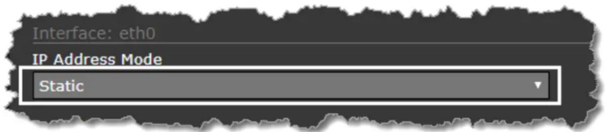
- MakeanyrequiredchangestothelP-networkparameters("LANSettings"). The following exampleshowshowtosetastaticIPaddress:
lthInterfacethSectionpageforthAddressModisselect Static.
Adjust the values of Address and Net mask required to the network your camera will be connected to. Theremaining parameters are not likely to require changes.
Note: Keep record address show with Address below the Address
Modelist.Youwillneedthisaddressstoaccessthecamera'sconfigurationwebinterface infuture.
5.AtthebottomoftheLANSettingspage,clickSave.
Aninformationdialogconfirmsthatsettingshavebeenchanged, and thatanetwork restart required.
©JicRestaNetwork.
Aninformationdialogconfirmsthatthenetworkhasrestarted, and that you may need to enter anew IP address store gain access to the camera's Web interface.
Chapter7: JCU-2 operation
Chaptercontents
- 7.1MainMenuonpage82
•7.2JCU-2controlsoverviewonpage82
7.1MainMenu
Y oucanaccessandcontrolthecamera's willbeoverlaidonthevideofeed.
MainMenuviaaconnectedJCU-2.Themenu
- Use the Menubutton on the JCU-2 to turn the OSD (onscreendisplay) Main Menu on or off.
•TheJoystickcanbeusedtonavigatethroughthemenus. - PresstherightJoystickbuttontoselecteachmenu.
- PresstheleftJoystickbuttontoexitthemenu.
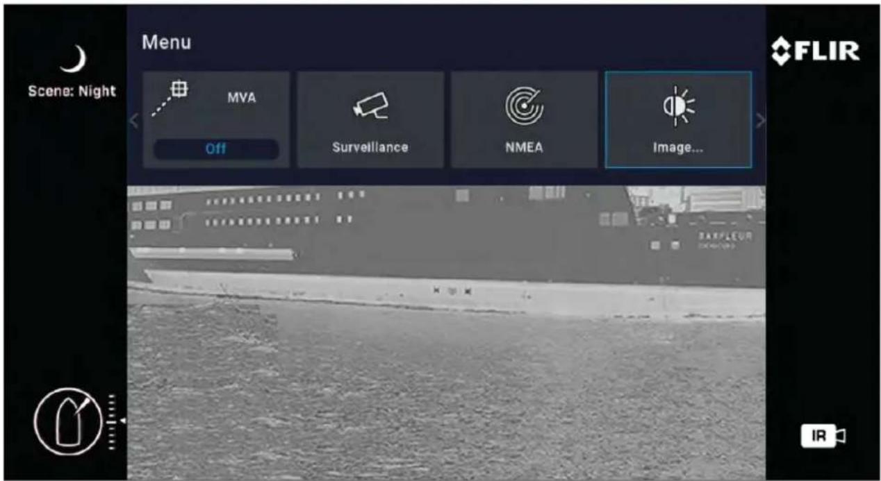
MainMenultems
- ParkCamera—thecamerawillpanandtilttoitspredefinedParkposition.Thepark positioncanbeeditedfromtheWebinterface,seep.75—Webinterfaceoperation
•MVA—accessMVA(MarineVideoAnalytics Cuba)settings.
Surveillancetheamera wientesurveillancenodepansontinuouslyandght untilitistakenoutofsurveillancemodeoruntiltheJCUmovesthecamera.
•NMEA—enableordisabletheprocessingofmessagesusingtheNMEAinterface.
- Image—accessadvancedimagesettings.
- Settings—accessadvancedcamerasettings.
•Help—opensthehelpmenu.
7.2JCU-2controlsoverview
ThecameracanbecontrolledwithaJCU-2.
Note:
•TheJCU-2joystickcontrolunitisavailableseparatelyasanoptionalaccessory.
• FormoreinformationonothercompatibleJCUunitsreferto p.23—Compatiblejoystickcontrollers(JCU)
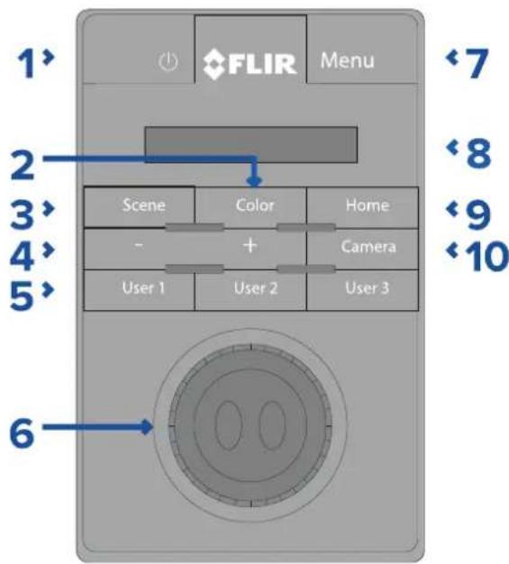
| 1 | POWER•PresscycleJCU-2displaybrightness Dim >Normal>Bright.•Pressandholdtowakecameraorenter powermenu. |
| 2 | COLOR•Presstochangepalette.•Pressandholdtochangepolarity. |
| 3 | SCENE•Presstochangescenesettings. |
| 4 | MANUALFOCUS•+—PresstoadjustthermaleZoom. |
| 5 | USER1,USER2,USER3•Userprogrammablebuttons(configuredviacamerawebpage:seep.84—ConfiguringJCU-2user-programmablebuttons(UPBs).Default actionis“toglerear-viewmirrormode”. |
| 6 | JOYSTICKT oManageCamera•T wisttozoomcamera.•Pushfore/afttotiltcamera.•Pushleftorrighttoroatecamera.T oNavigateOn-ScreenMenus•Pushleft/right/up/downtohighlth menuitem.•Pushrightjoystickbuttontoselectmenu item.•Pushleft/righttochangenumericvalue.•Pushrightjoystickbuttontotoggleswitch.•Pushleftjoystickbuttonontoexitcurrent menuitem.T oNavigateJCULCDMenu•Pushfore/afttoscrollup/down.•Pushleftjoystickbuttontoselectmenu item. |
| 7 | MENU•Presstoenableon-screenmenu.•Presstoexitmenu. |
| 8 | LCDDISPLAY•DisplaysJCUinformationandpowermenu options.•Usejoysticktointeract. |
| 9 | HOME•Presstoreturntohomeposition.•Pressandholduntilhomeiconflashes tostorenewhome. |
| 10 | CAMERA•Presstoselectactivecamera. |
ConfiguringJCU-2user-programmablebuttons(UPBs)
Note: The JCU-2 joystick control unit is available separately as an optional accessory.
The JCU-2 keypad's user-programmable buttons (UPBs) can be configured using the camera's Web interface. Form more information on accessing the Web interface, per to p.75—Web interface operation
Y oucanassignadifferentactiontoeachUPB(forexample,"Verticalstabilization",or "Surveillancemode")onaper-camerabasis.
Note: UPB mappings apply to individual cameras rather than specific JCU-2 key pads. This mean that, if you are using a single JCU-2 keypad to control two M300 Series cameras, UPB number 1 could be configured to initiate adifferent action one each camera.
T oconfigureJCU-2userprogrammablebuttons(UPBs)usingthecamera'sWebinterface:
Frontheamera'WebInterfaceselect
TheSettingsmenusaredisplayed.
2.Fromthemenusatthetopselect JCU.
The JCU setting page is displayed.

- From the UPBButtonlist, select the button you wish to configure.
- From the UPBActionlist, choosethecamera action you wish to associate with that UPB button.
5.Repeatsteps3and4foreachUPByouwishtoconfigure. - Select SavetosavetheUPBConfiguration.
Chapter8:MFDoperation
Chaptercontents
•8.1 Overviewpage88
•8.2ClearCruisethermalanalyticsonpage88
•8.3Auto-trackingonpage89
8.1 Overview
Y ourcameracanbecontrolledusingaRaymarine™Lighthouse3MultifunctionDisplay.
FormoreinformationrefertoyourMFDmanual, http://www.raymarine.co.uk/manuals-documents/
8.2 ClearCruisethermalanalytics
ClearCruise™intelligentthermalanalyticstechnologyprovidesaudibleandvisualalertswhen "non-water"objectsareidentifiedinthescene.
Boats, obstacles, and navigation markers can all be automatically identified in a sequence by ClearCruise ^TM .
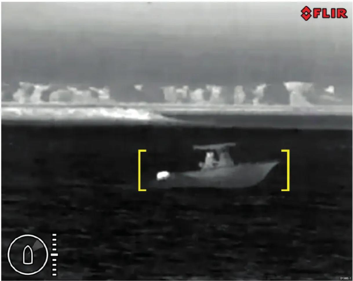
Y oucanactivateClearCruise™ and control "beepondetection", using incompatible Raymarine MFD: seethe "Camera" application section in the documentations supplied with your MFD.
Note: T ouseClearCruise™, yoursystemmustincludeacompatibleRaymarine®MFD runningLightHouse™3software.
Note: ClearCruise™ detection performance is dependent on conditions, and is not a replacement form maintaining a visual watch.
Important: ClearCruise™ ObjectDetectionisonlycompatiblewithcamerasthatare positionedupright.ClearCruise™ ObjectDetectionwillnotfunctionwithcamerasthatare upsidedownorhaveverticalflipenabled.
8.3 Auto-tracking
Y oucansetthecameratoautomaticallytrackthefollowingtargets:
•manoverboard
•dangerousAIStarget
•dangerousMARPAtarget
Y oucanactivateauto-tracking, and control which types of target are tracked, using a compatible Raymarine MFD: seethe "Videoapp" section in the documentations supplied with your MFD.
Note: T ouseauto-tracking, yoursystemmustincludeacompatibleRaymarineMFD.
Chapter9: Maintenance
Chaptercontents
•9.1 Service and maintenance on page 92
•9.2Cleaningthecameraonpage92
9.1 Service and maintenance
Thisproductcontainsnouserserviceablecomponents.Pleasereferallmaintenanceand repairtoauthorizedFLIRdealers.Unauthorizedrepairmayaffectyourwarranty.
9.2Cleaningthecamera
The camerahousingandlenswillrequireoccasionalcleaning.Y oushouldcleanthelenswhen imagequalitydegradationisnoticedorexcessivecontaminantbuildupisseen.Cleanthe interfacebetweentheyokeandbaseoftentopreventaccumulationofdebrisorsaltdeposits.
Whencleaningthisproduct:
- DoNOTwipethelenswindowwithadrycloth,orwithabrasivematerialssuchaspaper orscrubbrushes,asthiscouldscratchthecoating.
- DoNOTuseacidorammoniabasedproducts.
- DoNOTpressurewash.
Particularcareshouldbetakenwhencleaningthelenswindow, this has a protective anti-reflective coating which may be damaged by improper cleaning.
- Switchoffthepowertotheunit.
- Cleanthecamerabodywithaclean,softcottoncloth. You can moistenthecloth and use amilddetergentif required.
-
Cleanthecameralens.
-
Rinsethelenswithfreshwatertoremovealldirtparticlesandsaltdeposits,and allowtodrynaturally.
- Ifanyspotsorsmearsremain, verygentlywipethelenswindowwithacleanmicrofibre clothorsoftcottoncloth.
- If necessary, use isopropylalcohol (IPA) or amilddetergent to remove any remaining spots or marks.
Chapter10:Systemchecksandtroubleshooting
Chaptercontents
•10.1 Thermalcameratroubleshootingonpage94
•10.2FLIRMaritimeproductsupportandservicingonpage95
10.1 Thermal cameratroubleshooting
Problemswiththethermalcameraandtheirpossiblecausesandsolutionsaredescribedhere.
| ProblemPossiblecauses | Possiblesolutions | |
| Videonotdisplayed. | CameraisinStandby mode. | Thecamerawillnotdisplayvideoifitisin Standbymode.Usethecameracontrols (eitherethermalcameraapplicationor JCU)to“wake”thecamerafromstandby. |
| Problemwiththe thermalcameranetwork connections. | •Checkthermalcameranetworkcables (RayNetorEthernet)aresoundand properlyconnected. | |
| Problemwithpower supplytothecamera orJCU(ifusedasthe primarycontroller) | •Checkthepowerconnectionstothe cameraandJCU/PoEinjector(if used).•Ensurethatthepowerswitch/breaker ison.•Checkthefuse/breakerstate. | |
| Cannotcontrolthermal camerafronRaymarine displayorkeyboard. | Thermalcamera applicationisnot running. | Ensuretheremalmacereapplicationis runningonthemultifunctiondisplay(as opposedtothevideoapplicationwhich doesnothavecameracontrols). |
| Erraticorunresponsive controls. | Networkproblem. | Checkthatthecontrollerandthermal camerarecorrectlyconnectedthe network(Note This may direct connectionviaaRaymarinenetwork switch.) |
| CheckthatstatusfthRaymarine networkswitch. | ||
| CheckthatSeaT alk ^hs /RayNetcablesare frefordamage. | ||
| Controlconflicte.g. caused by multiple usersal different stations. | Ensurthatotherontrollerar in usatthesametime. | |
| Problemwith the controller. | Checkpowernetworkablingthe controllerandPoEinjector(PoEnly usedwithoptionalJoystickControlUnit). | |
| Checktherontrollersavailable.Ifothercontrollersareoperatingthis williminathpossibilitymore fundamentalcamerafault. | ||
| Imagetoodarkortoo light. | Displaybrightnesssis sebolow. | Usethebrightnesscontrolsatthedisplaytadjustaccordingly. |
| TheSceneModeis notappropriateforthe currentconditions. | Aparticularenvironmentmaybenefitfrom adifferentSceneModesettingfor example,everoldbackground(such asthesky)couldcausethecamera toseawidertemperaturerangthan appropriate. Usethe SCENEbutton. | |
| Imageisinverted (upsidedown). | Camera“Balldown” settingisincorrect. | EnsurethattheBalldownsettingisset correctly. |
10.2FLIRMaritimeproductsupportandservicing
FLIRprovidesacomprehensiveproductsupportservice,aswellaswarranty,service,and repairs.Y oucanaccesstheseservicesthroughtheFLIRwebsite,telephone,ande-mail.
Productinformation
If you need to request service or support, please have the following information to hand:
- Productname.
- Productidentity.
- Serialnumber.
- Softwareapplicationversion.
- Systemdiagrams.
Y oucanobtainthisproductinformationusingthemenuswithinyourproduct.
Servicingandwarranty
FLIRoffersdedicatedservicedepartmentsforwarranty,service,andrepairs.
Don't forgettovisittheFLIRwebsitetoregistryyourproductforextendedwarrantybenefits: http://customer.flir.com/Warranty/EndUserRegistration.
| Region | T elephone | |
| UnitedKingdom(UK), EMEA,andAsiaPacific | +44(0)1329246 932 | emea.service@flir.com |
| UnitedStates(US) | +1(603)324 7900 | rm-usrepair@flir.com |
Websupport
OntheFLIRwebsite,pleasevisitthe"Marine"portalsupportarea:http://www.flir.com/marine/support
T elephoneande-mailsupport
| Region | T elephone | |
| UnitedKingdom(UK), EMEA,andAsiaPacific | +44(0)1329 246777 | maritimecamerasupport@flir.com |
| UnitedStates(US) | +1(603)324 7900(T oll-free: +8005395539) | support@flir.com |
| AustraliaandNewZealand | +6128977 0300 | aus.support@flir.com (FLIRMaritimesubsidiary) |
| France | +33(0)14649 720 | support.fr@flir.com (FLIRMaritimesubsidiary) |
| Germany | +49(0)40237 808 | support.de@flir.com (FLIRMaritimesubsidiary) |
| Italy | +39029945 1001 | support.it@flir.com (FLIRMaritimesubsidiary) |
| Netherlands | +31(0)263614 905 | support.nl@flir.com (FLIRMaritimesubsidiary) |
| Sweden | +46(0)317633 670 | support.se@flir.com (FLIRMaritimesubsidiary) |
| Finland | +358(0)207 619937 | support.fi@flir.com (FLIRMaritimesubsidiary) |
| Norway | +4769264600 | support.no@flir.com (FLIRMaritimesubsidiary) |
| Denmark | +45437164 64 | support.dk@flir.com (FLIRMaritimesubsidiary) |
Chapter11:T echnicalspecification
Chaptercontents
•11.1M300Seriescamerasonpage98
•11.2JCU-2onpage99
11.1M300Seriescameras
T echnicalspecification
| Nominalsupplyvoltage12or24Vdc | |
| Operatingvoltagerange | -10%to+30%ofnominalsupplyrange |
| Current | Peak10.0A |
| Powerconsumption•41Wtypical | •56Wtypical(withheaterson)Note:FLIRrecommendsusinga75Wpower supply |
| Environmental | •Operatingtemperature:-25°Cto+55°C(-13°Fto131°F)•Storagetemperature:-30°Cto+70°C(-22°Fto158°F)•Relativehumidity:max95%•Wateringressprotection:IPx6•Wind:100mph(161kph)•Vibration:IEC60945;MIL-STD-810E•SaltMist:IEC60945 |
| Electromagneticcompliance | EMI:IEC60945 |
| Dimensions | Camera:•Basediameter:222.2mm(8.7in.)•Height:328.3mm(12.9in.)Cameraattachedtomountingriser:•Basediameter(withoutseal):252.3mm(9.9in.)•Basediameter(withseal):254.0mm(10.0in.)•Height:365.5mm(14.4in.) |
| Weight | 6.3kg(13.9lb)withoutmountingriser;6.75 kg(14.9lb)withmountingriser |
| Pan/tilt | •360°continuousspan•+110°/-90°tilt |
Videospecification
| Video•VideoResolution:1920x1080pixels | (progressivescan)IPdigitalvideoformat:H264-encodedIPvideostream,compatiblewithONVIFProfileSIPdigitalvideoformat:MPEG-encodedIPvideostream(accessibleviaWebinterface only)•HD-SDIdigitalvideoformat:SMPTE-292M |
| Visiblelightopticalsensor | •Sensorresolution:refertocomparison tablebelow•FieldofView:refertocomparisontablebelow•OpticalZoom:30x•DigitalZoom:12x |
| Thermalsensor | •Sensorresolution:refertocomparison tablebelow•FieldofView(FOV):refertocomparison tablebelow•DigitalZoom:4x |
| Model | Visiblelightsensor | Thermalsensor | ||
| Resolution | FOV | Resolution | FOV | |
| M332(9Hz)(E70528) - | - | 320x256pixels | 24°(H)x18°(V) | |
| M332(30Hz)(E70527) - | - | 320x256pixels | 24°(H)x18°(V) | |
| M364(9Hz)(E70526) - | - | 640x512pixels | 24°(H)x18°(V) | |
| M364(30Hz)(E70525) - | - | 640x512pixels | 24°(H)x18°(V) | |
| M300C(30Hz)(E70605) | 1920x1080 pixels | 64°(H)x60°(V) | - | |
| M364CLR(9Hz)(E70521) | 1920x1080 pixels | 64°(H)x60°(V) | 640x512pixels | 18°(H)x18°(V) |
| M364CLR(30Hz)(E70520) | 1920x1080 pixels | 64°(H)x60°(V) | 640x512pixels | 18°(H)x18°(V) |
| M364C(9Hz)(E70519) | 1920x1080 pixels | 64°(H)x60°(V) | 640x512pixels | 24°(H)x18°(V) |
| M364C(30Hz)(E70518) | 1920x1080 pixels | 64°(H)x60°(V) | 640x512pixels | 24°(H)x18°(V) |
11.2JCU-2
T echnicalspecification
Powerspecification
| PoEclass | Class1 |
| Nominalsupplyvoltage | •PoE:48Vdc•Alternatepower:12V/24Vdc |
| Operatingvoltagerange | •PoE:44Vto57Vdc•Alternatepower:9Vto32Vdc |
| Powerconcentrationfullkeypad | Illumination |
Environmentalspecification
| Operatingtemperature-25°Cto- | -55°C(-13°Fto131°F) |
| Storagetemperature-30°Cto+70°C(-22°Fto158°F) | |
| Relativehumidity | Maximum93% |
| Waterproofrating | IPx6&IPx7 |
Wiredconnections
| Network/PoE1xRJ45Ethernet10 | /100Mb/sconnector |
Chapter12:Sparesandaccessories
Chaptercontents
•12.1M300Seriescamerasparesandaccessoriesonpage102
•12.2FLIRnetworkingaccessoriesonpage103
•12.3RayNettoRJ45adaptercablesonpage104
•12.4RayNettoRayNetcablesandconnectorsonpage105
12.1M300Seriescamerasparesandaccessories
Accessories
| ItemPartnumber | |
| RayNet-to-RJ45adaptercable,120mm(4.7 in) | A80513 |
| RJ45Coupler(WaterproofEnclosure) | 4115028 |
| JCU-1remotecontrolunit | 500–0385–00 |
| JCU-2remotecontrolunit | 500–0398–10 |
| JCU-3remotecontrolunit(withportraitand landscapekeypadmats) | A80510 |
| PoweroverEthernet(PoE)5-portnetwork switch | 4141042 |
| 12VPoweroverEthernet(PoE)Injector | 4113746 |
12.2FLIRnetworkingaccessories
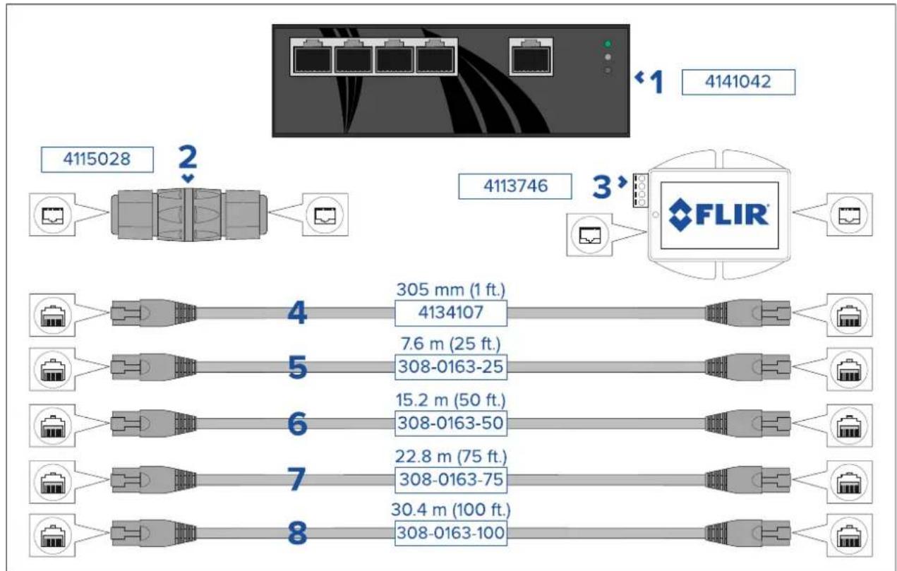
flowchart
graph TD
    A["4115028"] --> B["Port 2"]
    B --> C["Port 3"]
    C --> D["FLIR"]
    D --> E["Port 4"]
    E --> F["Port 5"]
    F --> G["Port 6"]
    G --> H["Port 7"]
    H --> I["Port 8"]
    style A fill:#f9f,stroke:#333
    style B fill:#ccf,stroke:#333
    style C fill:#cfc,stroke:#333
    style D fill:#fcc,stroke:#333
    style E fill:#cff,stroke:#333
    style F fill:#ffc,stroke:#333
    style G fill:#ffc,stroke:#333
    style H fill:#ffc,stroke:#333
    style I fill:#ffc,stroke:#333
| 1 | Power-over-Ethernet(PoE)networkswitch.4-portIEEE802.3at-compliantPoEfunction with30Wpoweroutputperport. |
| 2 | RJ45coupler,forjoining2separateRJ45networkcablestogethertoachievelonger cableruns. |
| 3 | Power-over-Ethernet(PoE)injector.Suppliespowertoanon-PoEneworkconnection.T ypicaluseisforpoweringaJCUcontrollerthatisconnectedtoanon-PoEnetwork switch. |
| 4 | 305mm(1ft.)RJ45-to-RJ45Ethernetcable,doubleshieldedwithLSZHlow interferencejacket. |
| 5 | 7.6m(25ft.)RJ45-to-RJ45Ethernetcable,doubleshieldedwithLSZHlow interferencejacket. |
| 6 | 15.2m(50ft.)RJ45-to-RJ45Ethernetcable,doubleshieldedwithLSZHlow interferencejacket. |
| 7 | 22.8m(75ft.)RJ45-to-RJ45Ethernetcable,doubleshieldedwithLSZHlow interferencejacket. |
| 8 | 30.4m(100ft.)RJ45-to-RJ45Ethernetcable,doubleshieldedwithLSZHlow interferencejacket. |
12.3RayNettoRJ45adaptercables
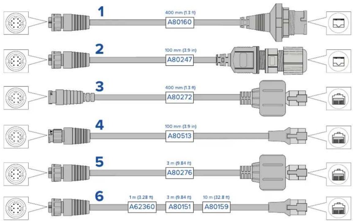
| Description | |
| 1 | AdaptercablewithaRayNet(female)socketononeend,andawaterproof(female)socketontheotherendacceptingthefollowingcableswithanRJ45SeaT alk hswaterprooflocking(male)plug:•A62245(1.5m).•A62246(15m). |
| 2 | AdaptercablewithaRayNet(female)socketononeend,andawaterproof(female)RJ45socketontheotherend,alongwithalockingglandforawatertightfit. |
| 3 | AdapterablewithRayNet(male)plugonend andRJ4SeaTalk hswaterproof(male)plugontheotherend. |
| 4 | AdapterablewithRayNet(male)plugonend andRJ4SeaTalk hs(male)plugontheotherend. |
| 5 | AdapterablewithRayNet(female)socketonend andRJ4SeaTalk hswaterproof(male)plugontheotherend. |
| 6 | AdapterablewithRayNet(female)socketonend andRJ4SeaTalk hs(male)socketontheotherend. |
12.4 RayNettoRayNetcablesandconnectors
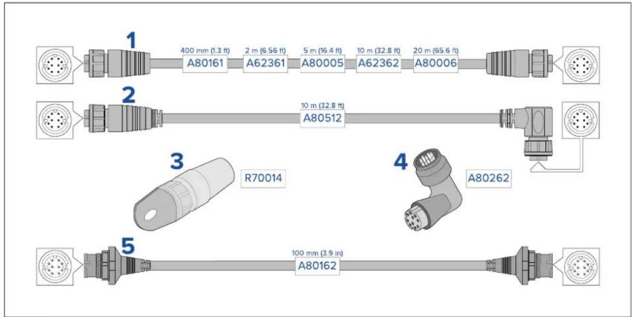
| Description | |
| 1 | StandardRayNetconnectioncablewithaRayNet(female)socketonbothends. |
| 2 | Right-angleRayNetconnectioncablewithastraightRayNet(female)socketon oneend, andaright-angleRayNet(female)socketontheotherend. Suitablefor connectingat90°(rightangle)toadevice, forinstallationswherespaceislimited. |
| 3 | RayNetcablepuller(5pack). |
| 4 | RayNettoRayNetright-anglecoupler/adapter. SuitableforconnectingRayNetcables at90°(rightangle)todevices, forinstallationswherespaceislimited. |
| 5 | AdaptercablewithaRayNet(male)plugonbothends. Suitableforjoining(female) RayNetcablestogetherforlongercableruns. |
Index
A
Accessories....102
Networkadaptercables....104
Networkcables....105
Networking....103
RayNetcables....105
Applicableproducts....16
B
Ball-downmode....72
Boxcontents, SeePartssupplied(JCU-2),
SeePartssupplied(M300)
C
Cable
Bendradius....44
Protection....44–45
Routing....44
Security....44
Strainrelief....44
Cameracontrooptions....66
Cameraimage....66
Cameraorientation....31
Ball-down....31
Ball-up....31
ClearCruise....19,21,88
Colormodes....71
Compasssafedistance....27
Compatiblehardware
JCU....23
MFD....23
Connectingcables....46
Connection
Power....59
Connections
Battery....61
Distributionpanel....60
Generalcablingguidance....44
NMEA0183....49
Contactdetails....95
D
DeclarationofConformity....12
E
ElectromagneticCompatibility....11
EMC, See Electromagnetic Compatibility
Environmentalspecification....100
F
Flushmounting....39
H
Homeposition....73
|
Installation
Bestpractice....63
Cameraorientation....31
Dimensions
JCU-2....30
M300....28-29
JCU-2....38
Locationrequirements....26,31
Mounting
JCU-2....39-40
M300....33,35
Mountingriser....29
Toolsrequired....27
Interference....27
SeealsoCompasssafedistance
IPaddress
static....80
J
JCU
JCU-1....23
JCU-2....23,30
JCU-3....23
Overview....82
JCU-2
Controls....83
UPBs....84
K
Keypadmatfitting....41
keypadmatremoval....38
L
Locationrequirements....31
M
Maintenance....10,92
MFD
Auto-tracking....89
ClearCruise....88
Overview....88
Mountingriser....35
N
Network
cables....103
PoE....103
switch....103
Networkconnections....17
T ypicalsystem....17
NMEA0183
Baudrate....49
NMEA0183connection....49
0
Operation
Ball-downmode....72
Cameracontroloptions....66
Cameracontrols
Homeposition....73
Pan,tilt,zoom....73
Surveillancemode....74
Cameraimage....66
Colormodes....71
JCU....82
MFD....88
Reversevideo....71
Scenepresets....71
Statusicons....67
Thermalcamera....67
Webbrowser....76
P
Pan,tilt,zoom....73
Partssupplied(JCU-2)....22
Partssupplied(M300)....21
PoEspecification....99
Power
Batteryconnection....61
Distribution....60
Distributionpanel....60
Fuseandbreakerratings....63
Grounding....63
Sharingabreaker....60
Powercableextension....62
Powerconnection....59
Powerconsumption....99
Powerspecification....99
Productoverview....19–20
Dualpayload....20
Singlepayload....19
Productrecycling(WEEE)....12
Productsupport....95
R
RayNet
cables....104–105
Reversevideo....71
S
Scenepresets....71
ServiceCenter....95
Servicing....10,92
Spares....102
Statusicons....67
Surfacemounting....40
Surveillancemode....74
Systemsettings....79
T
T echnicalspecification....98
T echnicalsupport....95
T emperaturerange....100
Thermalcamera....67
W
Warranty....95
Wateringress....100
Webbrowser
Login....77
networkconnectionsetup....76
Overview....76
Settings....79
WEEEDirective....12
FLIR Maritime US Inc.
9 Townsend West
Nashua, NH 03063
United States of America
Telephone: (+1) 603-324-7900
Raymarine UK Limited
Marine House
Cartwright Drive, Fareham, PO15 5RJ
United Kingdom
Telephone: (+44) (0)1329 246 700
CE

FLIR®
The World's Sixth Sense®