
UT211B - Multimeter Uni-T - Gratis brugsanvisning og manual
Find enhedens vejledning gratis UT211B Uni-T i PDF-format.

Brugerspørgsmål om UT211B Uni-T
0 spørgsmål om dette apparat. Besvar dem du kender, eller stil dit eget.
Stil et nyt spørgsmål om dette apparat
Download vejledningen til din Multimeter i PDF-format gratis! Find din vejledning UT211B - Uni-T og tag din elektroniske enhed tilbage i hånden. På denne side er alle dokumenter nødvendige for brugen af din enhed offentliggjort. UT211B af mærket Uni-T.
BRUGSANVISNING UT211B Uni-T
UT211A/B 60A Mini Clamp Meters Operation Manual
I. Overview
Ui211 mini digital clamp meter features high reliability and safety, automatic measurement and small size, and can exactly measure small signal current with a resolution up to 0.1 mA. The product chip is set with VFC start mode and will filter out high-frequency interfering signal by specific filter circuit so as to obtain accurate measurement. It can be applied in occasion with VFC conversion voltage or current and the combination of full-range overload protection function and particular appearance design has made it a new practical electrical measuring instrument with more remarkable performance.
II. Unpacking Inspection
Unpack the instrument and check it carefully for any absence or damage, if any, please contact with your supplier immediately.
Operation Manual 1
AAA Battery X1.5 V 2 Certificates of Quality
III. Safety Notice
The product design meets IEC/EN61010-1 and EN61010-2-033. Please read the operation manually before use and comply with all safety instructions.
-
Please use the clamp meter according to the operation manual, or else its safety function may not able to ensure your safety.
-
Please comply with national safety regulation to wear personal protective equipment to avoid damage caused by arc discharge in case the live conductor is exposed.
-
Please do not hold it by any part except for protection plate of current clamp.
-
Please check the current clamp meter, outer shell or insulation wire for any crack or damage before each use, and then check all parts for loose joint, especially for insulation part around the rim lock.
-
Please take off the clamp meter from all alive circuits and disconnect the leading wire before removing the battery cover.
-
Please do not use the clamp meter in the circuit with 600V or above voltage or 400Hz or above frequency
-
Over-voltage level: CATII 600V/CATIII300V, pollution class 2, category III device is used to protect distribution panel, feed line, shunted circuit and lighting protection facilities in large-scale building or other fixing equipment from damage caused by transient voltage. category II is for measurements performed on circuits directly connected to the low voltage installation. Examples are measurements on household appliances, portable tools and similar equipment.
-
Working at the exposed conductor must be done with extreme caution since it may lead to electric shock by contacting with the conductor.
-
Please pay special attention to 60V DC, 30V AC or 42V AC (peak value) or above voltage since they have risk of electric shock.
-
This product has a maximum measurement voltage of 600 V, and the safety standard complies with CE/ETL certification (EN61010-1, EN61010-2-033, and EN61010-2-032).
-
C This product has been tested to the requirements of CAN/CSA-C22.2 No. 61010-1, second edition, including Amendment 1, or a later version of the same standard incorporating the same level of testing requirements 'ETL'CONFORMS TO UL STD, 61010-1, IEC STD 61010-2-032, CERTIFIED TO CSA STD C22.2 No. 61010-1, 61010-2-032
IV. Electrical Symbols
| Low battery | Warming | ||
| AC (alternating current)/DC (direct current) | Double insulation |
| mA≡ | AC (alternating current)/DC (direct current) | Diode | |
| • 10) | Buzzer on/off | Earthing | |
| Danger-high voltage | |||
| CE | Conform to European Union directive | ||
V. Comprehensive Standards
-
protection will be impaired if used in a manner not specified by the manufacturer.
-
The protection voltage for maloperation between input terminal and ground is 600 V at most.
-
Maximum overload protection for current clamp terminal is 100A (CE).
- Maximum display: 6,000 Counts, 2\~3 updates every second. "OL" displays for over-range.
Full-scale value for capacity is 6200, and frequency is 9999. Diode: about 3.2 V.
Range: automatic
Polar: automatic
Working temperature: 0°C-40°C
Relative humidity: above ≤75% for 0°C \~30°C, ≤50% for 30°C \~40°C. Storage humidity: -10°C \~50°C
- Electromagnetic compatibility
Under 1V/m RF field: overall accuracy=specified accuracy+5% range. There is no specified indicator for 1V/m RF field.
-
Working altitude: 0\~2000m
-
Built-in battery: AAA 1.5V×2
-
Low battery: "☐" symbol displays on LCD
-
Overall dimension: about (175×60×33.5) mm, maximum opening for clamp is 17mm.
-
Weight: about 170g (including batteries)
-
Safety standard: IEC/EN 61010-1, EN61010-2-033; EN61010-2-032; CAT III 300V/CAT II 600V; pollution class 2
-
Use a test probe CAT II 600V, CAT III 300V or better which meet the requirements of IEC 61010-031
VI. Product Panel Graphics(Figure 1)
1. Clamp head
-
Clamp trigger (press the trigger to open the clamp).
-
NCV indicator (it will send alarming sound and flashing light when the inductive AC filed >100V).
-
Function select button (to shift ACV/DCV/Hz, resistance Ω/diode/capacity, current ACA/DCA, NCV, OFF).
-
HOLD/2 Backlight key (to measure read lock/long press it for 2 seconds to start backlight).
-
ZERO key ( to return DCA to zero, measure the relative value of capacity/voltage).
-
SELECT key (function select mode, such as ACV/DCV/Hz, resistance /diode/capacity, ACA/DCA)
-
LCD display (measuring fund
-
LDB display (including nanoscale symbol, value and other display interface).
-
Positive input jack (insert the red probe in the jack when testing voltage/frequency and resistance/capacity/diode).
-
COM input jack (insert the black probe in the jack when testing voltage/frequency and resistance/capacity/diode).

VII. Panorama View of LCD(Figure 2)
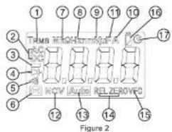
| NO | Symbol | Description |
| 1 | TRMS | Prompt for true RMS measurement |
| 2 | AC/DC | Prompt for AC/DC voltage measurement |
| 3 | — | Negative reading |
| 4 | ▶ | Diode measurement prompt |
| 5 | •) | Circuit on/off detection prompt |
| 6 | H | Data hold prompt |
| 7 | Ω kΩ MΩ | Unit of resistance: ohm, kill-ohm, megaohm |
| 8 | Hz kHz MHz | Unit of frequency: Hz, kHz, MHz |
| 9 | mV. V | Unit of voltage: millivolt, volt |
| 10 | mA. A | Unit of current: microampere, milliampere, ampere |
| 11 | nF μF mF | Unit of capacity: nanofarad, microfarad, millfarad |
| 12 | (EF)NCV | Sensor prompt for non-contact AC voltage |
| 13 | Auto | Prompt for auto range |
| 14 | ZERO/REL | Base number zero/relative measurement prompt |
| 15 | VFC | Conversion voltage/current measurement prompt |
| 16 | ∠ | Built-in battery under-voltage prompt |
| 17 | ○ | Auto-off prompt |
VIII. Operation Instructions
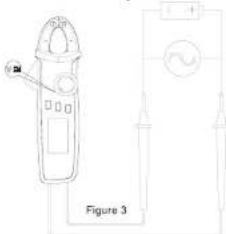
- AC/DC voltage/HZ measurement
- Select AC voltage and Hz or DC voltage.
- Insert the red probe in the red jack (positive terminal) and black probe in the black jack (COM terminal).
● Touch the tested component, such as power socket, with red and black probe (Figure 3).
● ead the measured value on LCD.
When measuring the voltage, the maximum input voltage allows a maximum of 600V (AC/DC). If the limit value is exceeded, there will be risk of electric shock, or damage to the instrument.
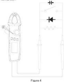
- Resistance/diode/circuit on/off/capacity measurement
● Insert the red probe in the red jack (positive terminal) and black probe in the black jack (COM terminal).
- Connect the probe in parallel with the tested component to measure.
● Read the measured value on LCD
When measuring the voltage/capacity/diode range, voltage input above DC 60 V or AC 30V is not allowed to avoid personal injury.
Product before use, please measure known AC voltage. (such as electric socket), confirm the readings about 220V, can be normal use!
- AC/DC current measurement (Figure5, Figure6)
1) AC current
- Select range for AC current (600mA \~ 6,000mA \~ 60A \~).
- Open the clamp head and attach the wire on the hook (single wire). Ensure that the hooks are totally closed and no gap existing between them.
● Read the measured value on LCD.
2) DC current
- Press SELECT key to enter in the DC current range (6,000mA, 60A)
- Press ZERO key to return the reading to zero. Press several times to zero it if one press fails to achieve it. Note: In consideration of the product's high sensitivity, the clamp hook should be in the same direction of the measured object in process of zeroing so as to obtain accurate reading.
- Open the clamp head and attach the wire on the hook (single wire). Ensure that the hooks are totally closed and no gap existing between them.
● Read the measured value on LCD.
When measuring the current, please pull out the testing probe to avoid electric shock.
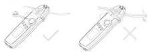
Figure 5
UNI-T

Figure 6
- NCV non-contact field measurement (Figure 7)
In order to detect AC voltage or magnetic field in some space, close the clamp head to the tested object by the front end to detect the motion. The analog quantity is about: "EF" when it < critical voltage; display as "-" when it > critical voltage V1. Section voltage is set as "-" and different motivating buzzing is associated to distinguish the intensity of detected field.
When it is shifted to NCV measurement, please pull out the testing probe to avoid electric shock.

Figure 7
- Other functions
● Long press HOLD key for about 2 seconds to start LCD backlight function
● Auto off: if the knob button gets no move for about 15 minutes in process of measurement, the instrument will enter in "AUTO OFF" mode to save power. Press any key under auto off mode to make the instrument "auto up", or shift the knob button to OFF to restart the instrument. - Press SELECT key in shutdown mode to power it on again, the buzzer will make 5 sounds to prompt the cancellation of auto off function. Turn it off and then restart, the auto off function will be recovered.
● The buzzer will send 5 continuous alarming sounds, and then 1 long alarming sound before the product automatically shut down. When the auto off function is canceled, it will send 5 alarming sounds every 15 minutes.
- Buzzer: When pressing any function key or turning any function switch that is workable, the buzzer will send a "Beep" sound (lasts for about 0.25 second). When measuring the voltage or current, the buzzer will also send a continuous "beep" intermittent sound to warm the outrange. The functions are as follows:
a) AC/DC voltage > about 600V
b) mAAC/DC current >620mA(or 6200mA)
c) AAC/DC large current
- Low voltage test: Test the internal VDD in process of power supply, when the voltage is lower than 2.5 V, it will display a low voltage symbol “Q” and display normally; When it is lower than 2.2V, it will display low voltage symbol only after startup, and unable to work normally.
- When the power voltage for the battery is lowered to be 2.6V, LCD backlight will be weak or not workable while the measuring function works normally.
IX. Technical Index
Accuracy: ± (a% reading +b digit), guarantee period in 1 year. Environmental temperature: 23°C ±5°C (73.4°F ±9°F) relative temperature: 75%
1.DC Voltage Measurement
| Range | Resolution | Accuracy | |
| UT211A | UT211B | ||
| 600.0mV | 600.0mV | 10μV | ± (0.7% + 5) |
| 6.000V | 6.000V | 1mV | ± (0.7% + 3) |
| 60.00V | 60.00V | 10mV | |
| 600.0V | 600.0V | 0.1V | |
| 600V | 600V | 1V | |
⚠️ Input impedance
600mV range >1GΩ; for other ranges, the average of input impedance is 10MΩ. (600mV range open circuit may have instable digital display, and get to stable value < ±1 after being loaded.)
Maximum input voltage: ±600V
2.AC Voltage Measurement
| Range | Resolution | Accuracy | |
| UT211A | UT211B | ||
| 6.000V | 6.000V | 1mV | ± (0.8% + 3) |
| 60.00V | 60.00V | 10mV | |
| 600.0V | 600.0V | 0.1V | |
| 600V | 600V | 1V | ± (1.0% + 3) |
| V.F.C 200V~600V | 0.1V | ± (4.0% + 3) | |

Input impedance: input impedance is about 10 MΩ.
Maximum input voltage: 600Vrms
● Display True RMS. Frequency response: 45\~400Hz
● Accuracy guarantee scale: 5–100% of measuring range, <20 digit residual reading is allowed for short circuit.
- AC crest factor may reach 3.0 at 4,000 counts; for non-sinusoidal waveform, the error of crest factor increases with the following formula a). Add 3% when the crest factor is 1-2
b). Add 5% when the crest factor is 2-2.5
c). Add 7% when the crest factor is 2\~2.5
- Impedance Measurement
| Range | Resolution | Accuracy | |
| UT211A | UT211B | ||
| 600.0Ω* | 600.0Ω* | 0.1Ω | ± (1.0% + 2) |
| 6.000kΩ | 6.000kΩ | 1Ω | ± (0.8% + 2) |
| 60.00kΩ | 60.00kΩ | 10Ω | |
| 600.0kΩ | 600.0kΩ | 100Ω | |
| 6.000MΩ | 6.000MΩ | 1kΩ | ± (1.2% + 3) |
| 60.00MΩ | 60.00MΩ | 10kΩ | ± (1.5% + 5) |

7.10 Flange: Measured Value - Display Measurement Value - Proboshard-circuit value
Open circuit voltage is about 1 V
Open circuit voltage is usual. Overload protection: 600V-RTC
- Circuit on/off, diode measurement
| Range | Resolution | Remarks |
| · | 0.1Ω | Circuit off impedance value is set >150Ω, the beeper keeps silent.Circuit on impedance value is set ≤slant 10Ω, the beeper beeps continuously. |
| 1mV | Open circuit voltage is about 3.2 V; the normal voltage value is between 0.5~0.8V. |

2. 2018年第一季度报告
- Capacity Measurement
| Range | Resolution | Accuracy |
| 6.200nF | 1pF | In REL mode: ±(4%+10) |
| 62.00nF~620.0μF | 10pF~0.1μF | ±(4%+5) |
| 6.200nF~62.00nF | 1μF~10μF | ±10% |

BEI (UT3114) and ZERO (UT3115)
REL(OT21TA) and ZERO (OT21TB) measurement mode is suggested to ensure the accuracy when the tested capacity is ≤1μF.
6. ACV Frequency Measurement (Suitable for the industrial
frequency
| Range | Resolution | Accuracy |
| 10Hz~80KHz | 0.001Hz~0.01kHz | ± (0.1% +4) |

Input amplitude: ≥10V (DC level is
input equation = 10.7 (2.2 level is 6) when a frequency of 0.5 and are for reference only
. DC Current Measurement (UT211B only)
| Range | Resolution | Accuracy |
| 6000mA | 1mA | ±(2.0%+5) |
| 60.00A | 0.01A | ±(2.0%+3) |

2. Overseas protection: 100%
- AC Current Measurement
| Range | Resolution | Accuracy | ||
| UT211A | UT211B | 50Hz/60Hz | ≥100HZ | |
| 600.0mA | 600.0mA | 0.1mA | ±(1.5%+10) | ±(2.0%+10) |
| 6000mA | 6000mA | 1mA | ±(2.5%+5) | ±(3.0%+5) |
| 60.00A | 60.00A | 0.01A | ±(2.0%+5) | ±(2.5%+5) |
| V.F.C600.0mA~60A | 0.1mA/0.01A | ±(4.0%+10) | ||
Overload protection 109A
- Accuracy guaranteed scale: 5\~100% of measuring range, <20 digit residual reading is allowed for 600mA open circuit.
- AC crest factor may reach 3.0 at 4,000 counts; for non-sinusoidal waveform, the error of crest factor increases with the following formula.
a) Add 3% when the crest factor is 1\~2
b) Add 5% when the crest factor is 2\~2.5
c) Add 7% when the crest factor is 2.5-3
Overload protection: 600V-PTC
X. Maintenance and Repair
Warning: Ensure that the power is off and the probe is got off the terminal and tested circuit before opening the back cover of the instrument.
- Regular maintenance and repair
- Please clean the outer shell of instrument with wet cloth and
- mild detergent without abrasive compound or solvent content. - In case of any abnormality, the instrument must be stopped and sent for repair.
- If the instrument needs any verification or repair, it must be conducted by competent professional personnel or designated maintenance department.
- Replace the battery (See Figure 8)
When the LCD gives low battery prompt "Q", it indicates the built-in battery must be replaced immediately, or else the measuring accuracy cannot be guaranteed.
Battery specification: AAA 1.5 V x 2

Figure 8
- Operation Steps:
- Shift the power switch to "OFF" and pull the probe out of input
jack - Twist off the fixing screw on the battery cover with a screw driver
and remove the cover to take off the old battery as shown. - Install two new batteries (AAA 1.5V).
The specification is subject to change without prior notice.
Manufacturer:
Uni-Trend Technology (China) Limited
No 6. Gong Ye Bei 1st Road
Songshan Lake National High-Tech Industrial
Development Zone, Dongguan City
Guangdong Province
China
Postal Code:523 808
Headquarters
Uni-Trend Group Limited
Rm901, 9/F, Nanyang Plaza
57 Hung To Road
Kwun Tong
Kowloon, Hong Kong
Tel: (852) 2950 9168
Fax: (852) 2950 9303
Email: info@uni-trend.com
http://www.uni-trend.com

Mærke : Uni-T
Model : UT211B
Kategori : Multimeter