
85346126 - Bevægelsesdetektor HAGER - Gratis brugsanvisning og manual
Find enhedens vejledning gratis 85346126 HAGER i PDF-format.


Brugerspørgsmål om 85346126 HAGER
0 spørgsmål om dette apparat. Besvar dem du kender, eller stil dit eget.
Stil et nyt spørgsmål om dette apparat
Download vejledningen til din Bevægelsesdetektor i PDF-format gratis! Find din vejledning 85346126 - HAGER og tag din elektroniske enhed tilbage i hånden. På denne side er alle dokumenter nødvendige for brugen af din enhed offentliggjort. 85346126 af mærket HAGER.
BRUGSANVISNING 85346126 HAGER
KNX radio motion detector comfort 1.1 m quicklink
KNX radio motion detector comfort 2.2 m quicklink
Safety instructions
Electrical equipment must only be installed
and assembled by a qualified electrician in accordance with the relevant installation stand-
ards, regulations, directives and safety and accident prevention directives of the country.
Failure to comply with these instructions may
result in damage to the device, fire or other hazards.
The radio transmission is not suitable for safe-
Due to its detection behaviour the device is not
suitable for use in burglary detection or alarm systems.
These instructions are an integral component
of the product and must be retained by the end user.
Design and layout of the device
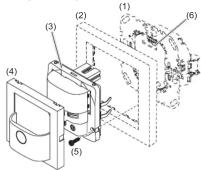
Fig. 1: Design and layout of the device
(1) Insert
(see "Accessories", not in scope of delivery)
(2) Frame (not included)
(3) Application module
(4) Motion detector design cover
(5) Module retaining screw (not for Berker R 1/R 3
(6) Interface between insert/application module
Function
System information
This device is a product of the quicklink system, in which installation devices communicate via radio signals.
quicklink stands for a configuration mode, in which the function related connection between trans
the function-related connection between transmitters and receivers is set on the device through
buttons and displays without further tools.
All devices configurable by quicklink can be operated together in one system.
▶ See configuration instructions
This device complies with EU Directive 2014/53/EU. The declaration of conformity and further system
The declaration of conformity and further system information can be accessed at hager.com.
The device may be operated in all EU and EFTA
states (exclu
Correct use
- Automatic switching of lighting depending on host motion and ambient brightness.
heat motion and ambient brightness Application module for switch insert
- Application module for switch insert, dimmer insert or power supply for KNX radio applica-
tion module
- The device has been designed for smaller ap
plications, in which a maximum of 20 devices are allocated
- Only suitable for use in indoor areas with no
drip and no spray of water
Product characteristics
- quicklink functions to extend the detection ar-
ea, scenes, control circuits ▶ See configuration instructions
- Remote control via quicklink tran
- Remote control via quicklink transmitter Integrated button for selecting operating
- Integrated button for selecting operating modes and special functions
- Lockable integrated button
- The operating modes Automatic, Permanent
ON, Permanent OFF can be selected
- Display operating mode via LED
- Potentiometer for setting the response bright-
ness and detection sensitivity
- Adjustable detection angle for adapting the detection prop
- Additional adjustment of the response bright-
Additional adjustment of the ness via Teach-In function
- Party function
- Presence simulation
- Optional extension unit operation via installa-
tion button
Automatic mode
The motion detector detects heat motion caused by people, animals, or objects.
by people, animals, or objects. On switch insert and dimmer insert with factory
setting:
- The light will be switched on for a fixed delay
time of 3 minutes if movements are detected in the detection area and the set brightness
threshold is undershot. Each additional move-
ment in the detection area restarts the delay
time.
- The light will be switched off after 3 minutes if no additional movements are detected.
On dimmer insert configured with time function (see configuration instructions):
- The light will be switched on for the delay time, if movements are detected in the detection area and the set brightness threshold is undershot. Each additional movement in the detection area restarts the delay time.
- After the delay time elapses, the lighting will be dimmed to 50% of the switch-on brightness level and will remain at this brightness level for 30 s (switch-off pre-warning). Any motion detected during the switch-off pre-warning restarts the delay time and restores the switch-on brightness level.
- The light will be switched off if no motion is detected any longer in the detection area and the set delay time and the switch-off pre-warning have elapsed.
Performance after mains breakdown/return of mains supply
- Mains breakdown shorter than 0.2 s:
The function is not impaired.
- Mains breakdown longer than 0.2 s;
There is no function during the mains break-down. The current configuration is saved in
down. The current to non-volatile memory.
- Return of mains supply:
The application module executes an initialisation for approx. 5 s, during which the lighting will be switched on. Motion detection starts thereafter. If no motion is detected during the first 5 s, the lighting is switched off. The saved configuration is loaded from memory. During this period, local operation via the button or extension unit can be used.
Operation
Operating concept

Fig. 2: Display and operating elements
(7) Button
(8) Status LED
Operation is executed by pushing the button (7) on the motion detector:
- A short press of the button switches the operating modes. The operating mode is displayed via the status LED behind the optics cover of the motion detector.
- Keeping the button pressed activates special functions. Selection of the special functions is supported by the LED display (Fig. 3).
Selecting the operating mode
■ Briefly press the button repeatedly until the
desired operating mode is selected.
The status LED indicate ing mode (see Table 1)
Switching the operating mode finishes the party function or presence simulation, if these functions were previously active.
Disabling/enabling operating mode selection via button
- Keep the button pressed for more than 15
seconds, until the status LED is flashing green (Fig. 3)
Selection of the operating mode via the button
is disabled.
■ Keep the button pressed for more than 15 seconds, until the status LED is flashing green (Fig. 3).
The operating mode can be selected via the
button again.
Switching on the lighting via push-button extension unit or changing the switch-on brightness level
Optionally, the lighting can be switched on via a mechanical push-button extension unit (Table 2).
For extension unit operation, the lighting is switched on independently of the set brightness threshold.
When using the dimmer inserts, the last set brightness level will be saved as the switch-on brightness level.
Activating/interrupting party function
The party function switches the lighting on for 2 hours. During this time, no extension unit or radio commands are executed.
- Keep the button pressed for more than 5 seconds, until the status LED flashes red (Fig. 3). The lighting is switched on for 2 hours. During this time the status LED is flashing red. When the 2 hours have elapsed, the motion detector switches to the Auto operating mode.
■ Briefly press the button.
The party function is interrupted and the motion
detector reverts to the Auto operating mode.
Activating/deactivating the presence simulation
During operation, the motion detector counts the motion detections in one full hour and saves the result. With active presence simulation at the beginning of the hour with the most detections saved, the light will be switched on for the duration of the delay time, even no motion is detected.
During the presence simulation, presence detection, extension unit and radio commands will continue to be executed normally.
■ Keep the button pressed for more than 20 seconds, until the status LED slowly flashes red (Figure 3).
The presence simulation is active. During this time the status LED lights orange. The motion detector switches the lighting on at the saved time.
■ Briefly press the button.
The presence simulation will be deactivated, the motion detector reverts to the Auto operating mode.

^1) Only on universal switch insert and universal dimmer insert
Fig. 3: Selection of special functions and LED display
| LED display | Operating mode | Description |
| -- | Auto | Motion and brightness-dependent switching on/switching off of the load |
| Green | Permanent ON | Load is permanently switched-on/switched-off. |
| Red | Permanent OFF | Extension unit signals, as well as radio signals, will not be evaluated |
Table 1: Display of operating modes
| Dimming status | Operation button | Performance of the insert |
| Motion detector applied on switch insert | ||
| OFF | Short press | Load is switched on for the set delay time |
| ON | Short press | Extension of switch-on time by the set delay time |
| Motion detector applied on push-button | dimmer comfort 1gang | |
| OFF | Short press | Load is switched on to the switch-on brightness level for the set delay time |
| ON | Short press | Extension of switch-on time by the set delay time at the same brightness |
| OFF | Long press | Load is switched on to switch-on brightness-level, subsequent dimming in the opposite direction of the last dimming process. Thereafter the load remains switched on for the delay time |
| ON | Long press | Changes the current brightness. Dimming takes place in the opposite direction of the last dimming operation until maximum or minimum brightness. Subsequently the load remains switched on at the set brightness for the set delay time |
Table 2: Operation via push-button extension unit
Settings
Setting response brightness via Teach-In
function
The response brightness is the brightness value saved in the motion detector: when this value
is undershot the motion detector switches the
connected load if movements are detected. Via Teach-In function the current ambient bright-
Reason in function the current ambient brightness is saved as the response brightness.
The load is switched off.
- Keep the button pressed for more than 10
seconds, until the status LED flashes orange (Fig. 3).
The motion detector detects the current
ambient brightness and saves it as response brightness
brightness
i Setting of the response brightness via Touch In function and via the brightness
Teach-In function and via the brightness potentiometer has the same priority. Teach-In
overwrites the response brightness set on the brightness potentiometer. If the setting is
the brightness potentiometer. If the setting is made again via the potentiometer, the
Teach-In figure will be overwritten.
Setting the load
If the switching performance is not satisfactory
after commissioning when using the motion detector on universal switch inserts and universal
toster on an inverse switch inserts and an inverse touch dimmers, a load setting must be carried out.
A load setting is required each time the load is changed.
is changed:
■ Switch oil load.
- Keep the button pressed for more than 25 seconds, until the status LED is slowly
25 seconds, until the status LED is slowly flashing orange.
■ Release push-button.
The connected load flashes once. The
device is in selection mode
If no further actions are performed within the
next 10 seconds, the dimmer switches to normal operation.
normal operation.
■ Briefly press the bottom button repeatedly to activate the desired setting mode.
▶ See Table 3a / 3b
Information for elects
Information for electricians: For the version labelling of the flush-m
ed insert, see packaging label or sticker on
the back of the housing.
Operating and assembly
instructions
D
B
D.
Berker
KNX radio motion detector comfort
1.1 m quicklink
Order no. 8534 51
KNX radio motion detector comfort
2.2 m quicklink
Order no. 8534 61 ..
EN
Berker GmbH & Co. KG
Zum Gunterstal
66440 Blieskastel, Germany Tel: +49 6842 945.0
Fax: +49 6842 945 4625
e-mail: info@berker.de
www.berker.com

Berker
04/2022
6LE005217D
[Non-Text]
[Non-Text]
[Non-Text]
[Non-Text]
[Non-Text]
[Non-Text]
[Non-Text]
[Non-Text]
[Non-Text]
[Non-Text]
Setting the load on a universal switch or dimmer insert from Version R1.2
| Briefly press the button | Setting mode | Duration and confirmation of the load setting¶ The light to confirm the load flashes at 50% brightness. | Information for use |
| 1 x Load | factory setting | Settings duration: approx. 30 sec.¶ Load switching/dimming phases may occur during the automatic settings process.The load flashes one last time as a confirmation and then goes out. The device returns to normal operation. | Factory setting with automatic load recognition.If the switching behaviour is unsatisfactory after that, restart selection mode and select the best option. |
| 2 x | LED mode 1 (phase cut-on) | After approx. 5 sec., the load flashes twice as a confirmation and then goes out. The device returns to normal operation. | Recommended for lower 230 V LED loads up to max. 60 W if the switching/dimming behaviour is unsatisfactory after automatic load setting. |
| 3 x | LED mode 2 (phase cut-on) | Settings duration: ≤ 50 sec.¶ Load switching/dimming phases may occur during the automatic settings process.Finally, the load flashes three times as a confirmation and then goes out. The device returns to normal operation. | Recommended for higher 230 V LED loads from 50 W, which can be operated in the phase cut-on. Observe manufacturer's data! |
| 4 x | Fine setting of minimum brightness | 5 predefined minimum brightness levels for 2.5 sec. each, run through repeatedly (3 runs).■ As soon as the connected load shows a satisfactory minimum brightness, confirm by quickly pressing the bottom button.After approx. 5 sec., the load flashes four times as a confirmation and remains switched on (50% brightness). The device returns to normal operation. | To optimise the switch-on behaviour, or if the load flickers in the lower dimming range, the minimum brightness setting can be manually adjusted here. |
Table 3a
Setting the load on a universal switch or dimmer insert up to Version R1.1
| Briefly press the button | Setting mode | Confirmation of the load setting | Information for use |
| 1 x Load | fine-setting | Load flashes 1 x after approx. 30 s and changes to normal operation. | Not suitable for ohmic loads (e.g. incandescent, HV halogen lamps); use factory load setting.If the load fine-setting does not bring any improvement for energy-saving lamps or 230 V LED lamps, select the energy-saving lamp fine-setting or 230 V LED lamp universal setting. |
| 2 x | Load factory setting | Load flashes 2 x after approx. 6 s and changes to normal operation. | |
| 3 x | Energy-saving lamp fine-setting in phase cut-on | Load flashes 3 x after approx. 30 s and changes to normal operation | Energy-saving lamps are switched on at a brightness level of at least 50% in order to ensure an ignition process. |
| 4 x | 230 V LED lamps Universal setting in phase cut-on or phase cut-off | Load flashes 4 x after approx. 5 s and changes to normal operation | For connected dimmable 230 V LED lamps the dimming principle and the optimal switch-on brightness level is set automatically. |
| For all settling modes | Load flashes 5 x | The selected setting mode is not supported by the insert. |
Table 3b
Information for electricians
Installation and electrical connection
Selecting installation location
A minimum distance between the transmitter and corresponding receiver of about 1 m must be maintained.
A minimum distance to electronic devices which emit high frequency signals such as computers, electronic transformers or microwave devices of approx. 0.5 m must be maintained.
| Material | Degree of material penetration |
| Wood, plaster, plaster-board, uncoated glass | approx. 90 % |
| Brick, press boards | approx. 70 % |
| Reinforced concrete, underfloor heating | approx. 30 % |
| Metal, metal grids, aluminium laminates, coated glass | approx. 10 % |
| Rain, snow | approx. 1 ... 40 % |
Table 4: Material penetration
Mounting on or close to metal surfaces may cause impairment of the radio transmission. Take material penetration into account. The range of the system can be optimised by selecting the best possible mounting location:
i Observe the motion orientation: A distinction is made between "direct approach" and "transverse motion". Motions transverse to the motion detector can be detected better than motions toward the motion detector (Figure 4).
■ Select an installation location that is free of vibration. Vibrations can cause undesired switching.
■ Avoid sources of interference in the detection area (Fig. 6 and 7). Sources of interference, e.g. heating elements, ventilation systems, air conditioners and lamps that are cooling down can cause undesired switching (Fig. 4).
To avoid disturbing influences, the detection angle can be restricted (see Restriction of the detection area).
Assembly of the device (Figure 1)
Information on electrical connection are to be taken from the operating instructions of the insert.
■ Attach the application module (3) together with frame (2) to a suitable insert (1) and establish a connection between insert and the application module via the plug-in interface (6).
As soon as voltage is supplied to the application module, the status LED indicates the compatibility with the insert used.
| Status LED display | Meaning |
| LED flashes green (approx. 5 s until motion detection is active) | Compatible |
| LED flashes red for 5 s | Not compatible. |
| LED flashes orange for 5 s | Compatible, but not configured to each other. For a new configuration, the application module must be reset to the factory setting. |
■ If available, fix dismantling protection
screw (5)
■ After radio configuration (see configuration instructions) and commissioning, snap the design cover (4) onto the application module (3).
Commissioning
Overview of operation and adjustment elements

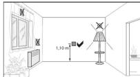
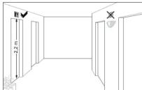
Fig. 4: Installation location of the motion detectors

Fig. 5: Operating and adjustment elements of the bottom part of the application module
(9) Potentiometer for sensitivity
(10) fct button
(11) Detection angle adjuster
(12) Status/fct LED
(13) cfg button/LED
(14) Potentiometer for response brightness

Fig. 6: Detection area of the motion detector for installation height 1.1 m
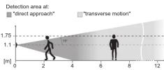


Fig. 8: Setting the detection angle
Setting the detection area
The detection angle can be restricted for the right side and for the left side via each adjuster (Fig. 5, 10) between 45^ and 90^ for each adjuster. This can be carried out on the device. The detection angle can therefore be between 90^ and 180^ (Fig. 8).
■ Use the adjusters to set the detection angle for each side.
Setting the detection performance
Test mode must be used to test the detection performance. In test mode, the motion detector works independent of brightness. Each detection switches the lighting and the status LED on for 3 seconds. The motion detection will then be deactivated for 2 seconds.
The motion detector is connected and ready for operation.
- Setting the test mode. To do this, set the response brightness potentiometer (Fig. 5, 13 to the T position. - Leave the detection area and observe the switching behaviour.
If the motion detector switches on without motion in the detection field, then sources of interference (see Mounting location) are present or the sensitivity is not too high.
■ Reduce the sensitivity if necessary and blank out sources of interference by adjusting the detection angle or removing them.
■ Check the detection area using a detection test and adjust if necessary.
If the detection area is too small, it can be extended via motion detector extension units or per radio via a master-slave configuration. See configuration instructions
Setting the response brightness
The response brightness is the brightness value saved in the motion detector; when this value is undershot the motion detector switches the connected load if movements are detected. The response brightness can be set between approx. 5 (€) through 150 Lux (factory setting) to daytime operation (○). The ○ symbol stands for independent of brightness switching. The response brightness can be variably adjusted in the intermediate areas.
In order to control the lighting in stairwells in accordance with DIN EN 12464-1, 2003-3, select the 150 Lux potentiometer setting.
■ Turn the response brightness potentiometer (Fig. 5, 14) to the desired position.
To save the current ambient brightness as response brightness, use the Teach-In function (see Setting the response brightness via Teach-In function).
Setting the sensitivity
Detection is factory-set to maximum sensitivity. If there are frequent incorrect detections, the sensitivity can be reduced. ■ Turn the sensitivity potentiometer (Fig. 5, 9) to the desired position.
Technical data
Connection Attachment to suitable insert
(see Accessories)
Power supply via insert Despersion brightness temp. F 4000 L/W (m)
Sensitivity approx. 10 ... 100 %
Detection angle approx. 90 ... 180°
Detection area (1.1 m) approx. 12 x 16 m
Detection area (2.2 m) approx. 8 x 12 m
Transmission frequency 868-870 MHz
Transmission power 25 mW Radio protocol KNX Radio PE1 M
quicklink logic functions max. 20 transmitters/
receivers
Receiver category 2 Transmittee duly Eagle ≤0.1%
Transmitter duty cycle 10.1% Degree of protection IP 20
Relative humidity 0 ... 65 % (no condensation)
Ambient temperature -5 ... +45 °C
Storage/transport temperature -20 ... +60 °C
Mounting orientation Interface between application and power module at top
Accessories
Relay insert 8512 12 xx
Universal switch insert 1gang 8512 11 xx
Push-button dimmer 1gang 8542 11 xx
Push-button dimmer comfort tgang 6542 12 xx Power supply for KNY radio
application module 8502 01 xx
Warranty
We reserve the right to realise technical and
formal changes to the product in the interest of technical progress.
Our products are under guarantee within the
scope of the statutory provisions.
If you have a warranty claim, please contact the point of only.


- KNX radio motion detector comfort 1.1 m quicklink
- Safety instructions
- Function
- System information
- states (exclu
- Correct use
- Product characteristics
- Automatic mode
- Performance after mains breakdown/return of mains supply
- Operation
- Selecting the operating mode
- Activating/interrupting party function
- Settings
- Setting the load
- KNX radio motion detector comfort
- Information for electricians
- Installation and electrical connection
- Assembly of the device (Figure 1)
- Commissioning
- Setting the detection area
- Setting the detection performance
- Setting the response brightness
- Setting the sensitivity
- Technical data
- Accessories
- Warranty
Mærke : HAGER
Model : 85346126
Kategori : Bevægelsesdetektor