
787-712 - Computeradapter Wago - Gratis brugsanvisning og manual
Find enhedens vejledning gratis 787-712 Wago i PDF-format.


Brugerspørgsmål om 787-712 Wago
0 spørgsmål om dette apparat. Besvar dem du kender, eller stil dit eget.
Stil et nyt spørgsmål om dette apparat
Download vejledningen til din Computeradapter i PDF-format gratis! Find din vejledning 787-712 - Wago og tag din elektroniske enhed tilbage i hånden. På denne side er alle dokumenter nødvendige for brugen af din enhed offentliggjort. 787-712 af mærket Wago.
BRUGSANVISNING 787-712 Wago
Gebrauchs- und Montageanleitung Bitte aufbewahren!

WAGO Kontakttechnik GmbH & Co. KG Hansastr. 27 D-32423 Minden www.wago.com

WAGO - Stromversorgungen Serie 787 Primär getaktete Gleichstromversorgung 787-712


Abb. 1: Primär getaktete Gleichstromversorgung 787-712
- Sicherheits- und Anwendungshinweise
Wir beglückwünschen Sie zum Erwerb dieses hochwertigen Produktes. In dem beschriebenen Anwendungsbereich wird es im bestimmungsgemäßen Betrieb lange seine Funktion erfüllen. Wie bei jedem technischen Produkt kann jedoch die Gefahr von schweren Personen- oder Sachschäden bei unsachgemäßem Einsatz, unzulässigem Entfernen von erforderlichen Abdeckungen, bei falscher Installation oder Bedienung bestehen. Folgen Sie dieser Gebrauchsanleitung, und verfahren Sie nach den anerkannten Regeln der Technik. Alle Arbeiten zur Installation, Inbetriebnahme und zum Betriebs sowie zur Instandhaltung sind von qualifiziertem Fachpersonal auszuführen (IEC 60364, VDE0105).
1.1 Verpackung
Bitte untersuchen Sie das Betriebsmittel sofort auf Transportschäden, wie Deformation und lose Teile. Beschädigungen bitte unverzüglich beim Transportunternehmen reklamieren; auch wenn die Verpackung äußerlich nicht beschädigt ist.
1.2 Lagerung
Zulässige Lagerungstemperatur: -25°C ... +85°C
Zulössige Luftfeuchtigkeit: 10 % 95 % relative Feuchte keine Betagung zulässig
Bei Langzeitlagerung: Betriebsmittel mit eingebauten Kondensatoren sind mindestens alle
2 Jahre für 5 Minuten an Netzspannung anzulegen.
1.3 Installation und Inbetriebnahme
Schützen Sie das Betriebsmittel vor unzulässiger Beanspruchung. Insbesondere beim Transport und bei der Handhablag dürfen keine Baulemente verbogen und/oder Isolationsabstände verderrt werden. Vermeiden Sie eine Berührung der elektrischen Baulemente und Kontakte. Hatten Sie den gefahrenen Minderstabstand zu beschätzten Teilten beinbrengt an, um die Kühlung nicht zu behindem (1996/95/05) und (2007/95/05) nach dem Betriebsmittel aus dem Betriebsmittel als 30 Jahre bis 18 Jahre bis 19 Jahre bis 19 Jahre bis 19 Jahre bis 19 Jahre bis 19 Jahre bis 19 Jahre bis 19 Jahre bis 19 Jahre bis 19 Jahre bis 19 Jahre bis 19 Jahre bis 19 Jahre bis 19 Jahre bis 19 Jahre bis 19 Jahre bis 19 Jahre bis 19 Jahre bis 19 Jahre bis 19 Jahre bis 19 Jahre bis 14 Jahre bis 14 Jahre bis 14 Jahre bis 14 Jahre bis 14 Jahre bis 14 Jahre bis 14 Jahre bis 14 Jahre bis 14 Jahre bis 14 Jahre bis 14 Jahre bis 14 Jahre bis 14 Jahre bis 14 Jahre bis 14 Jahre bis 14 Jahre bis 14 Jahre bis 14 Jahre bis 14 Jahre bis 14 Jahre bis 10 Jahre bis 10 Jahre bis 10 Jahre bis 10 Jahre bis 10 Jahre bis 10 Jahre bis 10 Jahre bis 10 Jahre bis 10 Jahre bis 10 Jahre bis 10 Jahre bis 10 Jahre bis 10 Jahre bis 10 Jahre bis 10 Jahre bis 10 Jahre bis 10 Jahre bis 10 Jahre bis 10 Jahre bis 10 Jahre bis 14 Jahre bis 14 Jahre bis 14 Jahre bis 14 Jahre bis 14 Jahre bis 14 Jahre bis 14 Jahre bis 14 Jahre bis 14 Jahre bis 14 Jahre bis 14 Jahre bis 14 Jahre bis 14 Jahre bis 14 Jahre bis 14 Jahre bis 14 Jahre bis 14 Jahre bis 14 Jahre bis 14 Jahre bis 12 Jahre bis 12 Jahre bis 12 Jahre bis 12 Jahre bis 12 Jahre bis 12 Jahre bis 12 Jahre bis 12 Jahre bis 12 Jahre bis 12 Jahre bis 12 Jahre bis 12 Jahre bis 12 Jahre bis 12 Jahre bis 12 Jahre bis 12 Jahre bis 12 Jahre bis 12 Jahre bis 12 Jahre bis 12 Jahre bis 10 Jahre bis 10 Jahre bis 10 Jahre bis 10 Jahre bis 10 Jahre bis 10 Jahre bis 10 Jahre bis 10 Jahre bis 10 Jahre bis 10 Jahre bis 10 Jahre bis 10 Jahre bis 10 Jahre bis 10 Jahre bis 10 Jahre bis 10 Jahre bis 10 Jahre bis 10 Jahre bis 10 Jahre bis 8 Jahre bis 8 Jahre bis 8 Jahre bis 8 Jahre bis 8 Jahre bis 8 Jahre bis 8 Jahre bis 8 Jahre bis 8 Jahre bis 8 Jahre bis 8 Jahre bis 8 Jahre bis
1.4 Wartung und Montage
Elektrische Betriebsmittel bedürfen in der Regel keiner besonderen Wartung, sind jedoch (entsprechend der Schutzart) vor Staubablagierung, Feuchte, Strahlung und aggressiven Chemikalien zu schützen. Die Instandsetzung ist nur im Rahmen der in dieser Gebrauchsanleitung aufgeführten Maßnahmen staathaft. Sollte es trotzdem einen Ausfall geben, schicken Sie bitte das Betriebsmittel zur Reparatur an uns ein. Geben Sie bitte Folgendes an: Art des Fehlers, Begleitumstände (Einsatzbedingungen, Beschaltung), eigene Vermutungen über die Fehlerursache, vorausgegangene ungewöhnliche Vorkommisse usw.
1.5 Entsergung
Bitte beachten Sie die aktuellen Bestimmungen, und entsorgen Sie je nach Beschaffenheit, z.B. Elektronikschrott (Leiterplatten), Kunststoff, Blech, Kupfer usw.
1.6 Änderungen
Unser Haus hat die Produktdokumentation mit großer Sorgfalt erstellt und geprüft. Es kann jedoch keine Gewährleistung bezüglich der Fehlerfreiheit und Vollständigkeit übernommen werden. Eine Übertragbarkeit der Angaben auf die jeweilige Anwendung ist zu prüfen. Die technischen Daten beschreiben die Eigenschaften des Produktes, ohne diese zuzusichern. Änderungen, die dem technischen Fortschritt dienen, sind vorbehalten.
2. Einsatzgebiet
Diese primär getaktete Gleichstromversorgung ist eine Einbaukomponente zur Energieversorgung von industriellen elektrischen und elektronischen Verbrauchern der Informationstechnik (IT), der Automatisierungstechnik, des Anlagenbaus, der Verfahrenstechnik, der Steuerungstechnik und der Gebäudeautomation. Ohne Zusatzmaßnahmen darf die Serie 787 nicht eingesetzt werden:
- an Orten mit hohem Anteil ionisierender Strahlung
erschwerten Betriebsbedingungen, z. B. durch
• Staubentwicklung
•ätzende Dämpfe oder Gase
• starke elektrische oder magnetische Felder
die einer besonderen Überwachung bedürfen, wie z. B.
Aufzugsanlagen
• elektrische Anlagen in besonders gefährleten Räumen
Eine Zusatzmaßnahme kann z. B. der Einbau der Serie 787 in einen Schrank oder in ein Gehäuse sein.
3. Normen
Die elektrische Sicherheit und EMV (Elektromagnetische Verträglichkeit) ist durch den Geräteaufbau entsprechend den angeführten Normen gegeben. Das Betriebsmittel entspricht den gesetzlichen Anforderungen und Normen zur C€-Konformität und trägt das C€-Zeichen.
4. Betriebshinweise
Die Kühlung des Betriebsmittels darf nicht beeinträchtigt werden. Stellen Sie eine ungehinderte Luftzufuhr und einen Mindestabstand von 15 mm zu benachbarten Teilen sicher. Die Verdrahtung der Anschlussklemmen darf nur im spannungsfreien Zustand erfolgen. Aufgrund der Schutzart IP20 ist der Betrieb des Betriebsmittels nur in trockenen Räumen zulässig. Eine Geräuschentwicklung im noch hörbaren Bereich ist abhängig vom Betriebszustand möglich.
5. Montagebinweise
Das Betriebsmittel ist auf TS35 (TS = Tragschiene) nach EN 60715 aufrastbar. Montieren Sie es zwecks ordnungsgemäßer Entwärmung horizontal (Luftein- bzw. -auslässe oben und unten). Abweichende Einbaulagen erfolgen auf eigene Gefahr. Wir empfehlen hierbei eine Ausgangsleistung von 50 % und eine Umgebungstemperatur von 45°C nicht zu überschreiten. Die Mindestabstände sind einzuhalten.
Montage
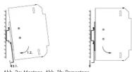
Die Stromversorgung wird mit dem an der Rückseite angebrachten Haken auf dem oberen Schenkel der TS35 eingehängt (vgl. Abb. 2a) und dann durch Drücken der Stromversorgung in Richtung Tragschiene und gleichzeitigen Zug auf der angrachten Lasche aufgerastet. Dementrass
Durch Ziehen an der unten angebrachten Lasche wird die Entriegelung der Tragschienenhalterung betätigt. Durch Kippen der Stromversorgung nach vorne kann diese dann aus der Tragschiene ausgehängt werden (vgl. Abb. 2b).
5.1 Anschlüsse
Überprüfen Sie vor Anschluss des Betriebsmittels die zugehörige Betriebsspannung (siehe Typenschild).
5.2 Anschlussklemmen
Der Anschluss der Versorgungsleitungen erfolgt auf der Primär- u. Sekundärseite über fest eingelötete WAGO-Klemmleisten Serie 745 mit CAGE CLAMP®-Anschlusstechnik. Primärseitig sind die schwarzen Klemmstellen für die Anschlüsse L N u. PF vorgesehen. Sekundärseitig sind je zwei blaue Klemmstellen für + und - vorhanden (val. Abb. 1).
4.10.2.2.3.
5.3 Verbindungsleitungen Die WAGO-Klemmleisten Serie 745 mit CAGE CLAMP®-Anschlusstechnik sind für Einzeladem bis zu 4 mm² (ein- oder feindräftig) geeignet. Beachten Sie bei der Dimensionierung der Leiterquerschnitte den möglichen Ausgangsstrom mit ca. 1,5 x 1 Bemessung.
6. LED
Eine grüne LED dient als Ausgangsspannungsindikator [DC OK]
eine rote LED signalisiert eine Überlast / Kurzschluss am Ausgang [Overload] (vgl. Abb.1).
- Einstellen der Ausgangsspannung
Mit dem frontseitigen Trimmpotentiometer [Adjust] kann von außen die Ausgangsspannung von
DC 22 V ... 28 V eingestellt werden (vgl. Abb.1).
8. Parallelschaltbarkeit (ausgangasseitig)
Stellen Sie beim Parallelbetrieb die Ausgangsspannung der parallel zu schaltenden Geräte möglichst exakt auf den gleichen Wert ein. Ferner müssen die Leitungswiderstände von den Netzteilen zur Last nahezu gleich sein. Zum Parallelschalten dürfen nur Geräte gleichen Typs verwendet werden.
Hinweise:
Bitte verwenden Sie zur Parallelschaltung externe Reihenklemmen. Eine Parallelschaltung direkt auf den sekundärseitigen Anschlussklemmen des Gerätes ist nicht zulässig. Zur Entkopplung der Ausgänge im Parallelbetrieb wird empfohlen, Dioden in den Pluspfad einzusetzen. Diese Dioden müssen für den max. Ausgangsstrom des Gerätes ausgelegt sein.
9. Einschaltstrom
Werden mehrere Geräte parallel geschaltet und eingangseitig über den gleichen Stromkreis versorgt, kann es zu hohen Einschaltströmen kommen. In diesem Fall empfiehlt sich die Verwendung von Hilfsrelais, die eine zeitliche Verzögerung des Einschaltens bewirken (vgl. Abb. 3).

Abb. 3: Paralleischaltung von Netzgeräten
Zur Reduzierung des Einschatstromimpulses enthält das Gerät einen NTC-Widerstand. Dieser ist auch temperaturabhängig. Bei sehr niedrigen Betriebstemperatures (z.B.- 10 °C) hat der NTC einen hohen Widerstand, was eventuell des Einschalten des Gerätes bei hoher Last verhindert. Schalten Sie das Gerät in diesem Fall im Stand-by-Betrieb mehrfach ein- und aus, verringem Sie die Last oder betreiben Sie das Gerät bei höherer Umgebungstemperatur. Die Anzahl der parallel an einem Stromkreis betriebenen Geräte ergibt sich aus der Summe der Ableitsströme der Filterkondensatoren. Dieser soll max. 3,5 mA gem. EN 60950 nicht überschreiten.
10. Kurzschluss- und Überlastverhalten
Der Ausgang des Betriebsmittels ist elektronisch vor Überlast und Kurzschluss geschützt.
Die Ausgangsspannung wird ab einem Ausgangsstrom von etwa 1,15 x l Bemessung reduziert (val. Abb. 4).
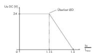
Abb. 4: Ausgangskennlinie
In diesem Fall leuchtet die rote LED [Overload]. Nach Entfernen der Überlast bzw. des Kurzschlusses liefert das Netzgerät automatisch wieder die eingestellte Ausgangsspannung.
11. Derating-Kurven
Die maximale Last ist abhängig von der Umgebungstemperatur
Über 50°C ist ein Derating von 3,3 %/K zu berücksichtigen (vol. Abb. 5)
Die maximale Last ist ebenfalls abhängig von der Eingangsspannung.
Bei Eingangsspannungen von kleiner AC 90 V ist ein Derating zu berücksichtigen (vgl. Abb. 6).

Abb. 5: Derating-Kurve
Abb. 6: Derating-Kurve
12. Technische Daten
Fingang (AC IN)
Eingangpanpuno
Eingangspansfeng
Lingangsspunhong
5
Frequenz:
Frequenzbereich
Eingangssstrom:
Spitzeneinschaftstrom:
Ableitstrom:
Leistungsfaktor:
Netzausfallüberbrückung:
Ausgang (DC OUT)
Ausgangsspannung:
Ausgangspannungsbereich
Ausgangspämm Regelgegeninkai
kegelgenlösigen
Kesrweiligkeir:
Ausgangsstrom
Wirkungsgrad/Verlustleistungen
Wirkungssarad
Absicherung
Interne Absicherung:
Empfohlene Vorsicherung:
Transientenüberspannungsschutz:
Anschluss
Anschlusstechnik:
Leiterart:
Oversch
Querschüme.
Abisolierlangen:
Eingangsseifig:
Ausgangsseitig
Abmessungen und Gewicht
Abmessungen (
Gewicht:

AC 100 V 240 V
AC 85V - 264V*
AC 05 V ... 204 V (* vzl Abb. 6)
( vgi. ABB. 6)
50 Hz ... 80 Hz 47 Hz ... 63 Hz
47 112 ... 03 112 0.7 A | i AG 820 X 1.0 A | i AG 115 Y
0,7 A Bel AC 230 V; 1,2 A Bel AC 115 V
< 30 A bel AC 230
< | mA
0,5
20 ms (bei AC 230 V)
[Non-Text]
DC 24 V [Voreinstellung]
DC 22 V ... 28 V einstellbo
1%
≤ 100 mVpp
2.5 A (val Abb 4)
1,5 A (vtg. Abb. 4)
typ 82%
F3 15 A / 250 V
Leitungsschutzscholter C10 bzw. B16
NITC
[Non-Text]
CAGE CLAMP® (WAGO-Serie 745)
Voll- oder Litzendraht
0.08 mm² 4 mm² / AWG 28-12
8.9 mm / 0.33 in
3 pole, schwartz für | N und PE
Spollg, Schwarz, for L,N and T
4-polig, bidu, fur 2x + und 2x -
50×92×136
(Höhe, eh Obergraste Tonnachtions)
(Holle du Oberkäufe hugschüttel) 470 -
470g
05.10 - 05.10
-25℃...+85℃
-10°C
95%
-3,3%
2 (nach EN 50178)
+/- 0,03 %/K für 0 °C < T < 55 °C
, , , ,
[Non-Text]
+100 °C heiß werden
oden
den und horizontaler Einbaulage
tion und honzommater Einbahnlage
15 mm
70 mm
[Non-Text]
vorbereitet für Schutzklasse I
IP20 nach EN 60529
Reduzierung der Ausgangsspannung (val. Abb.3)
im Bereich 1.15. 1.4 x | Bemessung
in
ja
μ
2 g gem. 60088-2-8
15 g gem. 60068:2:27
1,5 kV zw. Eingangsseite und PE
3,0 kV zw. Eingangs- und Ausgangsseite
0,5 kV zw. Ausgangsseite und PE
EN 60950
[Non-Text]
[Non-Text]
[Non-Text]
0109
gem. EN 01000-03
gem. E
[Non-Text]
9970-0966/0787-0712.17.04.2009
Technische Änderungen vorbehalten
![Wago 787-712 - [Non-Text] - 1](/content/2026/05/1010166/images/38b7a480311123da7529ba8121364afc0bbe11d9fc09be4b243fd369aed8a0b3.jpg)
Operating and Assembly Instructions Please retain!
![Wago 787-712 - [Non-Text] - 2](/content/2026/05/1010166/images/576ad5fbc8eb3b061d002f3408b9bb386de3ef1b4da22ec11c8b6e4a2681ab85.jpg)
WAGO Kontakttechnik GmbH & Co. KG Hansstr. 27 D-32423 Minden www.wago.com
![Wago 787-712 - [Non-Text] - 3](/content/2026/05/1010166/images/8ee15081d1c2590699dc984b84f12c3bf8cede729a32b2fcc435e0007202d00b.jpg)
WAGO 787 Series Power Supply Units 787-712 Primary Switch DC Power Supply Unit


Fig. 1: 787-712 Primary Switch DC Power Supply Unit
- Safety Information and Application Notes
Congratulations on your purchase of this high-quality product. When used as intended in the described scope of application, it will provide years of reliable service. As with every technical product, however, risk of personal injury or material damage can arise with improper use, inappropriate removal of necessary covers or incorrect installation or operation. Follow these operating instructions and proceed according to the accepted technology standards. All work relating to installation, startup and operation, as well as maintenance, must be performed by qualified specialists [IEC 60364, VDE 0105].
1.1 Packaging
Please inspect the equipment promptly for transport damages such as deformation and loose parts. Please report damages to the transport company immediately, even if the outer packaging is undamaged.
1.2 Storage
Admissible storage temperature: -25 °C to +85 °C
Admissible air humidity: 10% to 95% relative air humidity; no condensation
For long-term storage. Equipment with baller condensers must be attached to the
system voltage for at least 5 minutes every 2 years.
1.3 Installation and Startup
Protect equipment from inappropriate stress. Particularly during transport and handling, ensure that no parts are bent and that electrical spacing remains constant. Avoid touching the electrical components and contacts. Keep sufficient distance from adjacent parts as to the power of the circuit. The equipment is designed for a 200V DC/DC system with the power of the circuit assembly and wire the equipment when the power is disconnected. Observe the product description and the technical information in our main catalog, as well as the labels on the equipment and on the type plate. Use the following according to the local conditions: applicable regulations (e.g., VDE 0100), national accident prevention specifications (e.g., UVB/VB64 or BOV A2) and accepted requirements (e.g., VDB 0103). Use the equipment to ensure compliance with the low voltage directive (2006/95/EG). When installing in machines, normal operation must not commence until it is determined the machine complies with the requirements of the machinery directive (2006/42/EG); EN 60204 shall be observed. Commencement of the equipment is required to ensure compliance with the power of the equipment. The manufacturer of the system or machine is responsible to ensure compliance with the limit values required by EMC legislation.
1.4 Maintenance and Assembly
Electrical equipment does not typically require special maintenance; however, depending on the degree of protection, it must be protected from dust accumulation, moisture, radiation and aggressive chemicals. Repairs shall only be undertaken within the scope of the measures outlined in these operating instructions. If an equipment failure does occur, please send the equipment to us to be repaired. Please provide the following information: type of failure, attendant circumstances (operating conditions, wiring), assumptions about the cause of failure, previous uncommon occurrences, etc.
1.5 Disposal
Please observe current regulations and dispose of equipment according to material composition; e.g., electronic scrap (circuit boards), plastic, sheet metal, copper, etc.
1.6 Modifications
The product documentation has been prepared and checked with great care. However, no guarantee can be made regarding completeness and absence of failure. Any transfer of specifications to the respective application should be checked. The technical data describes the product characteristics but does not guarantee them. We reserve the right to make changes that further the technical progress.
2. Application Area
This primary switch DC power supply unit is a mounting component used to supply energy to industrial electric and electronic users of information technology (IT), automation, plant construction, process engineering, control engineering and building automation. Without additional measures, the 787 Series shall not be used:
- in places with a high concentration of ionizing radiation
- in places with difficult operating conditions; e.g.
• dust formation
*caustic vapors or gases
• Strong electric or magnetic fields
- In facilities which require special monitoring, e.g.,
• 1.1
An "additional measure" can be installing the 787 Series in a cabinet or a box.
3. Standards
Electrical safety and EMC (electromagnetic compatibility) is provided through the equipment configuration in accordance with the cited standards. The equipment conforms to the legal stipulations and standards for CE conformity and bears the CE sign.
4. Notes on Operation
The cooling of the equipment shall not be impaired. Ensure that the air supply is unobstructed and that a minimum distance of 1.5 mm is present between adjacent parts. The terminal strips shall only be wired when the power supply is disconnected.
Due to the IP20 degree of protection, the equipment shall only be operated in dry conditions.
"Depending on the operating mode, audible noise may develop."
5. Installation Instructions
The equipment can be mounted on DIN 35 rail in accordance with EN 60715. For consistent heat dissipation, mount horizontally (air inlet and outlet above and below). Other mounting positions should only be used at one's own risk. We recommend in that case not exceeding a power output of 50% and an ambient operating temperature of 45°C. The minimum distance requirements shall be met.
Assembly
The hook on the reverse side connects the power supply unit to the upper-shank of the DIN 35 rail (see Fig. 2a). The power supply unit then snaps in place by pressing it down in the direction of the rail and by simultaneously pulling the latch on the underside.
Disassembly By pulling the latch on the underside, the rail support release is activated. By tilting the power supply unit forward, it can come unhinged from the rail (see Fig. 2b).

Fig. 2a: AssemblyFig. 2b: Disassembly
5.1 Connections
Check the appropriate operating voltage before connecting the equipment (see type plate).
5.2 Terminal Strips
Connecting the supply lines is performed on the primary and secondary sides via securely soldered WAGO 745 Series Terminal Strips with CAGE CLAMP® connection technology. On the primary side, the black clamping points are intended for the L, N and PE connections. On the secondary side, four blue clamping points are available: two for “+” and two for “-” (see Fig. 1).
5.3 Connecting Cables
The WAGO 745 Series Terminal Strips with CAGE CLAMP ^® connection technology are suited for single conductors of up to 4 mm ^2 /AWG 12 (solid or fine-stranded). With respect to conductor cross-section dimensions, note the possible output current with a measurement of approx. 1.5 x l.
6. LED
A green LED serves as an output voltage indicator [DC OK],
a red LED signals an overload / short circuit on the output [overload] (see Fig. 1).
7. Setting up the output voltage
The frontal trim-pot [adjust] can be used to externally set up the output voltage of DC 22 V to 28 V (see Fig. 1).
8. Parallel Connection (on the output side)
In parallel operation, set the output voltage of the devices which are to be connected in parallel to precisely the same value, if possible. Additionally, the wire resistance from the power supply unit to the load must be nearly identical. Only devices of the same type shall be used for connecting in parallel.
Notes:
Please use external rail-mounted terminal blocks when connecting in parallel. A parallel connection directly on the secondary side of the terminal strips of the device is not allowed. When decoupling the outputs in parallel mode, the use of diodes in the positive path is recommended. These diodes must be configured for the device's maximum output current.
9. Inrush Current
If several devices are connected in parallel and supplied on the input side using the same electric current, higher inrush currents can result. In this case, the use of auxiliary relays, which cause a time delay in startup, is recommended (see Fig. 3).

Fig. 3: Connecting power supply units in parallel
The device contains an NTC resistor to reduce the inrush current pulse. This also depends on temperature. In very low operating temperatures (e.g., -10 °C), the NTC has a high resistance, which eventually prevents the device from starting up under a high load. In this case, switch the device on and off several times in standby mode, decrease the load or operate the device in a warmer environment. The number of devices connected to a circuit in parallel arise from the amount of leakage current in the filter capacitors.
Accord
10. Short Circuit and Overload
The equipment's output is electronically protected from overload and short circuits. The output voltage for an output current in the dimensional range of 1.15 × l is reduced (see Fig. 4).

Fig. 4: Output characteristics
In this case, the red LED [overload] lights up. After eliminating the overload or short circuit, the power supply unit automatically supplies the output voltage as indicated.
11. Derating Curves
The maximal load is dependent on the ambient operating temperature.
A derating of 3.3%/K shall be taken into account for temperatures over 50°C (see Fig. 5).
The maximal load is also dependent on the input voltage.
A derating shall be taken into account for input voltages smaller than AC 90 V [see Fig. 6]

Fig. 6: Derating curve
12. Technical Data
Input (AC IN)
Input voltage:
Input voltage range:
[Non-Text]
Frequency:
Frequency range
Peak input current
Discharge current:
Power factor:
Mains failure hold-up time:
Output (DC OUT)
Output voltage
Output voltage range:
Adjustment accuracy: 1%
Residual ripple:
Output current:
Efficiency/power losses
Efficiency:
Fuse protection
Internal protection
Recommended backup fusing:
Transient overvoltage protection:
Connection
Connection technology
Type of wire:
Cross section.
longed side:
Output side
Dimensions and weight
Dimensions (mm) W x H x L
Weight:
AC 100 V to 240 V
AC 85 V to 264 V*
(* see Fig. 6)
50 Hz to 80 Hz 47 Hz to 62 Hz
47 112 10 03 112 0.7 A [ AG 820 V 1.0 A [ 4G 115 V
€ 30 A for AC 230 V; € 15 A for AC 115 V
≤1 mA
0.5
20 ms (for AC 230 V)
DC 24 V (default setting)
DC 22 V to 28 V: adjustable
[Non-Text]
< 100 mVpp
2.5 A (see Fig. 4)
typ. 82%
F3.15A/250V
Wire breaking C10 or B16
NTC
CAGE CLAMP® (WAGO 745 Series)
Solid or stranded wire
0.08 mm ^2 to 4 mm ^2 / AWG 28-12
8 to 9 mm / 0.33 in
Spole, black, for L, N and TL
(2) 2013, 2014, 127, 2015
50×92×136
(Height from upper-edge of DIN 35 rail)
470 g
Environmental requirements
Storage temperature:
Ambient operating temperature
Relative humidity (without condensation)
Derling:
Temperature and
1
-25 °C In +85 °C
-10^ to +70^
95%
-3.3%/K for +50 °C < 1 < +70 °C
2 (Dec. 18 EN 30178)
17+0.03%K for 0°C<1<55°C
- 2014年1月1日
up to more than
s in case of natural convection and horizontal mounting
15 mm
70 mm
[Non-Text]
prepared for protection class I
P_1 (2) f_1 (3) h_1 (4) F_1
reduction of copper voltage (see Fig. 5) is dimensional range: 1.15 to 1.4 μL
in American Exchange 1992 to 1995
YES
2 g acc. to 60068-2-6
15 g acc. to 60068-2-27
1.5 kV for input side and Pb
3.0 kV for input and output sides
0.5 kV 10F6 ENL 60050
21.03.03
SEL
13. Standards and Approvals
EN 60950
EMC CE- Emission of interference
EMC C-Immune
at 500 pending
acc. to EN 61000-6-3
acc. to EN 61000-6-2
9970-0966/0787-0712·17.04.2009
Subject to design changes

- WAGO - Stromversorgungen Serie 787 Primär getaktete Gleichstromversorgung 787-712
- Verpackung
- Lagerung
- Installation und Inbetriebnahme
- Wartung und Montage
- Entsergung
- Änderungen
- Einsatzgebiet
- Normen
- Betriebshinweise
- Montagebinweise
- Montage
- Anschlüsse
- Anschlussklemmen
- 4.10.2.2.3.
- LED
- Parallelschaltbarkeit (ausgangasseitig)
- Hinweise:
- Einschaltstrom
- Kurzschluss- und Überlastverhalten
- Derating-Kurven
- Technische Daten
- Fingang (AC IN)
- Ausgang (DC OUT)
- Wirkungsgrad/Verlustleistungen
- Wirkungssarad
- Absicherung
- Anschluss
- Abmessungen und Gewicht
- [Non-Text]
- 50×92×136
- - 05.10
- WAGO 787 Series Power Supply Units 787-712 Primary Switch DC Power Supply Unit
- Packaging
- Storage
- Installation and Startup
- Maintenance and Assembly
- Disposal
- Modifications
- Application Area
- Standards
- Notes on Operation
- Installation Instructions
- Assembly
- Connections
- Terminal Strips
- Connecting Cables
- Setting up the output voltage
- Parallel Connection (on the output side)
- Notes:
- Inrush Current
- Accord
- Short Circuit and Overload
- Derating Curves
- Technical Data
- Output (DC OUT)
- Efficiency/power losses
- Fuse protection
- Connection
- Dimensions and weight
- Environmental requirements
- SEL
- Standards and Approvals
Mærke : Wago
Model : 787-712
Kategori : Computeradapter