Ultimate Access V - Projektorskærm Draper - Gratis brugsanvisning og manual
Find enhedens vejledning gratis Ultimate Access V Draper i PDF-format.

Brugerspørgsmål om Ultimate Access V Draper
0 spørgsmål om dette apparat. Besvar dem du kender, eller stil dit eget.
Stil et nyt spørgsmål om dette apparat
Download vejledningen til din Projektorskærm i PDF-format gratis! Find din vejledning Ultimate Access V - Draper og tag din elektroniske enhed tilbage i hånden. På denne side er alle dokumenter nødvendige for brugen af din enhed offentliggjort. Ultimate Access V af mærket Draper.
BRUGSANVISNING Ultimate Access V Draper
Caution
① Read instructions through completely before proceeding.
② Follow instructions carefully. Installation contrary to instructions invalidates warranty.
③ Entire bottom of screen case should be unobstructed to permit access to bottom panel for electrical connections or servicing.
④ Screen should be installed level (using a carpenter's level).
⑤ Nothing should be fastened to screen dowel or viewing surface.
⑥ Operating switch(es) and mounting brackets are packed separately in screen carton. Do not discard with packing material.
⑦ Screen operates on 110-120V, 60 Hz. AC, 1.1 amp current draw.
NOTE: Screen has been thoroughly inspected and tested at factory and found to be operating properly prior to shipment.
Removing Shipping Brackets
DO NOT OPERATE SCREEN BEFORE REMOVING THESE SHIPPING BRACKETS FROM THE SCREEN CASE
① Loosen and remove fasteners from both bracket clamps that are attached to the screen case.
② Run the screen DOWN to expose bracket clamp fasteners attached to the screen dowel.
③ Loosen screws holding bracket to dowel endcap enough to remove the bracket.
④ Re-tighten dowel endcap screws.
Hanging Screen
When locating viewing surface and checking clearance for screen operation, remember surface is centered in the length of the case. Regardless of mounting method used, the following points apply:
① Mounting brackets are shipped attached to the case. Engage each bracket with top of housing as shown below and tighten set screws (see fig 1).
② Screen should be positively and securely supported so that vibration or even abusive pulling on viewing surface will not weaken installation.
Please Note: A Hoisting Bracket is included on each end of the case to aid in overhead installation of the Ultimate Access case.
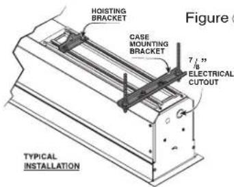
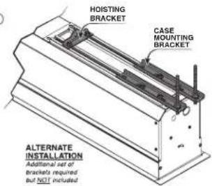
With typical installation, brackets may be angled to meet installation requirements.
③ Installer must insure that fasteners used are of adequate strength and suitable for the mounting surface chosen. Supporting hardware (chains, cables, 38 " rods, etc.) must be essentially vertical.
④ Entire bottom of case must be readily accessible after installation is complete.
⑤ Front, back and top of case must be straight—not forced to warp or bow.
⑥ If case is painted on location, slot on bottom of case should be shielded to protect viewing surface from paint splatters/overspray.
⑦ Do not seal unit in ceiling until electrical connections have been made and screen has been operated successfully.
Suitable for use in environmental air space in accordance with Section 300-22(c) of the National Electrical Code, and Sections 2-128, 12-010(3) and 12-100 of the Canadian Electrical Code, Part 1, CSA C22.1.
Electrical Connections
Screen operates on 110-120V, 60 Hz., 1.1 amp current draw.
Junction box is located just above the bottom access panel at the left end of the screen.
Open the access panel/trap door for access to the junction box cover. (See bottom access panel/trap door opening and closing instructions below).
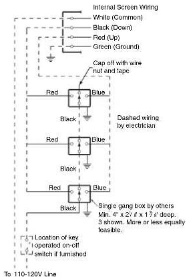
Remove two (2) hex head screws that secure the cover to the junction box to expose the red, black, and white pigtail leads and the green ground wire per wiring diagram on page 3.
If optional low voltage control or video interface control is specified and factory installed, please refer to wiring diagrams on pages 3-4.
Screen is shipped with internal wiring complete and control switch(es) fully boxed. Wire to connect screen to switch(es) and switch(es) to power supply should be furnished by installer. Connections should be made in accordance with attached wiring diagram, and wiring should comply with national and local electrical codes.
All operating switches should be "off" before power is connected.
Bottom Access Panel/Trap Door Opening & Closing
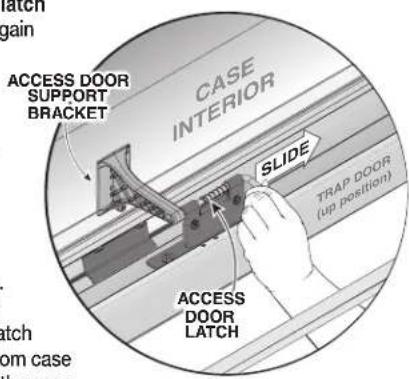
A spring latch near the center of the case and at each end of the trap door holds this
assembly closed. The center latch must be disengaged first. To gain
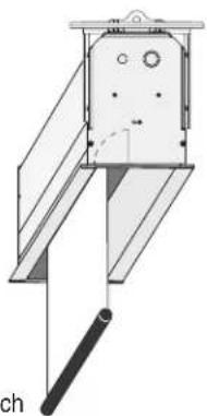
access to inside of screen case, disengage spring latch at center, followed by the latches at each end. To disengage, slide the latch lever towards the center of screen case (see Fig. 2), then pull down slightly on the trap door assembly. The latch levers are somewhat concealed from view.
Locate these with the trap door open by feeling for the vertical latch lever above the door about 3" from case endcaps and near the center of the case.
Figure ②
Please Note: Bracket must be removed in order to move screen into or out of case.
The assembly will swing down, opening about 135°. Pivot the prop arms at each end of the trap door assembly towards the ends of screen case. Prop arms engage with a hole in each endcap to hold the trap door assembly fully open. To close the trap door assembly disengage prop arms from endcaps and pivot these over the access panel. Swing the trap door assembly upward, stopping just before the latch levers hit the bottom flanges of the endcaps (and center of case where appropriate). Pull levers of latches towards center of screen case to allow the trap door assembly to be pivoted to its closed position. Make sure that the spring latch levers engage fully with case endcaps (and center of case where appropriate).
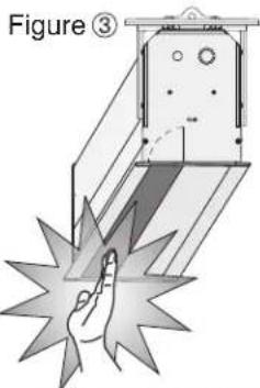
Caution: Beware of pinch points along closure
natural_image
Technical line drawing of a mechanical device with no visible text or symbols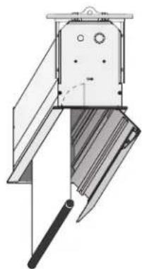
natural_image
Technical line drawing of a mechanical device with no visible text or symbolsIf you have any difficulties installing or servicing your Ultimate Access Projection Screen, call your dealer or Draper, Inc.
Ultimate Access E & V Page 2 of 4
Motorized Roller/Fabric Installation
① The bottom access panel and trap door must be removed first.
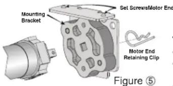
② The motor end mounting bracket has a metal bracket with snap ring for accepting motor head. Back out the two set screws in bracket until they are flush with top side of bracket.
③ To engage the motor end bracket flange above the two channels in the top of the screen housing, rotate the bracket approximately 45☐ counterclockwise to allow the top surface of the motor bracket to rest flat against the top inside of the housing.
④ Rotating the bracket clockwise until it is engaged with the channels, slide it along the length of the housing against the electrical junction box.
⑤ Engage idler end bracket (rectangular mounting pad) in the same manner as motor end bracket and slide it toward the opposite end of the screen housing. Do not tighten set screws on this bracket until the roller/fabric assembly is installed, and centered in case.
Note: Step 6 requires two people to perform safely.
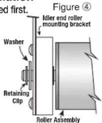
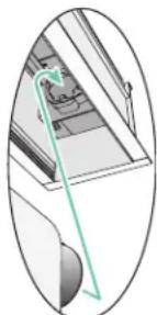
⑥ Locate the black washer and retaining clips attached to the instruction sheet. Raise the roller/fabric assembly up into the screen housing and engage the
head of the motor completely into the motor mounting bracket, making sure the limit switch adjusting knobs are visible from the bottom of the screen housing (see fig. 6). If snap ring is provided, make sure the snap ring engages with the motor. If retaining clip is provided instead, install to lock motor end in place.
⑦ While supporting the idler end of the roller, slide the idler end mounting bracket toward the roller. Insert the roller pin into the nylon bushing on the idler end mounting bracket.
⑧ The roller idler pin needs to go through the idler bracket far enough to allow the washer and retaining clip to be reinstalled on the pin.
CAUTION: Failure to replace the washer and retaining clip could result in the separation of the roller from the brackets.
⑨ The roller/fabric assembly and roller brackets may need to be slid left or right in the mounting channel of case to center fabric within screen case.
⑩ Securely tighten the set screws on roller mounting brackets.
⑪ Connect the electrical plug from the motor to the mating socket on the junction box.
⑫ Reinstall the bottom access panel as previously described.
Motorized Roller/Fabric Removal
Reverse the instructions above "Motorized Roller/Fabric Installation" for removal of the unit.
Operation
When screen is first operated, be cautious! Cycle unit down and up several times to confirm satisfactory operation. Be prepared to cut POWER if necessary. 110-120V SINGLE STATION CONTROL—3-position UP-OFF-DOWN switch permits operation to be stopped at any point. Factory adjusted limit switches automatically stop screen when fully down or fully up.
110-120V MULTIPLE STATION CONTROL—Switches are similar in appearance to 110-120V Single Station Control. Screen stops when switch is released and may be restarted in either direction. Factory adjusted limit switches stop screen automatically when fully up or fully down.
24V CONTROL—Three-button UP-STOP-DOWN switches stop at any point desired, operate in any sequence. Factory adjusted limit switches automatically stop screen when fully up or fully down. Installer should incorporate an all-pole disconnect in the fixed wiring available with RF or IR remote.
110-120V & 12V VIDEO INTERFACE CONTROL—Allows screen to be controlled by trigger signal—when the signal comes on, the screen descends automatically. KEY OPERATED SWITCHING—Two kinds of key-operated switches are optionally available with this unit. ① The key-operated power supply switch controls power to the screen and switches. When it is "off", the switches will not operate screen. Key may be removed from the switch in either "on" or "off" position.
② A three-position key switch permits the screen to be operated directly by key. In this case, the screen's operator must always have a key.
RS232/ETHERNET—Serial communication and network communication optionally available.
natural_image
Diagram of a mechanical assembly with a green line indicating a section or connection (no text or symbols present)Figure ⑥
Limit Adjustments
Please Note: Screen limits are factory set for optimum performance of the screen. A procedure is outlined below for minor tweaks, but any adjustment of these limits may negatively affect the flatness of the screen surface and could also void the warranty. Please check with Draper prior to resetting screen limits.
⚠️CAUTION: Always be prepared to shut screen off manually when new adjustment is being tested. Screen may be severely damaged if viewing surface is allowed to run too far up or too far down.
⚠️CAUTION: Be sure all switches are in “off” position before adjusting limit switches.
The motor limit screws are normally located on the audience left of screen roller.
"DOWN" LIMIT ADJUSTMENT
To Reduce Screen Drop
① Raise screen surface about 1' above desired setting and turn off.
②Turn the WHITE/DOWN limit screw clockwise (three screw turns = 12 roller revolution).
③ Test by running screen down and repeat steps 1 and 2 until desired position is reached.
To Increase Screen Drop
① Run screen to the down limit.
② With the down switch on, turn the WHITE/DOWN limit screw counterclockwise (3 turns of screw equals 12 roller revolution) to increase drop.
③ Test by running screen up about 1' and back down to new down limit.
④ Repeat steps 2 and 3 until desired position is reached.
"UP" LIMIT ADJUSTMENT
Screen is Running Too Far Up
① Lower screen surface about 1' below desired setting and turn off.
② Turn the YELLOW/UP limit screw clockwise (three screw turns = 12 roller revolution).
③ Test by running screen up.
④ Repeat steps 1 through 3 until desired position is reached.
Screen Needs to Run Up More
① Run screen down about 1' and turn off.
② With the up switch on, turn the YELLOW/UP limit screw counterclockwise (three turns of screw = 12 roller revolution).
③ Repeat steps 1 and 2 until desired position is reached.
⚠️ CAUTION: Do NOT allow the dowel to wrap up over the roller when the screen is running up! This could damage the screen.
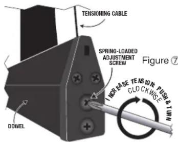
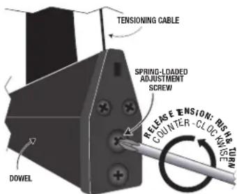
Tab-Tension Adjustment Procedure for Ultimate Access/Series V
Draper's Tab-Tensioning System is factory-set, and under normal circumstances will not require field adjustment. If, however, you notice wrinkles, waves or other indications that the tensioning cables need to be adjusted, follow the procedure below.
① Determine which side requires adjustment.
② Secure dowel with one hand.
③ Using Phillips-head screwdriver, depress spring-loaded adjustment screw and slowly turn CLOCKWISE TO INCREASE tension, or COUNTER-CLOCKWISE TO RELEASE tension. The screw adjusts in 60° turn increments. Adjust only one increment (60° turn) at a time.
④ If problem is not corrected, leave screen in position for 24 hours to allow surface material to stretch into position.
⑤ If problem still is not corrected, repeat steps 2 and 3.
Case Dimensions
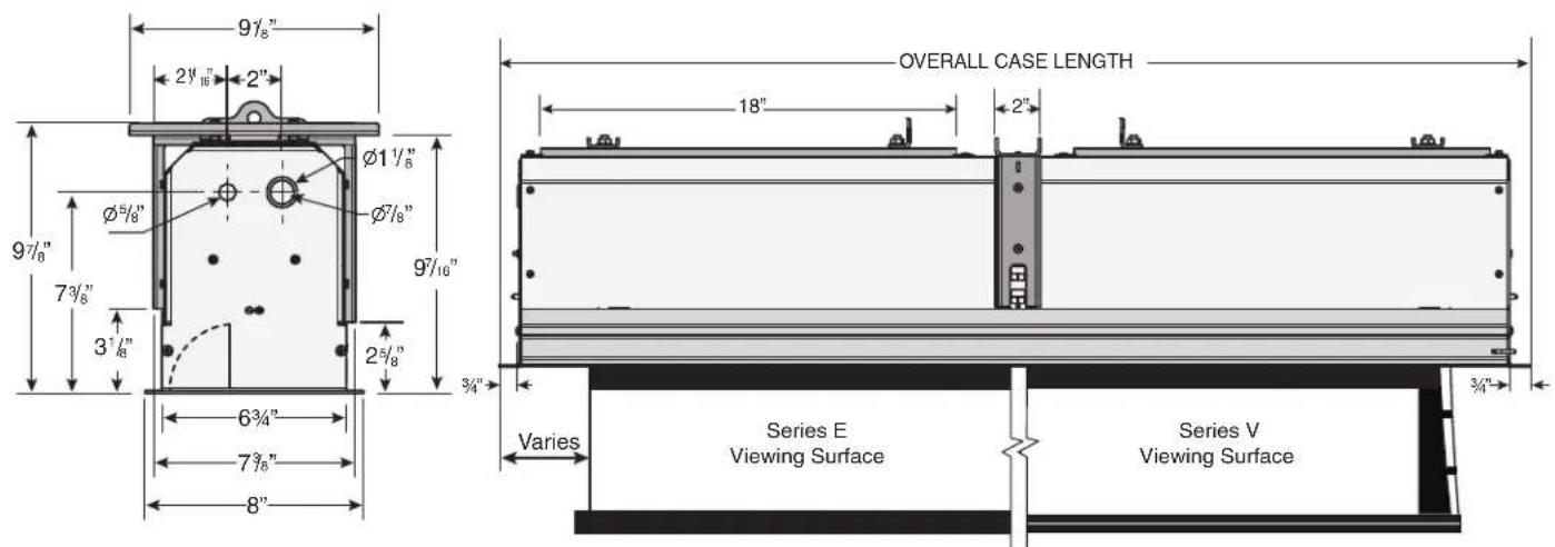
For minimum length of ceiling cutout: subtract 1½" from case length (measured from outer edge of flanges). For minimum width of cutout (front to back): see case width dimensions below.
"Leveling bracket is used to level the case and should NOT be used to support the weight of the unit. The leveling bracket is riveted to the side of the case and remains stationary. Hardware used for leveling provided by others. Leveling bracket is not adjustable.
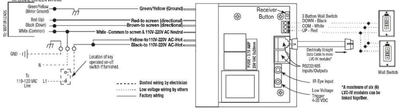
Internal LVC-IV - Single or Multiple Projection Screen Wiring Diagram
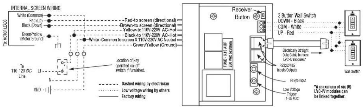
External LVC-IV - Single or Multiple Projection Screen Wiring Diagram
Standard Wiring Diagrams
Single Station Control
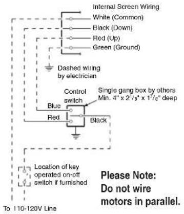
Multiple Station Control