00296 - Vægudtag Vimar - Gratis brugsanvisning og manual
Find enhedens vejledning gratis 00296 Vimar i PDF-format.

Brugerspørgsmål om 00296 Vimar
0 spørgsmål om dette apparat. Besvar dem du kender, eller stil dit eget.
Stil et nyt spørgsmål om dette apparat
Download vejledningen til din Vægudtag i PDF-format gratis! Find din vejledning 00296 - Vimar og tag din elektroniske enhed tilbage i hånden. På denne side er alle dokumenter nødvendige for brugen af din enhed offentliggjort. 00296 af mærket Vimar.
BRUGSANVISNING 00296 Vimar
Two 2P+T 15 A 125 V\~ 60 Hz American standard socket outlets with Ground Fault Circuit Interrupter (GFCI), device complete with mounting frame, to be completed with 3-module Plana or Neve Up cover plates.
DESCRIPTION.
A GFCI receptacle is different from conventional receptacles. In the event of a ground fault, a GFCI will trip and quickly stop the flow of electricity to prevent serious injury.
CHARACTERISTICS.
- Rated voltage 125 V\~60 Hz.
- Rated current corresponding to the socket outlet standard 15 A.
• GFCI Class A (trip 6 mA or more).
Definition of a ground fault:
Instead of following its normal safe path, electricity passes through a person's body to reach the ground. For example, a defective appliance can cause a ground fault. A GFCI receptacle does not protect against circuit overloads, short circuits, or shocks. For example, you can still be shocked if you touch bare wires while standing on a non-conducting surface, such as a wood floor.
TEST YOUR WORK.
Why perform this test?
- If you miswired the GFCI, it may not prevent personal injury or death due to a ground fault. (electrical shock).
- If you mistakenly connect the LINE wires to the LOAD terminals, the GFCI will still operate like an ordinary receptacle, but it will not interrupt a ground fault.
Procedure:
(a) This GFCI is shipped from the factory in the tripped condition and can not be reset until it is wired correctly and power is supplied to the device. Plug a lamp or radio into the GFCI (and leave it plugged in). Turn the power ON at the service panel. Press the RESET button fully, make sure the lamp or radio is ON. If the lamp or radio is still OFF or the RESET button can not be engaged, go to the Troubleshooting section because LINE and LOAD wiring connection have been reversed.
(b) Press the TEST button fully, the GFCI will trip and the lamp or radio will be OFF. To restore power, press the RESET button.
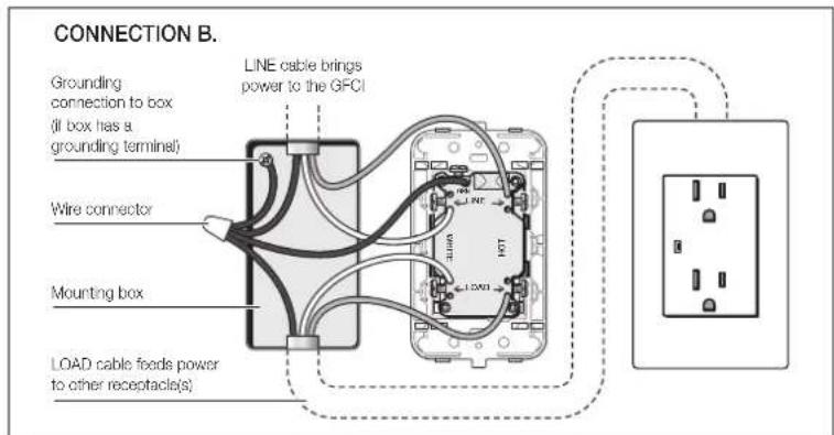
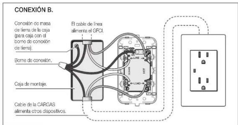
(c) If you installed your GFCI using CONNECTION B, plug a lamp or radio into surrounding receptacles to see which one(s), in addition to the GFCI, lost power when you pressed the TEST button. Do Not plug life saving devices into any of the receptacles that lost power. Place a "GFCI Protected" sticker on every receptacle that lost power. Then press the RESET button to reset the GFCI.
(d) Press the TEST button (then RESET button) every month to assure proper operation. If the GFCI can not be reset, then it must be replaced.
(e) If the GFCI consistently trips it indicates end of life and GFCI must be replaced.
TROUBLESHOOTING.
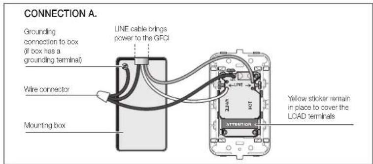
Turn the power OFF and check the wire connections against the appropriate wiring diagram in step CONNECTION A or CONNECTION B. Make sure that there are no loose wires or loose connections. Also, it is possible that you reversed the LINE and LOAD connections. LINE/LOAD reversal will be indicated by power remaining ON at the GFCI after you press the GFCI's TEST button. Reverse the LINE and LOAD connections if necessary. Start the test from the beginning if you rewired any connections to the GFCI.
CAUTION.
To prevent severe shock or electrocution always turn the power OFF at the service panel before working with wiring.
- Use this GFCI receptacle with copper or copper-clad wire. Do not use it with aluminum wire.
- Do not install this GFCI receptacle on a circuit that powers life support equipment because if the GFCI trips it will shut down the equipment.
Must be installed by a skilled person in accordance with national and local electrical codes.
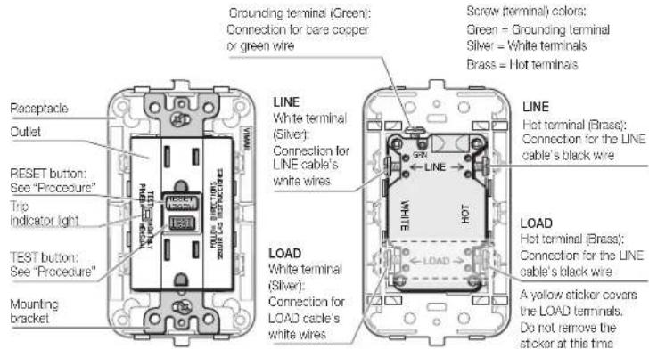
FRONT VIEW BACK VIEW
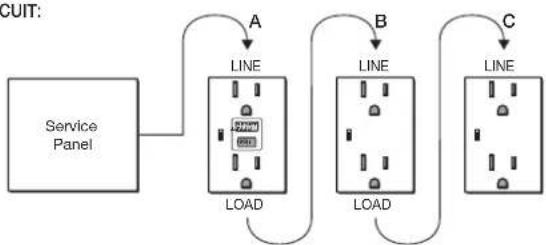
PLACEMENT IN CIRCUIT:
The GFCI's place in the circuit determines if it protects other receptacles in the circuit.
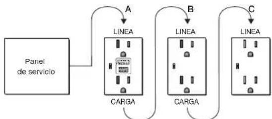
SAMPLE CIRCUIT:
flowchart
graph TD
    A["Service Panel"] --> B["LINE"]
    B --> C["LOAD"]
    C --> D["LINE"]
    D --> E["LOAD"]
    E --> F["LINE"]
    F --> G["LOAD"]
    G --> H["LINE"]
    style A fill:#f9f,stroke:#333
    style B fill:#ccf,stroke:#333
    style C fill:#cfc,stroke:#333
    style D fill:#fcc,stroke:#333
    style E fill:#cff,stroke:#333
    style F fill:#ffc,stroke:#333
    style G fill:#cfc,stroke:#333
Placing the GFCI in position A will also provide protection to "load side" receptacles B and C. On the other hand, placing the GFCI in position C will not provide protection to receptacles A or B. Remember that receptacles A, B and C can be in different rooms.
Dos tomas de corriente 2P+T 15 A 125 V\~ 60 Hz estándar americano con protección diferencial (GFCI), dispositivo completo de soporte; se completan con placas 3 módulos Plana o Neve Up.
DEFINICIÓN.
Un receptáculo GFCI es diferente a los receptáculos convencionales. En caso de fallo de conexión a tierra, un GFCI se desconectará y detendrá rápidamente el flujo eléctrico para no causar daños.
CARACTERÍSTICAS.
- Tensión nominal 125 V\~ 60 Hz.
- Corriente nominal correspondiente a la toma estándar 15 A.
- Clase A GFCI (trip 6 mA o más).
Definición de un fallo de conexión a tierra:
La electricidad, en vez de seguir su camino normal y seguro, pasa a través del cuerpo de una persona para llegar al suelo. Por ejemplo, un aparato defectuoso puede provocar un fallo de conexión a tierra. Un receptáculo GFCI no protege frente a sobrecargas, cortocircuitos o electrocuciones. Por ejemplo, uno puede suñir una descarga si toca los cables descubiertos mientras está sobre una superficie no-conductora, como un suelo de madera.
PRUEBE SU TRABAJO.
Por qué realizar esta prueba?
- Si no ha cableado correctamente el GFCI, puede que no impida daños personales o fallecimientos debido a un fallo de conexión a tierra (descarga eléctrica).
- Si se conecta, erróneamente la línea principal al borne de carga, el GFCI operará como un simple interruptor, todavía no interrumpirá un fallo de conexión a tierra.
Procedimiento:
(a) Este GFCI se envía desconectado de fábrica y no puede ser reiniciado hasta que se cablea correctamente y se conecta el aparato a la red eléctrica. Enchufe una lámpara o una radio al GFCI (y déjelo enchufado). Conecte la potencia en el panel de servicio. Pulse a fondo el botón de reinicio (RESET) asegurándose de que la lámpara o la radio esté encencida. Si la lámpara o la radio está aún apagada o no se puede apretar fondo el botón de reinicio, consulte el apartado de Solución de Problemas porque se han invertido los cables de conexión de LÍNEA y CARGA.
(b) Pulse a fondo el botón de prueba (TEST). El GFCI se desconectará y se apagará la lámpara o la radio. Para restaurar la potencia pulse el botón RESET.
(c) Si ha instalado el GFCI utilizando CONNEXIÓN B, enchufe una lámpara o radio a los receptáculos circundantes para ver cuáles perdieron potencia, además del GFCI, cuando pulsó el botón TEST. No enchufe dispositivos de supervivencia a ninguno de los receptáculos que perdieron potencia. Coloque una pegatina que indique "Protegido por GFCI" en todos los receptáculos que perdieron potencia. Luego, pulse el botón RESET para reiniciar el GFCI.
(d) Pulse el botón TEST (y, después, RESET) cada mes para garantizar un buen funcionamiento. Si no se puede reiniciar el GFCI, deberá cambiarlo.
(e) Si el GFCI se activa continuamente, indica el fin de la vida del GFCI y debe ser reemplazado.
SOLUCIÓN DE PROBLEMAS.
Desconecte la electricidad y compruebe las conexiones de cableado comparando con el diagrama de cableado adecuado en CONNEXIÓN A o CONNEXIÓN B. Asegúrese de que no haya cables o conexiones sueitos. También, es posible que usted invirtiera las conexiones de la LINEA y la CARGA. La reversión de la LINEA/CARGA será indicada aprietando el botón TEST, la alimentación se queda en el estrado de ON. Invertir las conexiones de la LINEA y la CARGA si necesario. Empiece la prueba desde el principio si ha vuelto a cablear alguna conexión del CFCI.
CUIDADO.
Para evitar descargas graves o electrocuciones, antes de trabajar con el cableado, deberá APAGAR el receptáculo GFCI en el panel de servicio.
- Utilice este receptáculo GFCI con cables de cobre o con recubrimiento de cobre. No lo utilice con cables de aluminio.
- No instale este receptáculo GFCI en un circuito que alimente equipos de supervivencia porque, si el GFCI se desconecta, se apagará el equipo.
Deberá ser instalado por una persona cualificada de acuerdo con los códigos de electricidad nacionales y locales.
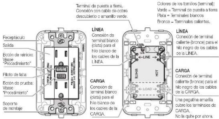
VISTA DELANTERA VISTA POSTERIOR
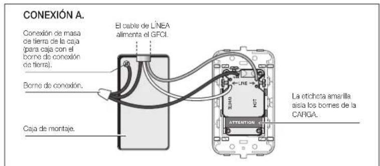
COLOCACIÓN EN EL CIRCUITO:
El lugar que ocupa el GFCI en el circuito determina si protege a otros receptáculos del circuito o no.
CIRCUITO DE MUESTRA:
flowchart
graph TD
    A["Panel de servicio"] --> B["LINEA"]
    B --> C["CARGA"]
    C --> D["LINEA"]
    D --> E["CARGA"]
    E --> F["LINEA"]
Si se coloca el GFCI en la posición A, también protegerá a los receptáculos de "baja carga" B y C. Sin embargo, si se coloca el GFCI en la posición C, no protegerá a los receptáculos A o B. recuerde que los receptáculos A, B o C pueden encontrarse en salas diferentes.