DSZ15WDM-3x5A - Måling Eltako - Gratis brugsanvisning og manual
Find enhedens vejledning gratis DSZ15WDM-3x5A Eltako i PDF-format.

Brugerspørgsmål om DSZ15WDM-3x5A Eltako
0 spørgsmål om dette apparat. Besvar dem du kender, eller stil dit eget.
Stil et nyt spørgsmål om dette apparat
Download vejledningen til din Måling i PDF-format gratis! Find din vejledning DSZ15WDM-3x5A - Eltako og tag din elektroniske enhed tilbage i hånden. På denne side er alle dokumenter nødvendige for brugen af din enhed offentliggjort. DSZ15WDM-3x5A af mærket Eltako.
BRUGSANVISNING DSZ15WDM-3x5A Eltako
M-bus three-phase meter for use with CT DSZ15WDM-3x5A with display and MID approval
Only skilled electricians may install this electrical equipment otherwise there is the risk of fire or electric shock!
Temperature at mounting location: -25°C up to +55°C.
Storage temperature: -25°C up to +70°C.
Relative humidity: annual average value <75%.
CT operated energy meter with settable CT ratio and MID. Maximum current 3x5 A. Standby loss 0.5 watt per path only.
Modular device for DIN-EN 60715 TH35 rail mounting.
4 modules = 70 mm wide and 58 mm deep.
Accuracy class B (1%). With M-bus interface.
This three-phase meter measures active energy by means of the currents flowing between inputs and outputs. The internal power consumption of 0.5 watt active power per path is neither metered nor indicated.
1, 2 or 3 converters with secondary currents of up to 5 A can be connected.
The inrush current is 10 mA. The N terminal must always be connected.
The consumption value is stored in non-volatile memory and is displayed again immediately after a power failure.
The 7 segment LC display is also legible twice within a period of 2 weeks without power supply.
Power consumption is indicated by an LED flashing at a rate of 10 times per KWh.
On the right next to the display are the MODE and SELECT buttons to browse through the menu. First the background lighting switches on. Then the total active energy, the active energy of the resettable memory and the instantaneous values of power, voltage and current are displayed for each outer conductor.
The CT ratio can also be set. It is set to 5:5 at the factory and blocked with a bridge over the terminals which are marked with 'JUMPER'. To adjust the CT ratio to the installed transformer remove the bridge and reset the energy meter according to the operation manual. Then block it again with the bridge. Adjustable current transformer ratios: 5:5, 50:5, 100:5, 150:5, 200:5, 250:5, 300:5, 400:5, 500:5, 600:5, 750:5, 1000:5, 1250:5 and 1500:5.
Error message (false)
If there is no outer conductor of the current direction is incorrect, false' and the related outer conductor are indicated in the display.
M-bus data transfer
■ On read-out all values are transferred in a telegram.
■ The following telegrams are supported:
- Initialisation: SND_NKE Reply: ACK
- Read out meter: REQ_UD2 Reply: RSP_UD
- Change primary address: SND_UD Reply: ACK
- Reset RS1: SND_UD Reply: ACK
- Slave selection for the secondary address Reply: ACK
■ The device does not reply to unknown requests
■ The transfer rate is detected automatically
■ The device has a voltage monitor. In case of voltage loss, all registers are saved in the EEPROM.
Changing the M-bus primary address:
To change the M-bus primary address, hold down SELECT for 3 s. In the menu that appears, press MODE to increment the address by 10. Press SELECT to increment by 1. When the required primary address is set, wait until the main menu reappears.
Secondary address:
It is possible to communicate with the energy meter according to the standard EN13757 with help of the secondary address.
■ The use of wildcards is possible.
Detailed information are available in the operating manuals at www.eltako.com
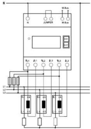
Important! Before working on the current transformers disconnect the voltage paths of the energy meters.
Typical connection:
4-wire-connection 3x230/400 V
The secondary current converter terminals on the mains side must be connected to the outer conductors measured. These connections for the meter power supply must be protected according to local installation regulations.
Technical data
| Rated voltage, extended range 3x230/400 V, 50 Hz, -20%/+15% | |
| Reference current I_ref (Limiting current I_max ) 3x0.05 - 5(6)A | |
| Internal consumption active power 0.5 W per path | |
| Display | LC display 7 digits, therefrom 1 digit after the decimal point |
| Accuracy class ±1% | B |
| Inrush current according to accuracy class B | 10 mA |
| Operating temperature | -25/+55°C |
| Bus system | M-Bus |
| Bus length | According to M-bus specifications |
| Transfer rates | 300, 2400, 9600 baud. |
| Response time (system response time) | Write up to 60 msRead up to 60 ms |
| Terminal cover sealable | Terminal cover claps |
| Protection degree | IP50 for mounting in distribution cabines with protection class IP51 |
| Maximum conductor cross section11 | N and L terminals 16 mm2, M-Bus terminals and jumper terminals 6 mm2 |
| Recommended torque21 | L- and N terminals 1,5 Nm (max. 2,0 Nm) |
| M-Bus terminals and jumper terminals 0,8Nm (max. 1,2 Nm) | |
| EC type examination certifi cate | 0120/SGS0314 |
| The energy meter is used indoors. | |
| Mechanical environmental conditions | class M1 |
| Electromagnetic environmental conditions | class E2 |
The carrying capacity of cables and wires is defined in DIN VDE 0298-4.
21 The torques for screw terminals are mentioned in DIN EN 60999-1.
To avoid damages at the energy meter, the recommended torque values for each terminal must not be exceeded!
Menu guidance
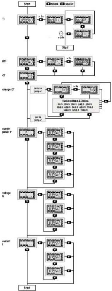
flowchart
graph TD
    A["Start"] --> B["MODE SELECT"]
    B --> C["T1"]
    C --> D[">3s MODE"]
    D --> E[">20s MODE"]
    E --> F["Start"]
    G["RSI"] --> H[">3s MODE"]
    H --> I[">20s MODE"]
    I --> J["Start"]
    K["CT"] --> L[">3s MODE"]
    L --> M[">20s MODE"]
    M --> N["Start"]
    O["change CT"] --> P["remove jumper"]
    P --> Q[">3s MODE"]
    Q --> R[">20s MODE"]
    R --> S["Start"]
    T["current power P"] --> U[">3s MODE"]
    U --> V[">20s MODE"]
    V --> W[">20s MODE"]
    W --> X["Start"]
    Y["voltage U"] --> Z[">3s MODE"]
    Z --> AA[">20s MODE"]
    AA --> AB[">20s MODE"]
    AB --> AC["Start"]
    AD["current I"] --> AE[">3s MODE"]
    AE --> AF[">20s MODE"]
    AF --> AG[">20s MODE"]
    AG --> AH["Start"]
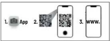
Manuals and documents in further languages

http://eltako.com/redirect/DSZ15WDM-3*5A_MID
EC DECLARATION OF CONFORMITY
| Product | Calibrated electronic M-bus three-phase energy meter with MID approvalCT operated energy meter with settable CT ratio |
| Type designation | DSZ15WDM-3x5A |
| EC-type examination certificate | 0120/SGS0314 |
| The manufacturer herewith declares, on his own responsibility that the designated products which this certificate refers to, are in accordance with the following harmonized standards or normative documents as well as with the following Directives of the European Parliament and of the Council ( relevant version ): | |
| DIN EN 50470 | part 1: 2019-08 and part 3: 2020-03 ( electronic meters ) |
| 2014 / 32 / EU | measuring instruments |
| 2014 / 30 / EU | electromagnetic compatibility |
| 2011 / 65 / EU | restriction of the use of certain hazardous substances ( RoHS Directive ) |
| The designated products are placed on the market by ELTAKO GmbH ,Hofener Straße 54 , 70736 Fellbach, Germany. | |
| Notified body | SGS Fimko OY, No. 0598Takomotie 8, FI-00380 Helsinki, Finland |
| Manufacturer | Shenzhen Chuangren Technology Co. Ltd.Building 33. No.3 Industrial Area, Mashantou, Gongming Street.New Guangming District, Shenzhen City, Guangdong Province, 518106, China |
| Place. Date | Shenzhen, 25 February 2021 |
| Signature | |
| This declaration proves the compliance with the above-mentioned EC Directives but it does not include any assurance of properties.Security advices of the provided product information have to be noticed. | |
Must be kept for later use!
We recommend the housing for operating instructions GBA14.
Eltako GmbH
D-70736 Fellbach
Technical Support English:
+49 711 94350025
technical-support@eltako.de
eltako.com
42/2022 Subject to change without notice.