JK201SPD - Overspændingsbeskytter HAGER - Gratis brugsanvisning og manual
Find enhedens vejledning gratis JK201SPD HAGER i PDF-format.


Brugerspørgsmål om JK201SPD HAGER
0 spørgsmål om dette apparat. Besvar dem du kender, eller stil dit eget.
Stil et nyt spørgsmål om dette apparat
Download vejledningen til din Overspændingsbeskytter i PDF-format gratis! Find din vejledning JK201SPD - HAGER og tag din elektroniske enhed tilbage i hånden. På denne side er alle dokumenter nødvendige for brugen af din enhed offentliggjort. JK201SPD af mærket HAGER.
BRUGSANVISNING JK201SPD HAGER
JK201SPD & JKD201SPD
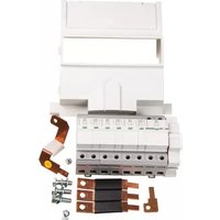
Surge Protection Kit
Type 1 + 2 Surge Protection Kit for Hager 250A TP&N Distribution Boards to aid compliance with 18 ^th Edition BS 7671.
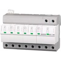
- Plug-in lightning and surge arrester combination, in accordance with Type 1+2/Class 1+2, for 3-phase power supply networks, with separate N and PE (L 1, L2, L3, PE, N).
Green = Healthy, Red = Replace
- Directly coordinated combination of type 1 spark gap without line follow current and type 2 varistor arrester
- Particularly suitable for maximum protection of sensitive devices in harsh environments
- High continuous voltage of 350 V AC for 230/400 V AC networks with high voltage fluctuations
- Pluggable
- Low voltage protection level of 1.5 kV
- Optical, mechanical status indicator
- Floating remote indication contact
Product Description
A Surge protection device (SPD) kit specifically developed for Hager standard 250A TPN (Type B) Distribution boards. Developed to ensure optimal performance of SPD technology within Hager distribution boards. SPD is CT2 type to ensure compatibility with all common UK Earthing arrangements e.g. TN-C-S (PME), TN-S and TT earthing arrangements. This is an IEC Type 1 + 2 SPD for 3 – phase power supply networks. A type 1 SPD is generally used in the primary distribution board.
This SPD kit fits within the standard distribution board. Line, Neutral and Earth connections are via copper links, minimising SPD conductor losses, maximising the effective performance of the SPD ( U_p effective).
Key Specifications
- Power Supply System -TN / TT
- Requirement class -SPD class II acc. to IEC 61643-11 2011; SPD Type 1 acc. to EN 61643-11 2012
- Max. continuous operating voltage Uc -L-N: 275 V a.c. / N-PE: 260 V a.c.
- Nominal voltage U n -240/415 V AC 50/60 Hz
- Impulse discharge current (10/350) s (L-N/L-PE), peak current value I_Imp 25 kA
- Impulse discharge current (10/350) s (N-PE), peak current value I_Imp 100 kA
- Nominal discharge current I n (8/20) microseconds 20 kA
- Max. discharge current | max (8/20) microseconds 40 kA
SPD Protection level U_p -L-N: <1.35 kV/N-PE: <1.5 kV
Solution Protection level U_p effective (measured at the main busbars on the TPN board) -L-N: <1.5kV/ N-PE: <1.5kV
Short-circuit current rating |SCCR -25kA
Degree of protection - IP20
Tightening torque - see installation instructions.
Dimensional Drawing


Circuit Diagram

General Data
| Standards/regulations IEC 61643-11 2011 EN 61643-11 2012 | |
| IEC test classification | I + II |
| EN type | T1 + T2 |
| Mode of protection L-N | L-PEN-PE |
| Mounting type DIN rail: 35 mm | |
| Degree of pollution 2 | |
| Overvoltage category III | |
| Degree of protection IP20 | |
| Shock (operation) | 30g (Half-sine / 11 ms / 3x ±X, ±Y, ±Z) |
| Vibration (operation) | 5g (5 - 500 Hz/ 2.5 h / X, Y, Z) |
| Ambient temperature (operation) -40 °C ... 80 °C | |
| Ambient temperature (storage/transport) Permissible humidity (operation) | -40 °C ... 80 °C |
Electrical Data
| Nominal voltage U_n | 240 / 415 V AC (TN / TT) |
| Nominal frequency f_n | 50 Hz (60 Hz) |
| Maximum continuous operating voltage Uc (L-N) | 350 V AC |
| Maximum continuous operating voltage Uc (L-PE) | 350 V AC |
| Maximum continuous operating voltage Uc (N-PE) 260V AC | |
| Residual current I_PE | ≤ 1 uA |
| Standby power consumption Pc ≤ 360 mVA | |
| Impulse discharge current (10/350) μs (L-N/L-PE), peak current value I_mp | 25kA |
| Impulse discharge current (10/350) μs (N-PE), peak current value I_mp | 100kA |
| Nominal discharge current In (8/20) μs | 25kA |
| Maximum discharge current Imax (8/20) μs 40kA | |
| Follow current interrupt rating I_f (N-PE) 100A | |
| Short-circuit current rating IsccR | 25kA |
| Voltage protection level Up (L-N) | ≤ 1.5kV |
| Voltage protection level Up (L-PE) | ≤ 2.2 kV |
| Voltage protection level UP (N-PE) | ≤ 1.5kV |
| Max. backup fuse | 315 A (gG) |
| Max. backup fuse with V-type through wiring | 125 A (gG) |


Mærke : HAGER
Model : JK201SPD
Kategori : Overspændingsbeskytter