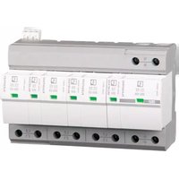
JN201SPD - Overspændingsbeskytter HAGER - Gratis brugsanvisning og manual
Find enhedens vejledning gratis JN201SPD HAGER i PDF-format.


Brugerspørgsmål om JN201SPD HAGER
0 spørgsmål om dette apparat. Besvar dem du kender, eller stil dit eget.
Stil et nyt spørgsmål om dette apparat
Download vejledningen til din Overspændingsbeskytter i PDF-format gratis! Find din vejledning JN201SPD - HAGER og tag din elektroniske enhed tilbage i hånden. På denne side er alle dokumenter nødvendige for brugen af din enhed offentliggjort. JN201SPD af mærket HAGER.
BRUGSANVISNING JN201SPD HAGER
natural_image
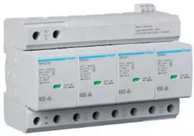
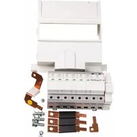
Exterior view of a three-phase power distribution protection kit (no visible text or labels)JN201SPD
User instructions
Parts list:
- Type I+II Surge arrestor x 1
- Neutral Cable x 1
- L1/L2/L3 Phase cables x 3
- SPD Mounting bracket (Dinrail) x 1
- Earth Link x 1
- Hex head high torque screws x 4
- M8 x 16mm Hex head screw x 1
- M8 Plain washer x 1
Surge Protection Kit JN 250A Type I+II
natural_image
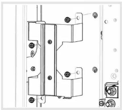
Technical line drawing of a mechanical assembly with mounting holes and internal components (no text or symbols)Fix the din rail bracket to the left hand side of the enclosure with 4 Hex head high torque screws.
'Always install the chosen Incomer first'.

natural_image
Technical line drawing of a mechanical or electrical component with no visible text, numbers, or symbols.Clip the Surge protection device to the dinrail with the neutral to the left. Insert the copper earth link into the first earth terminal on the SPD and torque to 3.8Nm then use the M8 Screw with plain washer to secure to the chassis to 13Nm.

natural_image
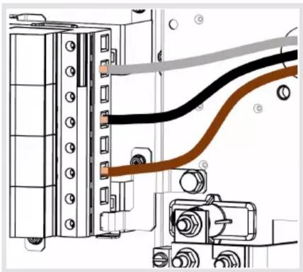
Diagram of an electronic device showing a cable inserted into a connector panel (no text or labels visible)Connect to the neutral cable to the SPD and torque to 3.8Nm, Then connect the ring terminal to the neutral assembly as shown above and Torque to 13Nm.
natural_image
Technical diagram of a mechanical or electrical component with labeled parts (no readable text or symbols)Feed the L1/L2/L3 cable through the bushed hole in the chassis and terminate into the Surge protection device at 3.8Nm.

natural_image
Pure electrical circuit lines without any symbolsTerminate the ring terminals of the phase links L1/L2/L3 to the top of the incomer phase links using the existing bolts provided with the chosen incomer and torque to 13Nm.
The device may only be connected and installed by an electrically skilled person. National standards and safety regulations must be observed.
The surge protection device sits behind the clear blank provided with the chosen panelboard.
The device must be checked for external damage prior to installation. If any damage or other defects are detected in this check, the device must not be installed.
Its use is only permitted within the limits shown and stated in the installation instructions.
Opening or otherwise tampering with the device invalidates the warranty.



Mærke : HAGER
Model : JN201SPD
Kategori : Overspændingsbeskytter