DE-1123EGA - Projektor OPTOMA - Bezplatný návod k obsluze
Najděte návod k zařízení zdarma DE-1123EGA OPTOMA ve formátu PDF.

| Typ produktu | DLP projektor |
| Zobrazovací technologie | Jednotný 0,55" DMD |
| Rozlišení | 1024 x 768 (XGA) |
| Jas | 3000 ANSI lumenů |
| Kontrastní poměr | 20 000:1 |
| Typ lampy | 190W P-VIP |
| Životnost lampy | Až 10 000 hodin (Eco režim) |
| Vstupy | HDMI 1.4a, VGA, kompozitní video, audio 3,5mm |
| Výstupy | VGA, audio 3,5mm |
| Zvuk | 2W mono reproduktor |
| Poměr zoomu | 1,1x manuální |
| Korekce lichoběžníkového zkreslení | ±40° vertikální |
| Projekční vzdálenost | 1,2 – 11,8 m |
| Velikost obrazu | 30 až 300 palců |
| Rozměry (Š x H x V) | 300 x 220 x 100 mm |
| Hmotnost | 2,5 kg |
| Spotřeba energie | 250W (max.), <0,5W v pohotovostním režimu |
| Napájení | AC 100–240V, 50/60 Hz |
| Hlučnost provozu | 30 dB (Eco režim) |
| Provozní teplota | 5°C – 40°C |
| Výměna lampy | Vyměnitelná uživatelem, díl SP.8GP01.001 |
| Čištění filtru | Každých 500 hodin, přístupný filtr |
| Bezpečnostní prvky | Kensington zámek, automatické vypnutí |
| Součástí balení | Napájecí kabel, VGA kabel, dálkové ovládání, uživatelská příručka |
Často kladené otázky - DE-1123EGA OPTOMA
Dotazy uživatelů ohledně DE-1123EGA OPTOMA
0 otázka o tomto zařízení. Odpovězte na ty, které znáte, nebo položte vlastní.
Položte novou otázku o tomto zařízení
Stáhněte si návod pro váš Projektor ve formátu PDF zdarma! Najděte svůj návod DE-1123EGA - OPTOMA a vezměte svůj elektronický přístroj zpět do rukou. Na této stránce jsou zveřejněny všechny dokumenty potřebné k používání vašeho zařízení. DE-1123EGA značky OPTOMA.
NÁVOD K OBSLUZE DE-1123EGA OPTOMA
Optoma
natural_image
Line drawing of a flat-screen projector with a cable and connector (no text or symbols)Optoma Europe Ltd.
42 Caxton Way
The Watford Business Park
Watford Hertfordshire WD18 8QZ UK
Tel: +44 (0) 1923 691 800
Fax: +44 (0) 1923 691 888
www.optoma.co.uk

ISO9001:2000 International Certification
Thank you for purchasing a Optoma projection screen.
Before use, please read instructions carefully. After installation, store instructions for future reference.
Description
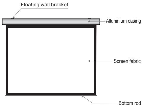
text_image
Floating wall bracket Allunium casing Screen fabric Bottom rod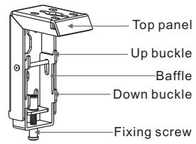
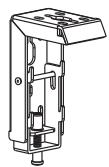
text_image
Top panel Up buckle Baffle Down buckle Fixing screwAccessaries
■ Floating wall bracket (2pcs)
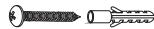
■ 5 × 40mm Tapping screw & cap (8sets)
■ M5x10 Screw (6pcs)

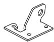
■ Ceiling hanger (2pcs)
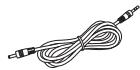
■ Trigger line (1pc)
■ Externnal IR Receiver (1pc)
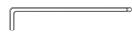
■ Allen key (1pc)
■ Remote Controller (1pc)

■ Instruction manual (1pc)
Motorized Screen Power Specifications
| Voltage | Frequency | Watts | Application |
| 230V/120V/100V | 50Hz/60Hz | 90W/80W | Applies up to 120" motorized screens |
Warnings
- The ceiling or wall used for fixture installation must be secure to prevent the screens from falling.
■ While installing electrical motors, please hire professionals or your local dealer to ensure safety. A misconnection may lead to fire or leaks.
■ Make sure the Fixing screw be fastened when using the wall bracket, to avoid any damage. - Keep all infrared wireless products away from fluorescent lighting as it may cause malfunctions.
- Please read the following as any damage to the screen surface will affect the quality of the picture:
- Avoid contact or touching the screen surface as it may cause scratches or tears.
- Do not write or draw on the surface.
- Clean the screen with a soft cloth and lukewarm water. Do not use any detergent or cleaning products.
- Roll up the screen after every use. Ensure that the screen is level when installing; do not pull on the sides or fold the screen.
■ To prevent unnecessary damage, the operating and maintenance of the screen should be done by adults. - Roll up the screen after every use. Ensure that the screen is level when installing; do not pull on the sides or fold the screen.
- To prevent unnecessary damage, the operating and maintenance of the screen should be done by adults.
 | Ignoring the safety warnings may lead to injuries and/or damaging the product. |  | Fixtures should be installed in a secure place to avoid accidents or the screen falling. |
 | Do not connect any electrical attachments or remote controls. |  | Roll up the screen after every use.Leaving it hanging for a long period of time may cause the fabric to loosen. |
| [WKBX] | Please contact your local dealer for repairs or maintenance. Please contact our company if you have any further questions. Avoid taking apart the fixtures yourself. Loose parts may cause the screen to fall. |  | Refrain from hanging anything on the screen as it may cause the screen to fall. |
Do not take apart and replace with unknown parts. If there are any problems, please contact your local dealer. Product specifications are subject to change.
Installation
Take out all the parts from the packaging and follow the accessagires guideline to ensure you have all parts.
There are three installation measures for this product, namely wall mounting, ceiling mounting and ceiling hang. The installed distance can be changeable up to your needs via adjusting the slipper block, while the ideal position is the mounting bracket is at its nearest point to the endcap, which can reduce unnecessary vibration or noise.
Floating wall bracket installation
- Choose screws for mounting according to wall material. ( Tips: Wood screws for wood wall, and Tapping screws for concrete wall.)
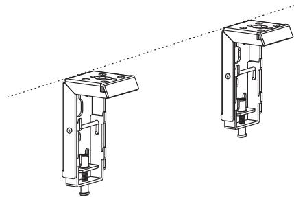
- Mount the brackets onto the wall, assuring they are at the horizontal level. (Tips: draw an erasable level line when mounting the brackets) (Figure 1) Here below are the details:
natural_image
Technical line drawing of two mechanical components with mounting holes and housing (no text or symbols)Figure 1
Installation Steps
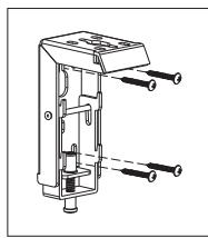
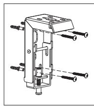
a) Wood wall and ceiling installation: Drill in the 5 × 40 screws through the appropriate holes in the bracket (Figure 2-3).
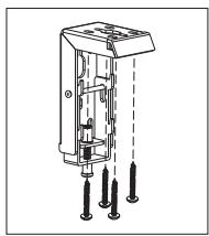
b) Drywall and ceiling and installation: Install the anchors and drill in the 5 x 40 screws into the appropriate bracket holes. (Figure 4-5).
Wood wall installation
natural_image
Technical line drawing of a mechanical component with multiple ports and shafts (no text or symbols)Figure 2
Wood ceiling installation
natural_image
Technical line drawing of a mechanical device with multiple pins and mounting holes (no text or symbols)Figure 3
Concrete wall installation
natural_image
Technical diagram of a mechanical assembly with multiple bolts and housing (no text or labels)Figure 4
Concrete ceiling installation
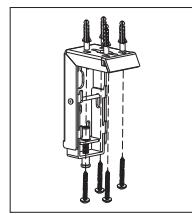
natural_image
Technical line drawing of a mechanical device with multiple pins and shafts (no text or symbols)Figure 5
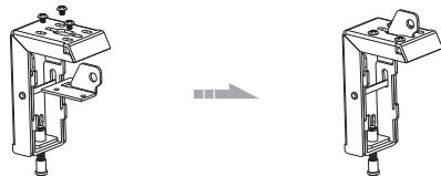
- Loose the Fixing screw to lower down the Baffle all the way. (Figure 6-7)
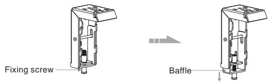
text_image
Fixing screw BaffleFigure 6
Figure 7
- When mounting the screen onto Floating wall brackets, make sure the Up groove and the Down groove on the housing match with the Up buckle and the Down buckle on the bracket separately. ( Figure 8-9 ).
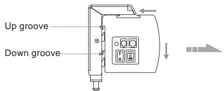
text_image
Up groove Down grooveFigure 8
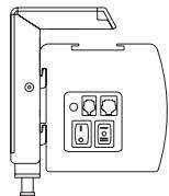
Figure 9
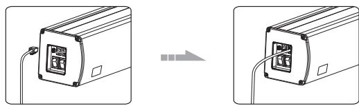
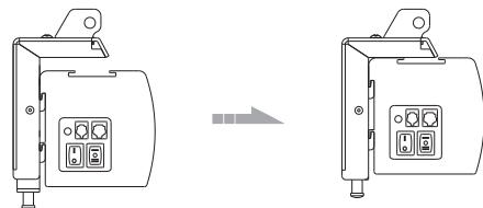
- Fasten the Fixing screw on the bracket, to fix housing tightly onto the brackets. (Figure 10-11)
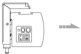
natural_image
Line drawing of a device with control panel and indicator lights (no text or symbols)Figure 10
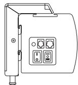
Figure 11
Attention:
Please make sure there is no dust or dirt on the fabric surface before rolling it back to the casing
The recommended working time is less than 50 seconds. The motor will enter overheating protection status and stop working for every continuous 4 minutes operation, user would need to wait for a while until the motor cool down before operating again.
There is no lube needed for the motor. Please be noticed that the appropriate setting is optimized which requires no further adjustment, please consult the after sales team before adjusting the limits.
How to use Trigger Control:
- Insert one end of the signal cable into the Trigger jack of the handle controller, and the other end into the DC5V-12V output hole of the projector (Figure 22-23).
- Press the control switch of the handle controller to the "-" location.
- Switch Manual/Remote Control Button to position "0" (manual stalls).
- When running the projector, the screen will spread the fabric automatic by synchronous; when closing the projector, screen will be back automatic by synchronous too.
- If you don't need to use the trigger control, please draw off the burst line directly, then control it by your hand.
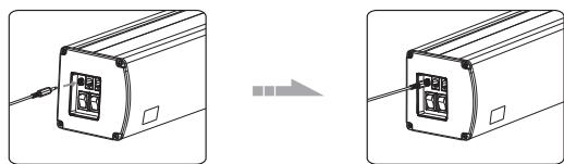
natural_image
Diagram showing two identical devices with a cable inserted, connected by a wire to a separate device (no text or symbols present)Figure 22
Figure 23
How to use External Control (Central Controller or RS232/USB):
- Turn the manual/IR remote control switch to position "0" (remote control stalls)
- Plug one side of the signal cord into the computer output jack at left side of the screen's end cap, the other side of the singal cord to plug into the jack of Central Controller or computer RS232/USB (Note: in order to use RS232
Control, an Adapter is necessary to be connected with, the Adapter is not in the accessory package)(Figure 24-25), and then you can control up/pause/down of the screen via Central Controller or computer.
natural_image
Diagram showing two views of a device with ports and cables, no text or symbols presentFigure 24
Figure 25
How to use IR Remote Control:
- Turn the manual/IR remote control switch to position "0" (remote control stalls)
- When there's nothing to keep our of the IR window, you can use the controller to control up/pause/down of the screen (Figure 26).
- For hidden installation or IR window is being kept out by something, please take out the IR Receiver Head and plug it to the revelant hole, and then install it at the position where IR signal is available (Figure 27)
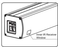
Figure 26
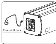
Figure 27
Ceiling hang installation
To choose the tapping screws with hanger or other screws with hanger (unprovided) according to ceiling material. (Tips: Wood screws 5× 40 for wook ceiling and tapping screws for concrete wall.)
- To drill two same holes with an electric drill horizontally with wall, then fasten hangers(unprovided) onto the ceiling. (Figure 12)
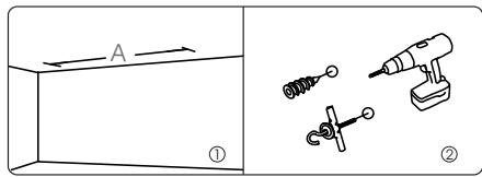
text_image
A ① ②Figure 12
- Use M5 x 10 screws in the accessory package to fix the ceiling hanger into wall bracket, make sure the tightening screws on wall bracket are fixed tightly. (Figure 13-14)
natural_image
Technical line drawing of two mechanical components with mounting holes and a right-angle view (no text or symbols)Figure 13
Figure 14
- After fix the ceiling hanger, make sure the up groove and the down groove on the housing match with Up button and Down button on the bracket separately and fasten the fixing screw on the bracket, to fix housing tightly onto the brackets.( Figure 15-16)
natural_image
Technical line drawing of two electronic device modules with control panel and indicator lights (no text or symbols)Figure 15
Figure 16
- After finished step 2 and step 3, check whether wall bracket fix on the housing of screen tightly then you can hang the screen according to the figure 17.
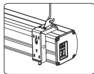
Figure 17
Instructions
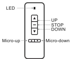
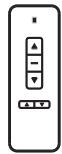
text_image
LED UP STOP DOWN Micro-up Micro-downModel: AC127
Button Function and Operation Instruction :
- Press UP button to lift the screen
- Press STOP button to stop the screen
- Press DOWN button to lower the screen
- Press MICRO-UP button to retract the screen in small increments(150ms for each movement)
- Press MICRO-DOWN button to lower the screen in small increments (150ms for each movement)
Cautions:
- The minimum distance between Controller and Receiver: 50cm
- Workable within 8m in horizontal direction from the Receiver to the Controller
3.Do not cover the Controller's launching port while operation - Strictly banoperation in wet or high temperature environment.
- Replacing batteries when the signal is faint or no signal.
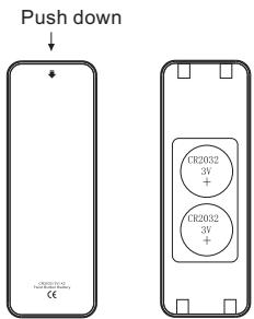
- Batteries for the Controller: 2 units CR2032 button cells.
text_image
Push down CE CR2032 3V + CR2032 3V + 1978145 1978145 1978145Batteries Installation Instruction:
When the signal of the Controller is faint, please replace the batteries as follow steps:
- Reverse Controller to the back, push down as the arrow mark to open the cover.
- Install two cells of battery and set the direction of positive and negative electrode just like the chart shows.
- Close the battery cover.
Operation Instruction
Connecting to the external power:
- Tear off the glue cloth fixed on the bottom rod, ensure the bottom rod is not stuck by the casing.
- Switch on the power (within stated voltage).
How to use Manual/Remote Control Switch Button: (Figure 18)
The screen has four kinds of optional control methods: IR Remote Control, Manual Control, Trigger Control, External Control (Central Control or RS232/USB). When switching the Manual/Remote Control Switch Button to position "1", you can use Manual Control or Trigger to control up/pause/down of the screen. When switching to position "0", you can use IR Remote Control or External Control (Central Controller or Rs232/USB) to control up/pause/down of the screen.
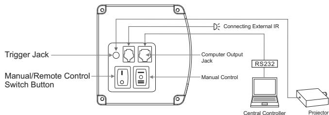
flowchart
graph TD
    A["Trigger Jack"] --> B["Switch Button"]
    C["Manual/Remote Control"] --> B
    D["Computer Output Jack"] --> B
    E["RS232"] --> F["Central Controller"]
    F --> G["Projector"]
    H["Connecting External IR"] --> B
    I["Manual Control"] --> B
Figure 18
How to use manual switch control:
- Switch Manual/Remote Control Button to position "1" (manual stalls).
- Turn the switch to position "=" to lower the screen; it will come down slowly. When it is all the way down, it will stop automatically (Figure 20).
- Turn the switch to position "—" to lower the screen; it will go up into the metal casing. When it is all the way up, it will stop automatically (Figure 21).
- To stop any time while the screen is in motion, turn the switch to 0.
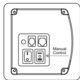
Figure 19
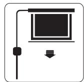
Figure 20
Figure 21