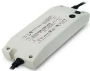
HLN-60H-30A - Okategoriserad Mean Well - Gratis bruksanvisning och manual
Hitta enhetens manual gratis HLN-60H-30A Mean Well i PDF-format.

Användarfrågor om HLN-60H-30A Mean Well
0 fråga om denna apparat. Svara på dem du kan eller ställ din egen.
Ställ en ny fråga om denna apparat
Ladda ner instruktionerna för din Okategoriserad i PDF-format gratis! Hitta din manual HLN-60H-30A - Mean Well och ta tillbaka ditt elektroniska enhet i hand. På denna sida publiceras alla dokument som behövs för att använda din enhet. HLN-60H-30A av märket Mean Well.
BRUKSANVISNING HLN-60H-30A Mean Well
GTIN CODE
MW Search: https://www.meanwell.com/serviceGTIN.aspx
■ Features :
• Universal AC input / Full range (up to 305VAC)
• Built-in active PFC function
- Protections: Short circuit / Over current / Over voltage / Over temperature
• Cooling by free air convection
- OCP point adjustable through output cable or internal potentiometer
• Fully isolated plastic case with IP64 level
- Class 2 power unit
- Three in one dimming function (1\~10Vdc or PWM signal or resistance)
- Suitable for LED lighting, Industrial Lighting and moving sign applications
• Compliance to worldwide safety regulations for lighting
- Suitable for dry / damp locations or outdoor application
• 3 years warranty


SELV
IP64


HLN-60H-15 A: IP64 rated. Output voltage and constant current level can be adjusted through internal potentiometer. B: IP64 rated. Constant current level adjustable through output cable with 1\~10Vdc or 10V PWM signal or resistance.
SPECIFICATION
| MODEL | HLN-60H-15 | HLN-60H-15 | HLN-60H-15 | HLN-60H-30 | HLN-60H-54 | ☐ | ☐ | ☐ | ☐ | |
| OUTPUT | DC VOLTAGE | 15V | 20V | 24V | 30V | 36V | 42V | 48V | 54V | |
| CONSTANT CURRENT REGION Note.4 | 9~15V | 12~20V | 14.4~24V | 18~30V | 21.6~36V | 25.2~42V | 28.8~48V | 32.4~54V | ||
| RATED CURRENT | 4A | 3A | 2.5A | 2A | 1.7A | 1.45A | 1.3A | 1.15A | ||
| RATED POWER | 60W | 60W | 60W | 60W | 61.2W | 60.9W | 62.4W | 62.1W | ||
| RIPPLE & NOISE (max.) Note.2 | 150mVp-p | 150mVp-p | 150mVp-p | 200mVp-p | 200mVp-p | 300mVp-p | 300mVp-p | 300mVp-p | ||
| VOLTAGE ADJ. RANGE Note.6 | 13.5~17V | 17~22V | 22~27V | 27~33V | 33~40V | 40~46V | 44~53V | 49~58V | ||
| CURRENT ADJ. RANGE | Can be adjusted by internal potentiometer A type only | |||||||||
| 2.4~4A | 1.8~3A | 1.5~2.5A | 1.2~2A | 1~1.7A | 0.87~1.45A | 0.78~1.3A | 0.69~1.15A | |||
| VOLTAGE TOLERANCE Note.3 | ±2.0% | ±1.0% | ±1.0% | ±1.0% | ±1.0% | ±1.0% | ±1.0% | ±1.0% | ||
| LINE REGULATION | ±0.5% | ±0.5% | ±0.5% | ±0.5% | ±0.5% | ±0.5% | ±0.5% | ±0.5% | ||
| LOAD REGULATION | ±1.5% | ±1.0% | ±0.5% ±0.5% | ±0.5% | ±0.5% | ±0.5% | ±0.5% | |||
| SETUP, RISE TIME Note.7 | 500ms, 80ms at full load 230VAC / 115VAC | |||||||||
| HOLD UP TIME (Typ.) | 16ms/230VAC 16ms/115VAC at full load | |||||||||
| INPUT | VOLTAGE RANGE Note.5 | 90~305VAC 127~431VDC | ||||||||
| FREQUENCY RANGE | 47~63Hz | |||||||||
| POWER FACTOR (Typ.) | PF>0.98/115VAC, PF>0.95/230VAC, PF>0.92/277VAC at full load (Please refer to "Power Factor Characteristic" curve) | |||||||||
| TOTAL HARMONIC DISTORTION | THD<20% when output loading≥60% at 115VAC/230VAC input and output loading≥75% at 277VAC input | |||||||||
| EFFICIENCY (Typ.) | 87% | 88.5% | 89% | 89.5% | 90% | 90% | 90.5% | 90.5% | ||
| AC CURRENT (Typ.) | 0.64A / 115VAC 0.32A / 230VAC 0.3A / 277VAC | |||||||||
| INRUSH CURRENT(Typ.) | COLD START 55A(width=265 s measured at 50% |peak) at 230VACμ | |||||||||
| MAX. No. of PSUs on 16A CIRCUIT BREAKER | 9 units (circuit breaker of type B) / 16 units (circuit breaker of type C) at 230VAC | |||||||||
| LEAKAGE CURRENT | <0.75mA / 277VAC | |||||||||
| PROTECTION | OVER CURRENT Note.4 | 95~108%Protection type: Constant current limiting, recovers automatically after fault condition is removed | ||||||||
| SHORT CIRCUIT | Hiccup mode, recovers automatically after fault condition is removed | |||||||||
| OVER VOLTAGE | 18~24V | 23~30V | 28~35V | 35~43V | 41~49V | 48~58V | 54~65V | 59~68V | ||
| Protection type: Shut down o/p voltage, re-power on to recover | ||||||||||
| OVER TEMPERATURE | Shut down o/p voltage, re-power on to recover | |||||||||
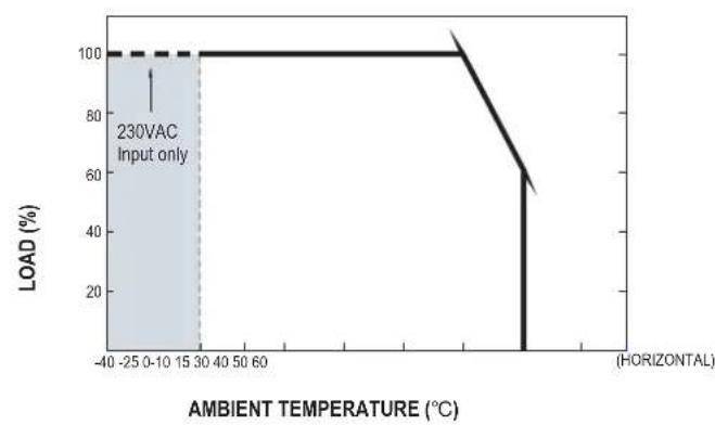
| ENVIRONMENT | WORKING TEMP. | -40~+50°C (Refer to "Derating Curve") | ||||||||
| WORKING HUMIDITY | 20~95% RH non-condensing | |||||||||
| STORAGE TEMP., HUMIDITY | -40~+80°C, 10~95% RH | |||||||||
| TEMP. COEFFICIENT | ±0.03%/°C (0~40°C) | |||||||||
| VIBRATION | 10~500Hz, 2G 12min./1cycle, period for 72min. each along X, Y, Z axes | |||||||||
| SAFETY & EMC | SAFETY STANDARDS | UL8750, CSA C22.2 No. 250.0-08, BS EN/EN 61347-1, BS EN/EN 61347-2-13 independent, IP64, EAC TP TC 004,GB19510.1,GB19510.14 approved; design refer to UL60950-1, BS EN/EN60335-1 | ||||||||
| WITHSTAND VOLTAGE | I/P-O/P:3.75KVAC I/P-FG:2KVAC O/P-FG:0.5KVAC | |||||||||
| ISOLATION RESISTANCE | I/P-O/P, I/P-FG, O/P-FG:100M Ohms / 500VDC / 25°C / 70% RH | |||||||||
| EMC EMISSION | Compliance to BS EN/EN55015, BS EN/EN61000-3-2 Class C (≥60% load): BS EN/EN61000-3-3, GB17743 and GB17625.1, EAC TP TC 020 | |||||||||
| EMC IMMUNITY | Compliance to BS EN/EN61000-4-2,3,4,5,6,8,11; BS EN/EN61547, BS EN/EN55024, light industry level (surge 4KV), EAC TP TC 020 | |||||||||
| MTBF | 3400.0K hrs min. Telcordia SR-332(Bellcore); 347.4K hrs min. MIL-HDBK-217F (25°C) | |||||||||
| DIMENSIONOTHERS | 161*61.5*35mm (L*W*H) | |||||||||
| PACKING | 0.46Kg:32pcs/15.7Kg/1.10CUFT | |||||||||
| NOTE | 1. All parameters NOT specially mentioned are measured at 230VAC input, rated load and 25°C of ambient temperature.2. Ripple & noise are measured at 20MHz of bandwidth by using a 12" twisted pair-wire terminated with a 0.1uf & 47uf parallel capacitor.3. Tolerance : includes set up tolerance, line regulation and load regulation.4. Please refer to "DRIVING METHODS OF LED MODULE".5. Derating may be needed under low input voltages. Please check the static characteristics for more details.6. A type only.7. Length of set up time is measured at cold first start. Turning ON/OFF the power supply may lead to increase of the set up time.8. The power supply is considered as a component that will be operated in combination with final equipment. Since EMC performance will be affected by the complete installation, the final equipment manufacturers must re-qualify EMC Directive on the complete installation again.9. To fulfill requirements of the latest ErP regulation for lighting fixtures, this LED power supply can only be used behind a switch without permanently connected to the mains.10. The ambient temperature derating of 3.5°C/1000m with fanless models and of 5°C/1000m with fan models for operating altitude higher than 2000m(6500ft).11. For any application note and IP water proof function installation caution, please refer our user manual before using.https://www.meanwell.com/Upload/PDF/LED_EN.pdf※ Product Liability Disclaimer : For detailed information, please refer to https://www.meanwell.com/serviceDisclaimer.aspx File Name:HLN-60H-SPEC 2022-04-12 | |||||||||
User's Manual

■ Mechanical Specification
Case No.HLN-60A Unit:mm
A Type:(HLN-60H-_A)
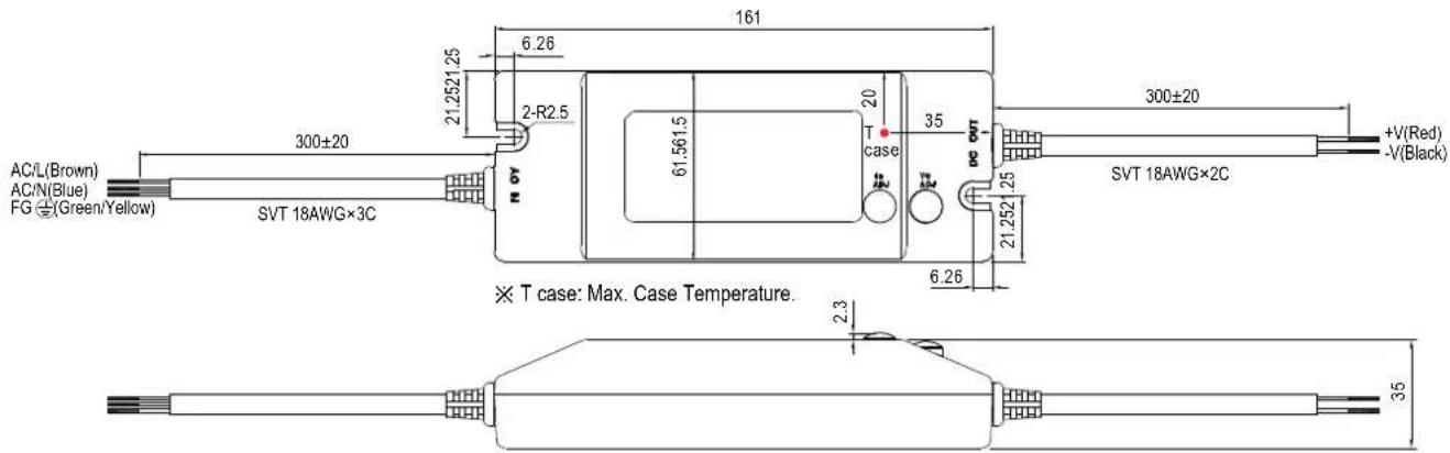
※IP64 rated. Output voltage and constant current level can be adjusted through internal potentiometer. (can access by removing the rubber stopper on the case).
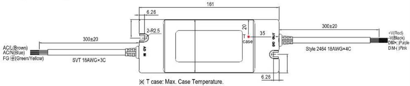
B Type:(HLN-60H-_B)

natural_image
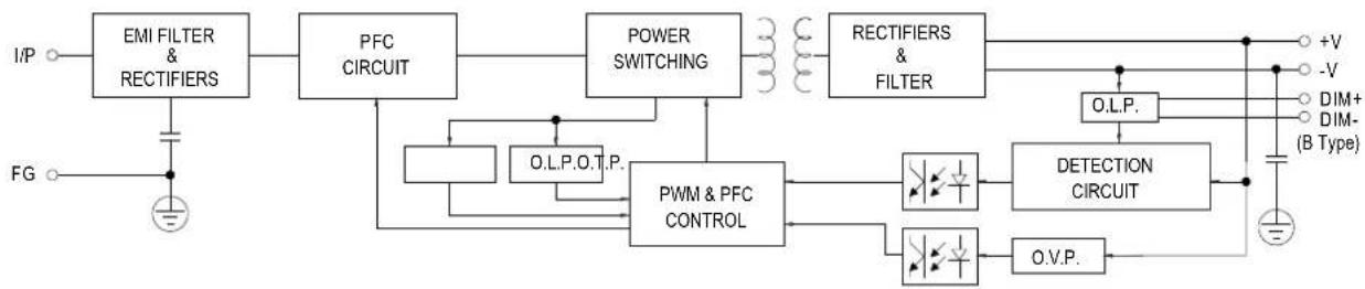
Technical line drawing of a multi-core cable or connector with no text or symbols■ Block Diagram
fosc: 100KHz
flowchart
graph TD
    A["EMI FILTER & RECTIFIERS"] --> B["PFC CIRCUIT"]
    B --> C["POWER SWITCHING"]
    C --> D["RECTIFIERS & FILTER"]
    D --> E["O.L.P."]
    E --> F["DETECTION CIRCUIT"]
    F --> G["+V"]
    F --> H["-V"]
    I["FG"] --> J["Ground"]
    K["+V"] --> L["Ground"]
    M["+V"] --> N["Ground"]
    O["+V"] --> P["Ground"]
    Q["+V"] --> R["Ground"]
    S["+V"] --> T["Ground"]
    U["+V"] --> V["Ground"]
    W["+V"] --> X["Ground"]
    Y["+V"] --> Z["Ground"]
    AA["+V"] --> AB["Ground"]
    AC["+V"] --> AD["Ground"]
    AE["+V"] --> AF["Ground"]
    AG["+V"] --> AH["Ground"]
    AI["+V"] --> AJ["Ground"]
    AK["+V"] --> AL["Ground"]
    AM["+V"] --> AN["Ground"]
    AO["+V"] --> AP["Ground"]
    AQ["+V"] --> AR["Ground"]
    AS["+V"] --> AT["Ground"]
    AU["+V"] --> AV["Ground"]
    AW["+V"] --> AX["Ground"]
    AY["+V"] --> AZ["Ground"]
    BA["+V"] --> BB["Ground"]
    BC["+V"] --> BD["Ground"]
    BE["+V"] --> BF["Ground"]
    BG["+V"] --> BH["Ground"]
    BI["+V"] --> BJ["Ground"]
    BK["+V"] --> BL["Ground"]
    BM["+V"] --> BN["Ground"]
    BO["+V"] --> BP["Ground"]
    BQ["O.L.P.O.T.P."] --> BR["PWM & PFC CONTROL"]
    BR --> BS["PWM & PFC CONTROL"]
    BS --> BT["PWM & PFC CONTROL"]
    BT --> BU["PWM & PFC CONTROL"]
    BU --> BV["PWM & PFC CONTROL"]
    BW["PWM & PFC CONTROL"] --> BX["PWM & PFC CONTROL"]
    BX --> BY["PWM & PFC CONTROL"]
    BY --> BZ["PWM & PFC CONTROL"]
    BX --> BYP["PWM & PFC CONTROL"]
    BYP --> BZ
    BX --> BYR["PWM & PFC CONTROL"]
    BYR --> BZ
    BX --> BYS["PWM & PFC CONTROL"]
    BYS --> BYR
    BX --> BYP
    BX --> BYS
    BX --> BYR
■ Derating Curve Static Characteristics
line
| AMBIENT TEMPERATURE (°C) | LOAD (%) | | ------------------------ | -------- | | -25 | 100 | | 0 | 100 | | 15 | 100 | | 30 | 100 | | 40 | 100 | | 50 | 100 | | 60 | 100 | | >60 | 60 |
line
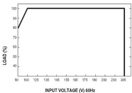
| INPUT VOLTAGE (V) 60Hz | LOAD (%) | | ---------------------- | -------- | | 90 | 80 | | 100 | 100 | | 305 | 100 |■ Power Factor Characteristic
line
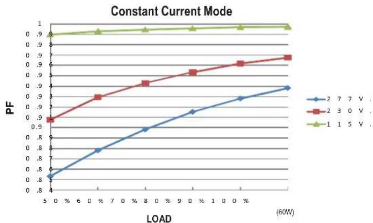
| LOAD (60W) | 2 V | 3 V | 5 V | | ---------- | ------ | ------ | ------ | | 5 | 0.8 | 0.9 | 1.0 | | 0 | 0.8 | 0.9 | 1.0 | | 7 | 0.8 | 0.9 | 1.0 | | 8 | 0.8 | 0.9 | 1.0 | | 0 | 0.8 | 0.9 | 1.0 | | 9 | 0.8 | 0.9 | 1.0 | | 0 | 0.8 | 0.9 | 1.0 | | 1 | 0.8 | 0.9 | 1.0 | | 0 | 0.8 | 0.9 | 1.0 | | 1 | 0.8 | 0.9 | 1.0 | | 0 | 0.8 | 0.9 | 1.0 | | 1 | 0.8 ] | 0.9 ] | 1.0 ] | | 0 | 0.8 ] | 0.9 ] | 1.0 ] | | 1 | 0.8 ] | 0.9 ] | 1.0 ] | | 0 | 0.8 ] | 0.9 ] | 1.0 ] | | 1 | 0.8 ] | 0.9 ] | 1.0 ] | | 0 | 0.8 ] | 0.9 ] | 0.99 | | 1 | 0.8 ] | 0.9 ] | 0.99 | | 0 | 0.8 ] | 0.9 ] | 0.99 | | 1 | 0.8 ] | 0.9 ] | 0.99 | | 0 | 0.8 ] | 0.9 ] | 0.99 | | 1 | 0.8 ] | 0.9 ] | 1.0 | | 0 | 0.8 ] | 0.9 ] | 1.0 | | 1 | 0.8 ] | 0.9 ] | 1.0 | | 0 | 0.8 ] | 0.9 ] | 1.0 | | 1 | 0.8 ] | 0.9 ] | 1.0 | | 0 | 0.8 ] | 0.9 ] | 1.0 | | 1 | 0.8 ] | 0.9 ] | 1.0 | | 0 | 0.8 ] | 0.9 ] | 1.0 | | 1 | 0.8 ] | 0.9 ] | 1.0 | | 0 | 0.8 ] | 0.9 ] | 1.0 | | 1 | 0.8 ] | 0.9 ] | 1.0■ EFFICIENCY vs LOAD (48V Model)
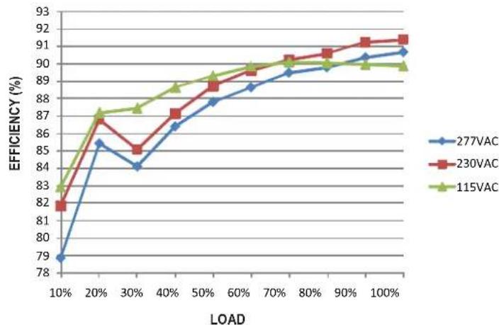
HLN-60H series possess superior working efficiency that up to 90.5% can be reached in field applications.
line
| LOAD | 277VAC | 230VAC | 115VAC | | ---- | ------ | ------ | ------ | | 10% | 78.5 | 81.8 | 83.0 | | 20% | 85.5 | 86.8 | 87.2 | | 30% | 84.0 | 85.0 | 87.5 | | 40% | 86.5 | 87.2 | 88.5 | | 50% | 87.8 | 88.5 | 89.2 | | 60% | 88.5 | 89.0 | 89.5 | | 70% | 89.0 | 90.0 | 90.2 | | 80% | 89.5 | 90.5 | 90.3 | | 90% | 90.0 | 91.0 | 90.0 | | 100% | 90.5 | 91.2 | 89.8 |■ DRIVING METHODS OF LED MODULE
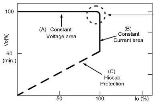
There are two major kinds of LED drive method "direct drive" and "with LED driver".
A typical LED power supply may either work in "constant voltage mode (CV) or constant current mode (CC)" to drive the LEDs.
Mean Well's LED power supply with CV+ CC characteristic can be operated at both CV mode (with LED driver, at area (A) and CC mode (direct drive, at area (B)).
line
| Io (%) | Vo (min.) | | ------ | --------- | | 0 | 100 | | 50 | 100 | | 100 | 60 | | 100 | 100 |In the constant current region, the highest voltage at the output of the driver depends on the configuration of the end systems.
Should there be any compatibility issues, please contact MEAN WELL.
Typical LED power supply I-V curve
■ DIMMING OPERATION(for B-type only)
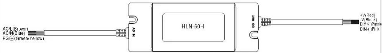
Built-in 3 in 1 dimming function, IP64 rated. Output constant current level can be adjusted through output cable by connecting a resistance or 1 \~ 10Vdc or 10V PWM signal between DIM+ and DIM-.
※Please DO NOT connect "DIM-" to "-V".
※Reference resistance value for output current adjustment (Typical)
| Resistance value | Single driver | 10KΩ | 20KΩ | 30KΩ | 40KΩ | 50KΩ | 60KΩ | 70KΩ | 80KΩ | 90KΩ | 100KΩ | OPEN |
| Multiple drivers(N=driver quantity for synchronized dimming operation) | 10KΩ/N | 20KΩ/N | 30KΩ/N | 40KΩ/N | 50KΩ/N | 60KΩ/N | 70KΩ/N | 80KΩ/N | 90KΩ/N | 100KΩ/N | ---- | |
| Percentage of rated current | 10% | 20% | 30% | 40% | 50% | 60% | 70% | 80% | 90% | 100% | 95%~108% | |
※1 \~ 10V dimming function for output current adjustment (Typical)
2V
| 5V D morning value | 1V 4V | 7V | OPEN | ||||||||
| Percentage of rated current | 10% | 20% | 30% | 40% | 50% | 60% | 70% | 80% | 90% | 100% | 95%~108% |
※10V PWM signal for output current adjustment (Typical): Frequency range: 100Hz \~ 3KHz
| Duty value | 10% | 20% | 30% | 40% | 50% | 60% | 70% | 80% | 90% | 100% | OPEN |
| Percentage of rated current | 10% | 20% | 30% | 40% | 50% | 60% | 70% | 80% | 90% | 100% | 95%~108% |
※Using the built-in dimming function on B-type model can't turn the lighting fixture totally dark. Please refer to the connection method below to achieve 0% brightness of the lighting fixture connecting to the LED power supply unit.
※Direct connecting to LEDs is suggested, but is not suitable for using additional drivers.
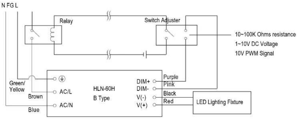
Dimming connection diagram for turning the lighting fixture ON/OFF :
flowchart
graph TD
    A["N FG L"] --> B["Relay"]
    B --> C["Switch Adjuster"]
    C --> D["10~100K Ohms resistance"]
    C --> E["1~10V DC Voltage"]
    C --> F["10V PWM Signal"]
    G["Green/Yellow"] --> H["Brown"]
    H --> I["HLN-60H B Type"]
    I --> J["Blue"]
    I --> K["AC/N"]
    I --> L["AC/L"]
    I --> M["DIM+"]
    I --> N["DIM-"]
    I --> O["V(-)"]
    I --> P["V(+)"]
    I --> Q["Purple"]
    I --> R["Pink"]
    I --> S["Black"]
    I --> T["Red"]
    I --> U["LED Lighting Fixture"]
Using a switch and relay can turn ON/OFF the lighting fixture.
-
Output constant current level can be adjusted through output cable by connecting a resistance or 1\~10Vdc or 10V PWM signal between DIM+ and DIM-.
-
The LED lighting fixture can be turned ON/OFF by the switch.