DADP-DGC-18-KF - Okategoriserad Festo - Gratis bruksanvisning och manual
Hitta enhetens manual gratis DADP-DGC-18-KF Festo i PDF-format.

Användarfrågor om DADP-DGC-18-KF Festo
0 fråga om denna apparat. Svara på dem du kan eller ställ din egen.
Ställ en ny fråga om denna apparat
Ladda ner instruktionerna för din Okategoriserad i PDF-format gratis! Hitta din manual DADP-DGC-18-KF - Festo och ta tillbaka ditt elektroniska enhet i hand. På denna sida publiceras alla dokument som behövs för att använda din enhet. DADP-DGC-18-KF av märket Festo.
BRUKSANVISNING DADP-DGC-18-KF Festo
DADP-DGC
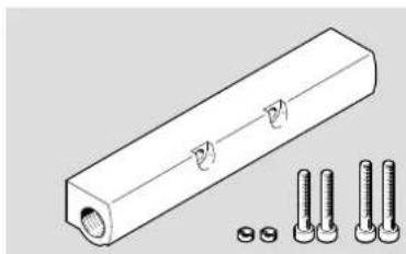
Shock absorber retainer
natural_image
Technical illustration of a rectangular mechanical part with three bolts and a screw base (no text or symbols)FESTO
Festo SE & Co. KG
Ruiter Straße 82
73734 Esslingen
Germany
+49 711 347-0
www.festo.com
Assembly instructions
8174040
2022-11c
[8174042]

8174040
Translation of the original instructions
© 2023 all rights reserved to Festo SE & Co. KG
1 Applicable documents
□1
All available documents for the product → www.festo.com/sp.
| Document Product Table of contents | ||
| Operating instruction Linear drive | DGC(I) - | |
| Assembly instructions Stop KYC - | ||
| Operating instruction Intermediate | e-position module DADM-DGC-25...40 | - |
Tab. 1: Applicable documents
2 Safety
2.1 Safety instructions
- Only use the product in its original condition without unauthorised modifications.
-Observe the tightening torques. Unless otherwise specified, the tolerance is ± 20%.
2.2 Intended use
The shock absorber retainer fastens shock absorbers YSR(W)-DGC to the slide of linear drives DGC-...-GF/-KF/-FA or DGCI. Use the shock absorber retainer only in combination with a counter part for the cushioning:
-Stop KYC
-Intermediate-position module DADM-DGC
3 Additional information
-Contact the regional Festo contact if you have technical problems
→ www.festo.com.
-Accessories → www.festo.com/catalogue.
4 Product Range Overview
4.1 Scope of delivery
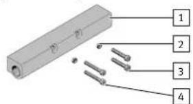
text_image
Diagram of a rectangular electronic component with four labeled parts, likely illustrating a pin or connector assembly.1 Shock absorber retainer (1x)
2 Centring sleeve (2x)
3 Screw (2x), only with DADP-DGC- ... -KF
4 Screw (2x)
Fig.1
4.2 Not in scope of delivery
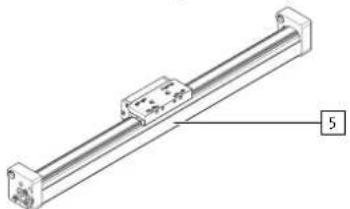
natural_image
Technical line drawing of a linear mechanical component with a labeled dimension (no text or symbols present)5 Linear drive (1x)
DGC-...-GF
DGC-...-KF
DGC-...-FA.
DGCI
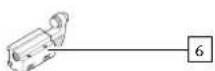
6 Stop (1x/2x) KYC
Fig.2
Fig.3
Fig.4
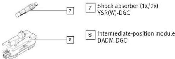
text_image
Shock absorber (1x/2x) YSR(W)-DGC Intermediate-position module DADM-DGCFig.5
5 Assembly
5.1 Preparation for DADP-DGC-18 ... -40
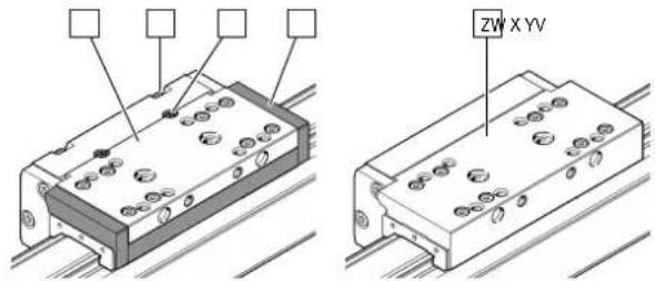
text_image
ZW X YVFig.6
- Check the slide of the linear drive 5.
Steel slide:
-Multi-piece slide [V]
- Screws [W], spring pins [X] and plastic cover [Y]
Aluminium slide:
- One-piece slide [Z]
5.2 Mounting shock absorber retainer
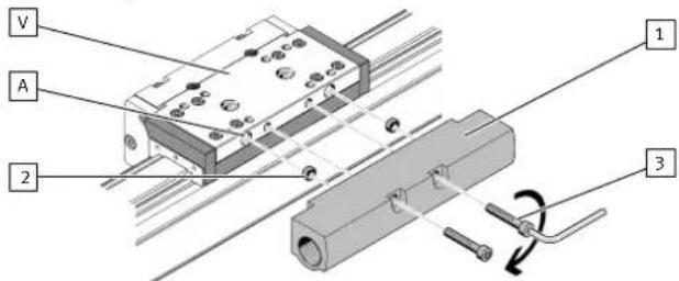
text_image
V A 2 1 3Fig. 7: Mounting on steel slide
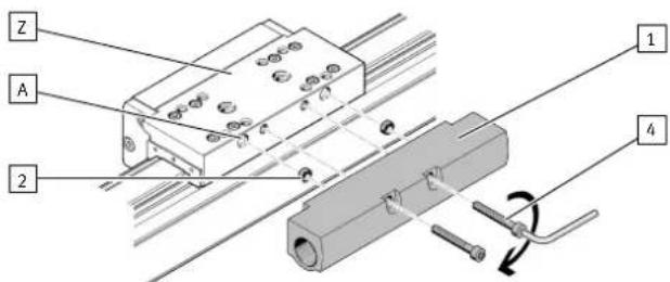
text_image
Z A 2 1 4Fig. 8: Mounting on aluminium slide
1. Place the centring sleeves 2 in the seats [A].
2. Place the shock absorber holder 1 on the centring sleeves 2.
3. Select the appropriate screws 3/4:
- shorter screws 3 for multi-piece steel slide [V].
- longer screws 4 for one-piece aluminium slide [Z].
Two screws are left over with DADP-DGC- ... -KF.
- Tighten the screws 3/4. Observe the tightening torque.
| DADP-DGC | -18-GF | -25-GF | -32-GF | -18-KF | -25-KF | -32-KF |
| Screw 3 – | M5 x 30 | |||||
| Screw 4 M5 x 30 | M5 x 35 | |||||
| [Nm] | 4 | 6 | ||||
| DADP-DGC | -40-GF | -40-KF | -50 | -63 |
| Screw 3- | M6 x 35 | - | ||
| Screw 4 M6 x 35 | M6 x 45 | M8 x 45 | ||
| [Nm] | 8 | 10 | 25 | |
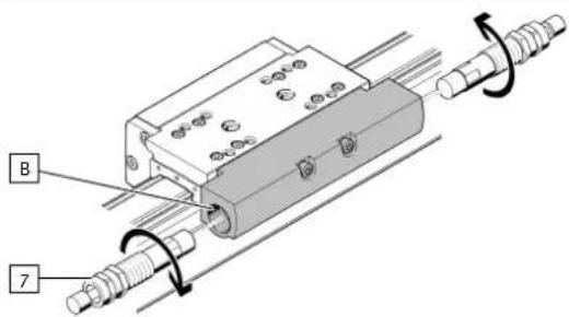
5.3 Mounting shock absorber
i
If available, shock absorbers from the end cap of the linear drive 5 can be used.
text_image
B 7Fig.9
- Depending on requirements screw one or two shock absorbers 7 with stop sleeve and lock nut completely into the shock absorber retainer 1. Observe the tightening torque of the lock nut.
| YSR(W)-DGC | -18-GF -25 | GF -32-GF | -18-KF -25 | -KF -32-KF | ||
| [Nm] | 3 5 8 5 20 20 | |||||
| YSR(W)-DGC | -40-GF -40/50-B -63 | |||||
| [Nm] | 20 35 30 | |||||
5.4
Mounting stop elements
- Mount one or two stops 6 depending on requirements → 1 Applicable documents.
- Mount intermediate-position modules 8 depending on requirements → 1 Applicable documents.