301121 - TV-antenn Wilson - Gratis bruksanvisning och manual
Hitta enhetens manual gratis 301121 Wilson i PDF-format.

Användarfrågor om 301121 Wilson
0 fråga om denna apparat. Svara på dem du kan eller ställ din egen.
Ställ en ny fråga om denna apparat
Ladda ner instruktionerna för din TV-antenn i PDF-format gratis! Hitta din manual 301121 - Wilson och ta tillbaka ditt elektroniska enhet i hand. På denna sida publiceras alla dokument som behövs för att använda din enhet. 301121 av märket Wilson.
BRUKSANVISNING 301121 Wilson
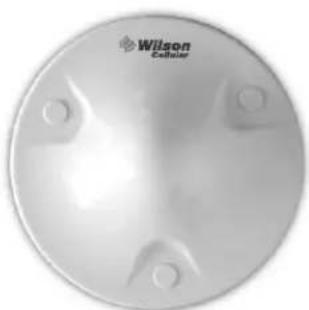
Dual-Band Dome Antenna
Part# 301121
This package contains: Dual-Band Dome Antenna, antenna installation kit, and a template with instructions for installing on the ceiling. See reverse side for installation template.
TECHNICAL SUPPORT
Call Toll-Free 866-294-1660
E-mail tech@wilsonelectronics.com
Visit www.wilsonelectronics.com
Specifications
| Part Number 301121 | |
| Frequency Range 800~910 MHz / 1800~1990 MHz | |
| Gain 2.5 dBi | |
| Polarization Vertical | |
| Max Power 50 watts | |
| Impedance 50 ohms | |
| Connector N-Female | |
| Diameter 8 (inch) / 20.32 (cm) | |
natural_image
Circular metallic object with four mounting holes and a logo reading 'Wilson Celliner' (no additional text or symbols)
Wilson®
Electronics, Inc.
3301 East Deseret Drive, St. George, Utah 84790
For additional technical support visit
www.wilsonelectronics.com
Phone: 866-294-1660
Part # 301121
Dual-Band Dome Antenna
Installation Instructions and Template
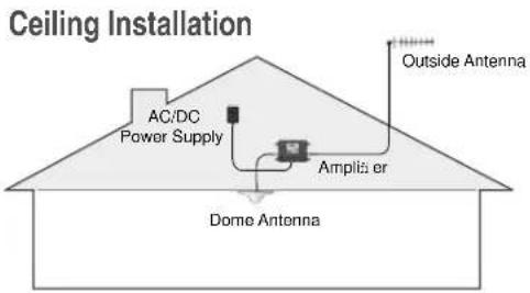
The Dual-Band Dome Antenna is designed for horizontal installation on a ceiling. It is not designed for a vertical or slanted surface, such as a wall.
screw location
screw location

Select a location on the ceiling that you can access from above to run the antenna cable. Verify that your chosen location allows for the necessary separation between the dome antenna and the outside antenna (see amplifier Installation Instructions for antenna separation requirements).
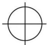
Tape this template in the selected antenna location. NOTE: ensure that the cable connector location (marked by ⊕) is NOT below a ceiling stud. Drill a 5/8-inch hole in the template at the spot marked ⊕. Feed the cable from above through the hole.
Included are two sets of mounting hardware: A) 3 bolts with nuts and washers, B) 3 self-starting screws, and 3 mounting plugs.
A) If using the bolts, drill a 1/8" hole through each of the small circles marked "screw location." Remove template from the ceiling, attach the dome antenna to the amplifier cable, insert the bolts through the drilled holes, and tighten against the ceiling with the enclosed nuts and washers. Snap the plugs into place on the mounting holes.
B) If using the self-starting screws, mark the screw locations, remove the template, and attach the amplifier cable to the dome antenna. Place the antenna flush against the ceiling and screw in the self-starting screws until snug. Be careful not to over-tighten. Snap the plugs into place on the mounting holes.
If you have any questions about the installation procedure, please contact our Technical Support Department toll free at 866-294-1660 or email tech@wilsonelectronics.com.