RAS-10LH1 - клима уређај HITACHI - Besplatni korisnički priručnik
Pronađite besplatno priručnik za uređaj RAS-10LH1 HITACHI u PDF formatu.

Pitanja korisnika o RAS-10LH1 HITACHI
0 питање о овом уређају. Одговорите на оне које знате или поставите своје.
Постави ново питање о овом уређају
Preuzmite uputstvo za vaš клима уређај u PDF formatu besplatno! Pronađite svoj priručnik RAS-10LH1 - HITACHI i uzmite svoju elektronsku napravu nazad u ruke. Na ovoj stranici su objavljeni svi dokumenti potrebni za korišćenje vaše naprave. RAS-10LH1 marke HITACHI.
KORISNIČKI PRIRUČNIK RAS-10LH1 HITACHI
FOR SERVICE PERSONNEL ONLY
HITACHI
Inspire the Next
SPLIT UNIT AIR CONDITIONER INSTALLATION MANUAL
Indoor Unit
RAS-08LH1/RAS-08LH1(B)
RAS-10LH1/RAS-10LH1(B)
RAS-14LH1/RAS-14LH1(B)
RAS-14LHT/RAS-14LHT(B)
Outdoor Unit
RAC-08LH1
RAC-10LHT RAC-14LH1
RAC-14LH
- Carefully read through the procedures of proper
installation before starting installation work. - The sales agent should inform customers regarding the correct operation of installation.
TOOLS NEEDED FOR INSTALLATION WORK
- ⊕ ⊖ Screwdriver • Measuring Tape • Knife
- Saw • e 65mm Power Drill • Hexagonal Wrench
Key ( 4mm) • Wrench (14, 17, 22mm) • Gas Lockpress Detector - Dine Cutter - Putters - Vinc
Leakage Detector • Pipe Cutter • Putty • V Tape • Pliers • Flare Tool • Vacuum pump - File
- Manifold Valve
- Charge Hose
- Reamer
THE CHOICE OF MOUNTING SITE (Please note the following matters and obtain permission from customer before installation).
WARNING
- The unit should be mounted at stable, non-vibratory location which can provide full support to the unit.
CAUTION
- No nearby heat source and no obstruction near the air outlet is slowed.
- The clearance distances from tap, right and left are specified in figure below.
- The location must be convenient for water drainage and pipe connection with the Clusters unit.
- To avoid interference from noise please place the unit and its remote
controller at least 1m from the radio, television and inverter type 3 power ball lamp. - To avoid any error in signal transmission from the remote controller.
please put the controller far away from high-frequency machines and high-power wireless systems.
● The installation height of indoor unit must be 2.3m or more.
OUTDOOR UNIT
WARNING
- The Outdoor unit must be mounted at a location which can support heavy weight. Otherwise, noise and vibration will increase.
CAUTION
Do not expose the unit under direct sunshine or rain. Besides, ventilation must be good and clean at obstruction.
- The air down out of the unit should not point directly to animals or plants.
- The cleasuries of the unit from top, left, right and front are specified in 6 curn below. At least 3 of the above sides must be open as
- Be sure that the hot air blown out of the unit and nose do not disturb the
5. Neighbourhood.
• Do not install at a location where there is Il ammable gas, steam, oil and
stroke.
- The location must be convenient for water drainage.
- Place the Outdoor unit and its connecting area at least 1 m away from the
■ Focal and wireless drive on the following line in radio: In ways, I am the antenna or signal line of television, radio or telephone. This is to avoid noise.
- Do not install outdoor unit fading strong wind clefting. It may damage the
fan motor
SAFETY PRECAUTION
- Read the safety precautions carefully before operating the unit.
- The contents of this section are vital to ensure safety. Please pay special attention to the following sign.
WARNING ..... Incorrect methods of installation may cause death or serious injury.
⚠️ CAUTION ...... Improper installation may result in serious consequence.
Be sure that the unit operates in proper condition after installation. Explain to customer the proper way of operating the unit as described in the user's guide.
WARNING
- Please request your sales agent or qualified technician to install your unit. Water leakage, short circuit or fire may occur if you do the installation work yourself.
- Please observe the instructions stated in the installation manual during the process of installation. Improper installation may cause water leakage, electric shock and fire.
- Make sure that the units are mounted at locations which are able to provide full support to the weight of the units. If not, the units may collapse and impose danger.
- Observe the rules and regulations of the electrical installation and the methods described in the installation manual when dealing with the electrical work. Use power cables approved by the authorities of your country.
- Be sure to use the specified wire for connecting the indoor and outdoor units. Please ensure that the connections are light after the conductors of the wire are inserted into the terminals. Improper insertion and loose contact may cause over-heating and fire.
- Please use the specified components for installation work. Otherwise, the units may collapse or water leakage, electric shock and fire may occur.
- Be sure to use the specified piping set for R410A. Otherwise, this may result in broken copper pipes or faults.
- When installing or removing an air conditioner, do not allow air or moisture to remain in the refrigeration cycle. Otherwise, pressure in the refrigeration cycle may become abnormally high so that a rupture may be caused.
- Be sure to ventilate fully if a refrigerant gas leak while at work. If the refrigerant gas comes into contact with fire, a poisonous gas may occur.
- After completion of installation work, check to make sure that there is no refrigeration gas leakage. If the refrigerant gas leaks into the room, coming into contact with fire in the fan-driven heater, space heater, etc., a poisonous gas may occur.
- Unauthorized modifications to the air conditioner may be dangerous. If a breakdown occurs please call a qualified air conditioner technician or electrician. Improper repairs may result in water leakage, electric shock and fire, etc.
CAUTION
- A circuit breaker or fuse must be installed. Without a circuit breaker or fuse the danger of electric shock exists.
A main switch with a contact gap of more than 3mm has to be installed in the power supply line to the outdoor unit. - Do not install the unit near a location where there is flammable gas. The outdoor unit may
catch fire if flammable gas leaks around it. - Please ensure smooth flow of water when installing the drain hose.
- Piping shall be suitable supported with a maximum spacing of 1m between the supports.

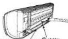
Names of Indoor Components
| Qty | ||
| 1 | Hanger | 1 |
| 2 | Screw for Hanger(4.1x 32) | 6 |
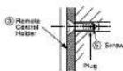
| 3 | Holder for Remote Controller | 1 |
| 4 | AAA Size Battery | 2 |
| 5 | Screw for holder of Remote Controller(3.1x 16) | 2 |
| 6 | Remote Controller | 1 |
| 7 | Purifying Filter | 2 |
| 8 | Holder | 1 |

There are 4 directions allowed, namely, horizontally perpendicular to the unit, vertically down from right, horizontally out from right and horizontally out to left. Don't form the piping downward at the left of the unit.
Names of Outdoor Components
| QtyNo. | ||
| ® | Drain Pipe | 1 |
Item

text_image
above 200mm above 50mm when installed on the ceiling of territory above 100mm above 200mm e give clearance as wide as possible above 700mmallation of Indoor and Outdoor Unit.
CAUTION
• The installation height of indoor
unit must be 2.3m or more.

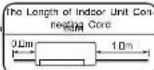
● The difference in height between the indoor and outdoor unit should be kept max 10m.
- The connecting pipe, no matter big or small, should all be insulated with insulation pipe and then wrapped with vinyl tape. (The insulator will deteriorate if it is not wrapped with tape).
The connection of insulated drain hose. Please use insulated drain hose for the indoor piping (commercial product).
1 Installation of Hanger, Wall Penetration and Installation of Protection Pipe
CAUTION
- The draining of the water container inside the indoor unit can be done from the left. Therefore the hanger must be fixed horizontally or slightly tilted towards the side of drain hose. Otherwise, condensed water may overflow the water container.
Direct Mounting On The Wall
Please use hidden beams in the wall to hold the hanger.
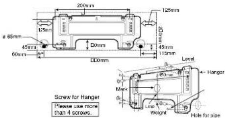
text_image
200mm 125mm 125mm a 65mm 45mm 60mm D0mm 45mm 115mm L00mm Level Hanger Screw for Hanger Please use more than 4 screws. Mark Line Weight Hole for pipeProcedures of Installation and Precautions
• Procedures to fix the hanger.
Drill holes on wall. 2. Push plug into the holes. (As shown below) (As shown below)
- Fix the hanger on wall with 4.1 x 32 screw (As shown in figure below


4.1 x 32 Screw
- Procedures to fix the holder of remote control. 1. Drill holes on wall. (As shown below) 2. Push plug into the holes. (As shown below)

Wall Penetration and Installation of Protection Pipe
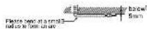
- Drill a c 65mm hole on wall which is slightly tilted towards the outdoor side. Drill the wall at a small angle.
- Cut the protection pipe according to the wall thickness.
● Empty gap in the sleeve of protection pipe should be completely sealed with putty to avoid dripping of rain water into the room.

WARNING
Be sure that the wire is not in contact with any metal in the wall. Please use the protection pipe as wine passing through the hollow part of the wall so as to prevent the possibility of damaged by mouse. Unless it seals completely, any air with high humidity flows from outdoor and any dew may drop.
Installation of the Indoor Unit
VERTICALLY DOWNWARD PIPING
Preparation
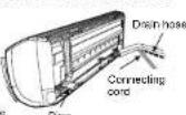
- Connect connecting cord.
- Pull out the pipe, connecting cord and drain hose.
Connecting roads, pipe and drain face must be laid together with City face
Installation
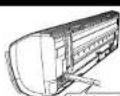
- The upper part of the indoor unit is hanged on the hanger.
- The projection at the lower part of the Indoor unit is hooked onto the hanger.


⚠ CAUTION Please pull the lower part of the Indoor unit outwards to check if the unit is hooked onto the hanger. Improper installation may cause vibration and noise.
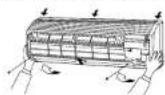
HOW TO REMOVE INDOOR UNIT
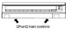
- Push up the (PUSH) sections at the bottom of the indoor unit and pull the bottom plate towards you. Then the claws are released from the stationary plate.
(The (PUSH) sections are indicated by 2 arrows in the right figure)
(The (PUSH) sections are indicated by 2 arrows in the right figure)
(1) 本说明仅供参考。
(No text)
HORIZONTAL PIPING
Preparation
Change of Drain Hose and Installation Procedures.
- Exchange the location of drain hose and drain cap during horizontal piping as shown in figure below. Be sure to plug in the drain hose until the insulating material folds upon itself
Please use pliers to pull out the drain cap. (This is an easier way to remove the drain cap)


CAUTION Condensed water may leak out if not inserted properly.
HORIZONTAL & DOWNWARD PIPING - MAKING OPENINGS
- During horizontal or downward piping, use a knife to cut openings as shown in figure. Then smoothen the edges of openings with a file.

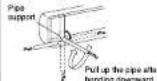
INSTALLATION OF REFRIGERATING PIPES AFTER CONNECTION
- The refrigerating pipes should be adjusted to fit into the
hole on the wall and then ready for further connection. The terminals of 2 connected pipes must be covered - The terminals of a connected pipe must be covered with insulator used for terminal connection. Then the
pipes are wrapped with insulation pipe. - Connect the connecting cord after removing electrical circuit (Refrats Connection of Power, 600V)
cover. (Refer to "CONNECTION OF POWER CORD") After adjustment, fill live connecting card and pipe - After adjustment, if the connecting color and ppt into the space available under the indoor unit. Use holder to hold them tight.
Insulation plan must be w/v vind 200 at every 125mm
- Holder can be attached at the either of 2 places. Please select the easier position.
CAUTION
- The rubber strap used for fixing the insulator should not be tied with great force. Otherwise, this will damage heat insulation and causes water condensation.

THE CONNECTION OF REFRIGERATING PIPE DURING THE INSTALLATION OF INDOOR UNIT
Preparation To Install Refrigerating Pipes
- The refrigerating pipes and connecting cord transform and are attached.
- The end of the refrigerating pipes are at locations marked with "▽" symbol.

Installation
Hang the Indoor unit onto the hanger. Use the temporary stand at the back of the Indoor unit to push its lower part 15cm forwards.
- Place the drain hose through the hole on the wall.
- Wrap the refrigerating pipes with insulation pipe after connecting refrigerating pipe.
- Connect the connecting cord after removing electrical cover. (Refer to "Connection of Power Cord")
● After adjustment, the connecting cord and refrigerating pipes
are placed into the space available under the Indoor u
- The projection of Indoor unit must hook to the hanger.

Refrigerating pipe

3 Installation of Drain Hose

CAUTION Be sure that the drain hose is not loosely connected or bend.
CAUTION You are free to choose the side (left or right) for the installation of drain hose. Please ensure the smooth flow of condensed water of the Indoor unit during installation. (Carelessness may result in water leakage.)
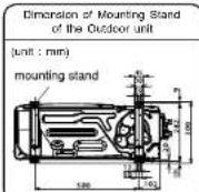
- Mount the outdoor unit on stable ground to prevent vibration and increase of noise level.
- Decide the location for piping after sorting out the different types of pipe available. Please face this side (suction side) of the unit to the wall.
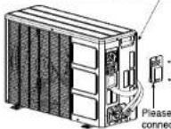
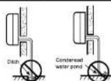
CONDENSED WATER DISPOSAL OF OUTDOOR UNIT
- There are holes on the base of Outdoor unit for condensed water to exhaust.
- In order to flow condensed water to the drain, the unit must be installed as shown. The unit must be 100mm and above the ground. Join the drain pipe to one hole. BRACKET

Ensure that the front side of unit is higher than the back by 10mm
- At first insert one portion of the hook to the base (Portion A), then pull the drain pipe in the direction shown by the arrow while inserting the hook into the base. After installation, check whether the drain pipe cling to the base firmly.

When Using and Installing in Cold Areas
When the air conditioner is used in low temperature and in snowy conditions, water from the heat exchanger may freeze on the base surface to cause poor drainage. When using the air conditioner in such areas, do not install the bushings. Keep a minimum of 250mm between the drain hole and the ground. When using the drain pipe, consult your sales agent.
For more details, refer to the installation
Manual for Cold Areas.
INSTALLATION OF REFRIGERATING PIPES AND AIR REMOVAL
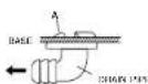
Preparation of Pipe
- Use a pipe cutter to cut the copper pipe.
CAUTION
- Jagged edge will cause leakage.
- Point the side to be trimmed downwards during trimming to prevent copper chips from entering the pipe.
- Before ll arising, please put on the ll are


- Please use exclusive tool
| Outer Diameter (mm) | A (mm) | |
| For R410A tool | For R22 tool | |
| 6.35 | 0.0 ~ 0.5mm | 1.0mm |
| 9.52 | 0.0 ~ 0.5mm | 1.0mm |
| 12.70 | 0.0 ~ 0.5mm | 1.0mm |
2 Pipe Connection
CAUTION
In case of removing fl are nut of an indoor unit, fl rst remove a nut of small diameter side, or a seal cap of big diameter side will fl y out. Prevent water from entering into the piping when working.
- Please be careful when bending the copper pipe.
- Screw in manually while adjusting the center. After that, use of torque wrench to tighten the connection.
| Outer do of pipe | Torque Nm (g·L·cm) | ||
| Small dia. side | 6.35 (1/4") | 13.7 - 18.6 (190 - 190y) | |
| Large dia. side | 9.52 (2/8") | 34.3 - 44.1 (350 - 450y) | |
| 12.7 (1/2") | 44.1 - 53.9 (150 - 550y) | ||
| Valve head cap | Small dia. side | 6.35 (1/4") | 19.6 - 24.5 (200 - 250y) |
| Large dia. side | 9.52 (2/8") | 19.6 - 24.5 (200 - 250y) | |
| 12.7 (1/2") | 29.4 - 34.3 (300 - 350y) | ||
| Valve core cap | 12.5 - 15.7 (125 - 150y) | ||
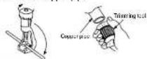
3 Removal Of Air From The Pipe And Gas Leakage Inspection
Procedures of using Vacuum Pump for Air Removal
1
As shown in right figure, remove the cap of valve core. Then, connect the charge hose. Remove the cap of valve head. Connect the vacuum pump adapter to the vacuum pump and connect the charge hose to the adapter.
-
2
Fully tighten the "Hi" shuttle of the manifold valve and completely unscrew the "Lo" shuttle. Run the vacuum pump for about 10–15 minutes, then completely tighten the "Lo" shuttle and switch off the vacuum pump.
3
Completely unscrew the spindle of the service valve (at 2 places) in anti-clockwise direction to allow the flow of coolant (using Hexagonal Wrench key).
4
Remove the charge hose and tighten the cap of valve head. Check the cap's periphery if there is any gas leakage. The task is then completed.

text_image
When the motor reaches - 101KPa (-750mmHg) during pumping, fully tighten the shuttle. Closed Closed water Close Volume Volume Vacuum pump Vacuum pump adapter Vacuum pump When pumping stars, slightly loosen the fuse out to clean air inside in. Then tighten the fuse out.
Gas Leakage Inspection
Please use gas leakage detector to check if leakage occurs at the connection of Flare nut as shown on the right.
If gas leakage occurs, further tighten the connection to step leakage.

WARNING
- THIS APPLIANCE MUST BE EARTHED.
Procedures of Wiring
In case that power is supplied from Indoor Unit
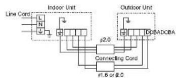
flowchart
graph TD
    A["Line Cord L"] --> B["Indoor Unit"]
    C["N"] --> B
    B --> D["Connecting Cord"]
    D --> E["Outdoor Unit"]
    F["DCB"] --> D
    G["ADCBA"] --> D
    H["∅2.0"] --> D
    I["∅1.6 or ∅2.0"] --> D

text_image
Power line Control line 30mm 30mm 10mm 10mm 10mm 70mm GNN + YEL Indoor Unit Strip wire Outdoor Unit 25mm 25mm 10mm 10mm GNN + YEL 35mmWARNING
- The naked part of the wire core should be 10 mm and fix it to the terminal tightly. Then try to pull the individual wire to check if the contact is tight. Improper insertion may burn the terminal.
- Be sure to use only power cables approved from the authorities in your country. For example in Germany: Cable type: NYM 3x1.5mm ^2 .
- Please refer to the installation manual for wire connection to the terminals of the units. The cabling must meet the standards of electrical installation.
- There is an AC voltage drop between the L and N terminals if power is on. Therefore, before servicing, be sure to remove the plug from the AC outlet or switch off the main switch.
- Do not make any connection in the middle of the connecting cable. It may cause the wire overheating, emit smoke and fire.
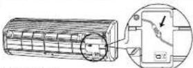
Wiring Of The Indoor Unit
- For wire connection of the indoor unit, you need to remove low cover and front cover.
Method to remove front cover.
- Refer to "FINAL STAGE OF INSTALLATION - How to Remove The Front Cover".
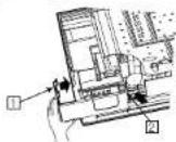
Method to remove the low cover
- Pull the cover at 1 and 2 in the directions as shown by arrows to remove the cover.
Wiring of The Outdoor Unit
- Please remove the side cover for wire connection.
- If you cannot attach the side cover due to the connecting cord, press the connecting cord in direction to the front panel to fl x it.
WARNING - Be sure that the hooks of the side cover is fixed in certainly. Otherwise water leakage may occur and this causes short circuit or faults.
- The connecting cord should not touch to service valve and pipes. (It becomes high temperature in heating operation.)
Checking for the electric source and the voltage range
Before installation, the power source must be checked and necessary wiring work must be completed. To make the wiring capacity proper, use the wire gauges list below for the load-in from a pole transformer and for the wiring from a switch board of luse box to the main switch and outdoor unit in consideration of the locked rotor current.
IMPORTANT
| Cable length | Wire cross-section |
| up to 6m | 1.6mm ^2 |
| up to 15m | 2.5mm ^2 |
| up to 25m | 4.0mm ^2 |

text_image
After remove the screw and cover, and put the connecting cords and it is the cover with screw.
text_image
A B C D Earth terminal D D- Investigate the power supply capacity and other electrical conditions at the installation location.
Depending on the model of room air conditioner to be installed, request the customer to make arrangements for the necessary electrical work etc.
The electrical work includes the wiring work up the outdoor. In localities where electrical conditions are poor, use of a voltage regulation is recommended.
CAUTION
Outdoor supply cords shall not be lighter than polychloroprene sheathed flexible cord with code designation 60245 IEC 57.
| IMPORTANT | For RAC-14LH1 only |
| Fuse Capacity | Fuse Capacity |
| 10A time delay fuse | 15A time delay fuse |
1 Insulation And Maintenance Of Pipe Connection
- The connected terminals should be completely sealed with heat insulator and then tied up with rubber strap.
- Please tie the pipe and power line together with vinyl tape as shown in the 1 figure showing the installation of Indoor and Outdoor units. Then fix their position with holders.
- To enhance the heat insulation and to prevent water condensation, please cover the outdoor part of the drain hose and pipe with insulation pipe.
- Completely seal any gap with putty.
Insulation material for pipe connection

3 Power Source And Operation Test
Power Source
CAUTION
- Please use a new socket. Accident may occur due to the use of old socket because of poor contact.
- Please plug in and then remove the plug for 2 - 3 times. This is to ensure that the plug is completely plugged into the socket.
- Keep additional length for the power cord and do not render the plug under external force as this may cause poor contact.
- Do not fix the power cord with U-shape nail.
2 Installation Of Remote Controller
- The remote controller can be placed in its holder which is tied on wall or beam.
To operate the remote controller at its holder, please ensure that the unit can receive signal transmitted from the controller at the place where the holder is to be fixed. The unit will beep when signal is received from the remote controller. The signal transmission is weaken by the fluorescent light. Therefore, during the installation of the remote control holder, please switch on the light, even during day time, to determine the mounting location of the holder.
The controller must be hooked onto the hook at the lower part of the holder. Push in the remote controller in the direction as shown in figure below.

Operation Test
- Please ensure that the air conditioner is in normal operating condition during the operation test. - Explain to your customer the proper operation procedures as described in the user's manual.
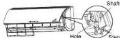
How to Remove The Front Cover
1 Remove the front panel.
- Please remove and attach the front panel by both hands.

• After opening the front panel by both hands.
① Undo the right arm while pushing it inside.
② Slide the front panel to right as shown in figure. Then remove while pulling it to front.
2 Remove the filters.
3 Open the electrical cover. Disconnect the wire connector.

4 After removing two screws, pull the center of the front cover towards you and release the claws.
5 Pull the side faces (lower sections) of the front cover towards you as shown in the figure and remove the cover.
How to Attach the Front Cover
1 Check that the drain pan is securely attached
2 After installing the front cover onto the unit, hook three claws at upper side of the cover securely. Then, push the center of the front cover to lock the claws.
3 Tighten the two screws.

4 Connect the wire connector. Close the electrical cover.
5 Install the filler.
6 Slide the shafts of the right and left arms on the washable panel along the steps to insert the shafts into the holes till they stop. After checking that the shafts are securely inserted, close the panel.