30-1 - I pakategorizuar EBSO - Manual falas për përdoruesin
Gjeni manualet e pajisjes falas 30-1 EBSO në format PDF.

Pyetjet e përdoruesve rreth 30-1 EBSO
0 pyetje rreth kësaj pajisjeje. Përgjigjuni atyre që njihni ose bëni tuajin.
Bëni një pyetje të re rreth kësaj pajisjeje
Shkarko udhëzimet për tuajin I pakategorizuar në format PDF falas! Gjeni manualin tuaj 30-1 - EBSO dhe merrni pajisjen tuaj elektronike sërish në duar. Në këtë faqe janë publikuar të gjitha dokumentet e nevojshme për përdorimin e pajisjes suaj. 30-1 e markës EBSO.
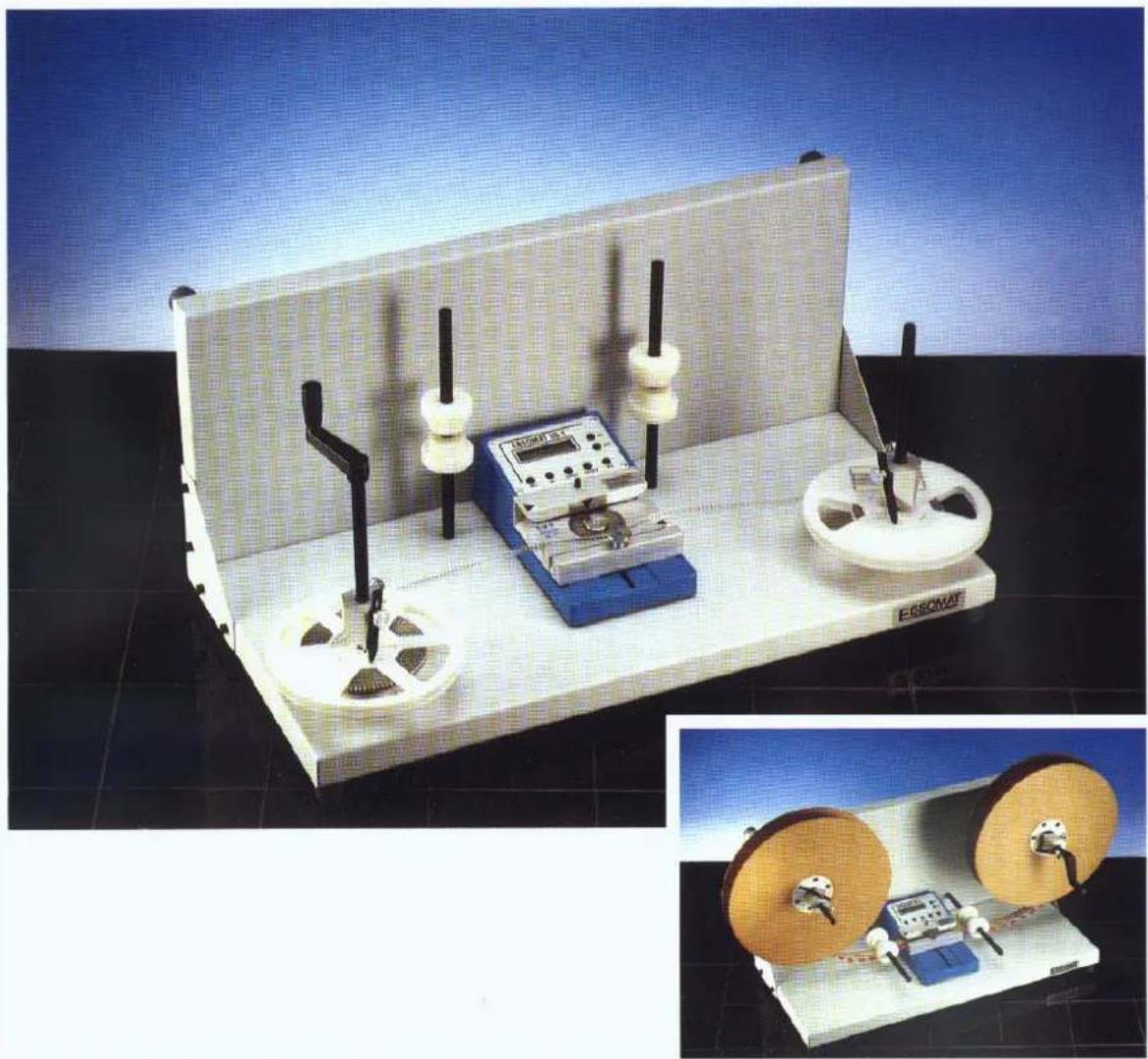
MANUAL I PËRDORUESIT 30-1 EBSO
Ebsom at 30-1
Bedi enu ng sanl ei tu ng Gru ndg erät
Operati ng manual basi c uni t
natural_image
Two experimental optical devices: one with a ruler and test chamber, the other with two spools of tape (no visible text or symbols)Masch i nennu mmer / Mach i ne nu mber:
Ebsom at 30-1
Herstel I er: DEBSO Gm bH
I ndu stri estr. 15
DD-7 6 7 6 7 Hag enbach
DTel .:(0049)07273/9358-0
DF ax: ( 004 9) 07 27 3 /93 5 8 -28
DE-Mai l : i nfo@Debso.com
DI nternet : http://www.ebso.com
Ebsomat 30-1
I nh al tsv erz ei ch ni s
Sicherheitshinweise 4
Technische Daten 5
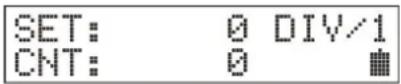
Gerät einschalten....6
Stü ckzahlvorwahl 6
Faktoreinstellung....7
Zählvorgang....8
Arbeiten mit dem SMD-Adapter 8
Kontrolle der Versorgungsspannug....9
Empfohlene Ersatzteile....12
Table of content
Technical Data: 14
Switching on 15
Preset target count.... 15
Setting the factor 16
Count process 16
Working with the SMD-Adapter 17
Supply voltage monitoring....17
Battery-Menu 18
Display-Menu....18
Instructions of the Operation of Counter EBSOMAT 30-1 19
Wiring Diagram....20
Recommend spare parts: 21

Sicherheitshinweise
W i cht i g !!!
Bittel esen Sie zu erst die Bedi enungsanleitung, bevor Sie mit dem Zusammenbau der Maschine und dem Einsatz in der Produktion beginnen.
Der Ebsomat 30-1 darf nur zur Zählung der Anschlussbeinchen von elektronischen Bau bei I en verwendet werden.
Bau tei l e i mmer nu r mi t dem daf ü r vorg eseh enen Adapter z ä h l en. Ebenso darauf ach ten, dass der Ansch l ag ri ch ti g ei ng estel l t i st.
Schü tzen Sie das Gerät vor Flüssigkeiten sowie extremen Temperaturen.
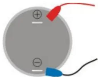
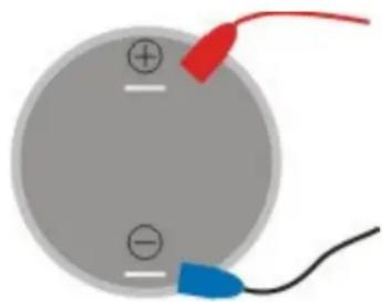
Beim Tausch des Akkumulators auf die richtige Polung achten! Eine Verpolung kann das Gerät beschädigen! Die Kontakte nicht kurzschließen!
natural_image
Simple diagram of a circular component with two labeled terminals and a red and blue clip attached to its side (no text or symbols)Der Akkumulator ist bleihaltig, bitte ü ber Batteriesammelstellen entsorgen.

natural_image
Two green recycling symbols: a trash bin with no waste and a recycling symbol (no text or labels)Technische Daten:
Maße und Gewichte
Zähler ohne SMD-Adapter D D D D240 x 140 x 80 mm 2,0 kg
Zähler mit SMD-Adapter D D D D240 x 140 x 80 mm 2,1 kg
Anschl ussdat en
Netzteil
230 V 50-60 Hz
Ak k u betri eb ( 1 x 2V Bl ei ak k u ) D D D16 Std. Laufzei t
Leistung und Ausstattung
- Vorwärts- und Rück wärtszähung bis zu 20000 Impul sen / Sekunde
- ei nstel I barer Tei I u ng sfak tor ( meh rere Bei nch en oder Gu rtl öch er pro Bau tei I ) 1 bi s 9
- ei nstel I barer Mul ti pl i k ati onsfak tor ( meh rere Bau tei I e pro Gu rtl och ) 1 bi s 9
- Vorwahl der Zi el -Stückzahl bis 999999 möglich
- ak u sti sch es Si g nal bei m Errei ch en der St ü ck z ah l
- Mark i erung des Gurtes bei erreichter Stück zahl durch Gurtmark i erer
- Anzei g e des Ak kul adez u standes
- bequ em bedi enbare Menü s zum Einstel I en des Sol I wertes, des Fak tors, des Anzeig ek ontrastes sowie Ak kudi agnosti k
Achtung!
Wenn nach dem Ei nschal ten di e Mel duensor error ersch ei nt, k ann es sei n, dass der L ich tsch rankensch l i tz v ersch mut z t i st, oder der SMD Adapter an Ei ner u ng ü nsti g en Posi ti on steht.
Bitte durch leichtes Ausblasen reinigen oder SMD Adapter leicht verschieben.
Zum Testen der Lichtschranke (ohne SMD-Adapter, falls Sie mit dem SMD-Adapter arbeiten, diesen vor dem Test nach unten schieben, da die Zähne die Lichtschranke irritieren können) die Tasten
SET + INPUT gedrückt halten und das Gerät einschalten, Test läuft, Ergebnis wird angezeigt. Bei Sensor error bitte die Lichtschranke reinigen.
Für einen automatischen Test der Lichtschranke bei jedem einschalten können Sie bei der Anzeige im Display: Test ok, mit der Taste set von manuell auf Automatik umstellen und mit reset bestätigen, auf dem Display ist dann angezeigt:
Test ok,
set: au to reset
Gerät einschalten
Drück en Si e di e Taste ON. Das Gerät mel det si ch mi t Anzei ge der Versi onsnummer und kurzem akustisch en Signal. Di el etz te Gerätek onfi gurati on ersch ei nt auf dem Bildschirm.
D D D D
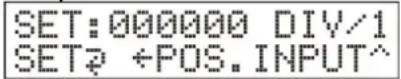
St ückzahl vor wahl
Drücken Sie die Taste SET. Im Display blinkt die letzte Stelle von Zielstückzahl und zeigt an, dass der Zahl er zur Einstellung der Vorwahl bereit ist.
D D

Mit der Pfeiltaste ← springen Sie an die Position der Zahl, welche Sie ändern wollen. Nun können Sie mit der Taste INPUT die Ziffer erhöhen durch mehrfaches Tippen. Für die nächsten Stell en gehen Sie genau so vor.
Durch Drücken der Taste RESET können Sie die gesamte Vorwahl auf Null setzten. Nach kompletter Eingabe die Taste SET drücken, nun ist Ihre Vorwahl eingegeben.
Bei spi el : Stück zahl von 1000 auf 13 00 ändern:
SET drü cken um ins Stü ckzahlmenü zu gelangen, ← drei mal drü cken – Cursor i st j etzt auf Hunderter-Posi ti on, INPUT dreimal drü cken – Anzeige ist jetzt 001300, mi t SET absch l i eßen.
Bei spiel : Stück zahl von 125 00 auf 50 ändern:
D DSET drü ck en – Stü ck zahl menü ersch ei nt, mi t RESET di e Anzei g e auf Null stell en, ← ei nmal drü ck en, INPUT fü nfmal drü cken – Anzeige zeigt 000050 an, z u m Hau ptmenü mi t SET.
Faktoreinstellung
Taste, DI V' drück en. I m Di spl ay ersch ei nt:

Mi t der Pfei l taste ← wechsel n Si e z wi sch en Mul ti pl i k ati ons- und Teil u ng smodu
- bei mehreren Beinchen (oder Gurtlöchern) pro Bauteil wählen Sie den Teilungsfaktor – DI V/
- bei mehreren Bauteilen pro Gurtloch wählen Sie Multiplikationsfaktor – MUL* Nun mit Hilfe der Taste INPUT den gewü nschten Teiler einstellen. Durch drücken der Taste DIV wird der Faktor ü bernommen.
Beispiel: Teilungsfaktor von 3 auf 2 ändern:
DI V drü ck en – Fak tormenü ersch ei nt, mi t RESET auf 1 z u rü ck setz en, mit INPUT auf 2 erhöhen, mi t DI V bestätigen.
Beispiel: Teilungsfaktor 2 auf Multiplikatorsfaktor 2 ändern:
DI V drück en – Fak tormenü ersch ei nt, ← drücken – Anzeige oben rechts ändert von DIV auf MUL, beim Moduswechsel wird der Faktor auf 1 zurü ckgesetzt, deshalb mit INPUT auf 2 erhöhen, mi t DI V dieses Menü v erl assen.
Zähl vorgang
Stell en Si e di eri ch ti ge Gu rtbrei te z wi sch en Li ch tsch rank endu rch gang und Ansci ei n.
Bitte immer etwas Spiel zwischen Anschlag und Lichtsch rank endurchgang l'asseri ca. 5 mm.
Ach ten Si e darauf, dass bei ax i al en Bau tei I en der Absatz, wie auf der Ti tel sei te gez ei g t, zum Li ch tsch rank endurch gang zeigt.
Bei radi al en Bau tei I en den Anschlag um 180° dreh en.
Stel I en Si e di e Zi el stü ck z ahl und Anz ahl der Bei nchen wi e vorher besch rieber Zi eh en Si e den Gurt nu n v on l i nk s nach rechts dur ch den oben besch riebenen Zwi sch enrau m.
Der Zähl er erhöh t den Zähl wert, wenn man das Bau tei I von link s nach rechts beweg und verri ng ert den Zähl wert i n di e entg eg eng esetz te Ri ch tung. Di es verh indert ei fal sch en Zähl wert, fal l s bei m Durch zi eh en ei ni g e Bau tei I e verseh entl i ch i nd Ri ch tung gez og en werden.
Der Summer ertönt bei Stück zahl en außerhalb des Zähl bereichs, d.h. bei negativ e Zahl en und Zahl en über dem eingestel ten Zi el wert.
Der Summer und die erreichte Stückzahl werden durch die Taste RESET wieder z u r ü ck g esetz t.
An dieser Stell e können Sie nun den Gurt durch den Gurtmark i erer mark i eren und anschließend mit einer Schere an dieser Stell e absch nei den.
Ar beiten mTit demT SMD-Adapter
Bei der Zählung von SMD-Bau teilen mit Hilfe des Adapters (Opti on) werden anstatt bei nach die sich im Gucht befinl ich en Löchergezählt, d.h. Si e müssen die Löcher im Gucht pro Bau teilen und als Teilungsfakt vor ein-gen eben.
Bei kI ei nen SMD-Bau formen si nd u mg ek eh rt meh rere Bau tei I e pro Loch mög l ich, i n di esem Fal I geben Si e den entsprech enden Mul ti pl i k ati onsfak tor ei n.
- Anschlag durch Öffnen der Rändel sch rau bei lösen
- Anschlag nach hinten schieben
- Rändel sch rau be am SMA-Adapter h erau ssch rau ben
- SMD-Adapter mit dem Zahnrad nach vorne in den Bauteilezähler einsetzen (si eh e Ti tel sei te)
- SMD Adapter mit Gerät festhalten und umdrehen, die Rändelschraube einsetz en und festsch rau ben ( Geräteu ntersei te)
- Mit der Taste DIV die Anzahl der Gurtlöcher pro SMD-Bauteil eingeben
- Vorwahl ei ng eben wi e v orh er besch ri eben
- Gurt nu n v on rechts nach links durch den Adapter ziehen
- Bei SMD-Gurten keine Markierung möglich
Kontrolle der Versorgungsspannug
In der rechten unteren Eck e des Di spl ay s wi rd ei n Sy mbol ei ng ebl endet, das Si e ü den Batteri estatu s i nformi ert.
Sobal d ei n Netz gerät ang eschl ossen wi rd, ersch e nt hi er D, al s S y mbol f ü r Netz gerätsteck er.
WDi rd der Netz anschl u ss getrennt, ze i g t h i er ei n Sy mbol den Ak k u l adez u stand:
D-Akkui st vol l
D-75%
D-50%
D-25%
D- Ak k u fast l eer
D- ( Symbol bl i nk t) – ca. 8 Minu ten bi s zu automati sch er Absch al tu ng
- (Symbol blinkt + akustisches Signal) – ca. 4 Minuten bis zur Abschaltung
☐ - (in der ersten Zeile die Meldung Battery empty) – ca. 30 Sekunden, um I au fende Charge zu beenden, danach sch al tet das Gerät ab.
Es wi rd empfohl en, den Ak k u so sch nel l wi e mög l i ch wi eder aufz ul aden, d.h. bere bei Anzei ge , 75%.
Di eses Ak k u besi tz t k ei n Memory -Effek t, öfteres Nach l aden v erl äng ert dessen Lebensdau er.
Das Gerät darf an das Netz tei I ständig angeschlossen bl ei ben.
Ak ku-Menü
Um genau ere Informati onen ü ber den Ak k u statu s z u erh al ten, dr ü ck en Si e g l ei ch z e SET und DIV. Es erscheint folgender Bildschirm:

Es wi rd di e ak tu el l e Ak k u spannu ng angez ei gt,
der Ladestrom + ×××mH bz w. Entl adestrom ×××mH
bei m Laden ei n Hi nwei s CHARGINGÖ oder tery full
Zu rü ck z u m Hauptmenü mit der Taste RESET.
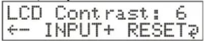
Di s play -Men ü
Den Anzeigekontrast können Sie einstellen, indem Sie die Tasten SET und RESET g l ei ch z ei ti g dr ü ck en. Es ersch ei nt:

Mit jedem Druck auf die Taste ← wird die Anzeige heller, mit Taste INPUT wird sie dunk I er.
Mit der Taste RESET kommen Sie zurück zum Hauptmenü.
Hinweis zur Behandlung der BLEI -Akkus im T EBSOM
Di eses Gerät hat al s Spannu ng sv ersoru ng ei nen Bl ei ak k u mul ator. Durch Tiefentladung dieses Akkumulators oder Verpolung der Anschlü sse kann der Ak ku mul ator ei nen ni ch t reparabl en Sch aden erl ei den.
Dem können Si e v orbeu g en, indem Si e
- den Zähler immer dann ausschalten, wenn er nicht mehr gebraucht wird,
- bei Ni ch tg ebrau ch i mmer an das L adeg erät ansch l i eß en
- das Gerät niemals länger als drei Monate ohne Nachladung stehen lassen
Akkus unterliegen, bedingt durch Ihre Bauart, einem Verschleiß (Verbrauchsmaterial). Die Lebensdauer eines Akkus ist auch abhängig von der richtigen Behandlung. Die entscheidenden Faktoren sind die Lade- und Entladevorgänge. Um die Lebensdauer so lange wie möglich aufrecht zu erhalten, sollten die obigen Hinweise unbedingt beach tet werden.
Der Akku ist ein Verbrauchsmaterial und hat auch bei richtiger Behandlung nur eine beg renz te Lebensdau er.
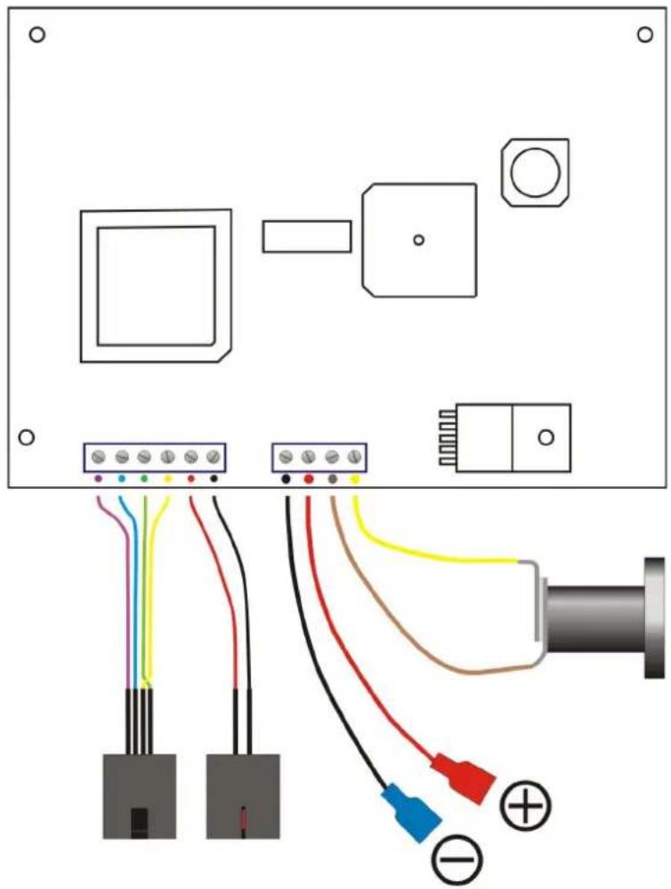
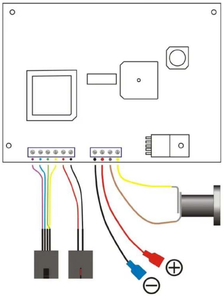
Verdrahtungsplan
Verdrahtungsplan / wiring diagram
natural_image
Electrical wiring diagram showing connections between components including connectors, sensors, and a pipe (no text or symbols present)Em pfohlene Ersatzteile
| Bezei ch nu ng DArti k el nu mmer | |
| Dru ck k nopf D3 0-1/0000/014 | |
| El ek troni k kompl ett D3 0-1/4 900/027 | |
| Netz tei l D3 0-1/4 900/028 | |
| Bl ei Ak ku | 3 0-1/4 900/029 |

Safety precautions
I m portant !!!
At first please read the operating instructions, before starting to assembly the machine and to operate i t.
The Ebsomat 30-1 may only be used for counting the leads of electronic components.
Cauti on!
Count the components always only with the adapter which belongs to it.
Also you must pay attention to the stopper being adjusted in the right way.
Protect this device against intrusion of fluids and extreme temperatures.
On replacing the battery connect it in proper direction according to the (+) and (-) poles! Reverse connection may destroy this device! Do not short the poles!
natural_image
Simple diagram of a circular component with labeled terminals and colored wires (no text or symbols)The battery contains lead; please return to battery collecting point.

natural_image
Symbol of a trash bin crossed with no text or labels
natural_image
Green recycling symbol with four chasing arrows forming a triangle (no text or symbols)Technical Data:
DimTensions and WTeights
Counter without SMD-Adapter
240 x 140 x 80 mm 2.0 kg
Counter with SMD-Adapter
240 x 140 x 80 mm 2.1 kg
Connections
Charger
230 V 50-60 Hz
Battery (1 x 2V lead accumulator)
16 hours capacity
Capacity and EquipmTent
- forward and backward counting up to 20000 pulses / second
- adjustable divisor (multiple pins or tape holes per component) up to 9
- adj u stabl e mul ti pl i er ( mul ti pl e components per tape h ol e) u p to 9
- presel ecti on of nu mber to be counted, u p to 999999 possi bl e
- acousti cal si g nal on crossi ng the targ et count
- with a tape marker you can mark the tape after the preset number is reached
- easy to use menus for setting the target, factor, LCD-contrast and battery di ag nosti cs
Caut i on!
If you see the message Sensor error, it is possible that the light barrier slot is dirty or the SMD Adapter is on a bad position.
Please clean with air by blowing or move SMD adapter and switch on the counter again.
Test light barrier:
without SMD-Adapter:
Press key SET and INPUT when turn on the counter, test is running.
On Di spl ay show: T t est ok
Set : mTan. T TReset : ↗ ↗
You can count yourcomTponents.
Display show: sensor error, please blow out the light barrier.
For change from manual modus in automati cal modus (only with out SMD-Adapter, because the tooth are irritates the light barrier)
Di spl ay show: Dtest ok
Set: man. D Dreset: ↩ ↗
To change in au tomati c modu s: press key set and confi rm wi th reset.
Di spl ay show: T t est ok
TSet: auto. TReset:
Swi t chi ng on
Switch the machine on with key ON. The counter shows the version number and produces a short beep. The last unit configuration used appears in the display.

Preset target count
Push key SET. In the display flashes the last position of SET and indicates the counter being ready for preset.
With the arrow key ← you move to the decimal position you want to set.
Now you may set the digit with key INPUT, push repeatedly to advance it.
Do the same with the other digits you want to change.
Pushing RESET sets the whole count to zero.
Push key SET after the complete input. Now your target count is saved in memory.
Example: Changing preset from 1000 to 1300:
push SET to reach the preset menu,
push ← th ree ti mes – cursor i s on the h undreds posi ti on now,
push INPUT three times – display shows 001300,
store and leave with SET.
Example: Changing preset from 12500 to 50:
push SET – preset menu is active,
witch RESET is the display 000000 now,
push ← once,
push INPUT five times – display shows 000050,
back to mai n menu with SET.
Setting the factor
Push the key DI V. The display shows:

The key can be used to switch over between multi play and divide mode.
- Don several pi ns ( or tape hol es) per component choose di vi sor – DI V/
- Don several components per tape h ol e choose mul ti pl i er - MUL *
Now set the desired factor with the key INPUT.
Pushi ng DI V will store this factor.
Example: Changing the divisor factor from 3 to 2:
press DI V – factor menu appears,
with RESET set to 1,
increment with INPUT to 2,
confi rm wi th DI V.
Example: Changing the divisor factor 2 to multi play factor 2:
press DI V – factor menu appears,
press ← – display in the right top corner changes from DIV to MUL,
on mode change factor will be automatically set to 1, therefore
with INPUT increment to 2,
I eave this menu with DI V.
Count process
Adj u st the correct tape breadth between l i g h t barri er sl ot and stopper. P l ease l et al ways s a l i ttl e b i t space of approx . 5 mm between stopper and l i g h t barri er sl ot.
PI ease be careful when treating axial components, the mill ed part points to the l i g barrier slot, as shown on the cover.
I f y ou want treat radi al components, y ou must turn the stopper for 180 degrees.
Now set the targ et count and the number of leads one component has as described above.
Pull now the tape from left to the right through the gap. The counter counts forwards and back wards.
Therefore the counting result is all ways s correct, even if you pull the tape in the wro direction.
The buzzer sounds on counter results which are out of range, i.e. on negative counts and counts above the presetted target count. When the target count is reached, you can mark the tape with the tape marker. Later you can cut the tape on marked position with scissors.
Through key RESET you may set back the buzzer and the counter result.
WTorking with the SMD-Adapter
By counting SMD-components with the adapter (opti on), not the leads will be counted but the holes in the tape. That means you must count the holes per component (or components per hole) and preset this count using the DI V key.
- DI oose the stopper by I ooseni ng the k nurl ed screw
- Dsl i de stopper to the back
- DI loose knurl ed screw on the SMA-adapter
- set the SMD-Adapter into the counter with the toothed wheel in front (see cover)
- hold on the SMD-adapter and the 30-1, turn it and screw in the knurled screw
- set the number of holes per SMD-component with the key DIV as described above
- set the target count with the key SET as described above
- Dnow pull the tape from right to the left side through the adapter
- Don SMD-tapes you can't mark
Supply voltage monitoring
The display shows on the right side a symbol indicator which informs you about the state of the battery.
Connected external power supply is indicated with Ⓞ, a symbol for the power plug.
On disconnected power supply shows a symbol the charge state:
- battery is full
-75%
-50%
-25%
☐ - battery al most empty - ( symbol fl ash es) – approx . 8 mi nu tes to au tomati c sh u t-off
☐ - (symbol flashes + buzzer sounds periodically) – approx. 4 minutes to shut-off
☐ - (message Battery empty in the first line) – approx. 30 seconds to fi ni sh actual counting, than au tomati c shut-off.
It is recommended to rech arg e the battery as soon as possi ble, al ready on the 75% level.
This battery has no memory-effect, and frequently recharging extends the battery ifeti me. The device can remain connected to the power supply.
Battery-Menu
Push simultaneously keys SET and DIV to get more information about the battery state. Fol I owi ng di spl ay appears:

The actual battery vol tag e i s di spl ay ed,
ch arg e current+ ×××mH or di sch arg e current×××mH
while charging a message CHARGING Battery full
Back to main menu with the key RESET.
Di s p l ay -M e n u
Pushing simultaneously the keys SET and RESET allows you to set the display contrast. The display shows:
With every push on key ← the display will be brighter, and with key INPUT darker. Back to main menu with the key RESET.
Instructions of the Operation of Counter EBSOMAT 30-1
This device has a lead accumulator as voltage supply. Through discharge of this accumulator or poling of the supplies the accumulator may suffer no repairable damage.
You could prevent this by
- al ways switching off the counter if it is not used
- al ways connecting the counter to the charger if it is not used
■ never leaving the counter with outrech arg e for more than 3 month s
Accu mul ators are subject to wear (consumptive material) due to their construction. The i fe-span of an accu mul ator so depends on correct handling. The crucial factor are charged and discharged processes. To maintain the i fe-span as long as possible please observe above advice for ni tel y. The accu mul ator is a consumptive material and has only a limited i fe-span even with correct handling.
W i r i n g Di a g r a m
Verdrahtungsplan / wiring diagram
natural_image
Electrical wiring diagram showing connections between components including connectors, sensors, and a pipe (no text or symbols present)Recommendspareparts:
| description part -nr. | |
| pressure button 30-1/ 0000/ 014 | |
| electronic complete 30-1/ 4900/ 027 | |
| battery charger 30-1/ 4900/ 028 | |
| sealed - lead rechargeable battery | 30-1/ 4900/ 029 |