JBNK1700QC - Klimatizues LG - Manual falas për përdoruesin
Gjeni manualet e pajisjes falas JBNK1700QC LG në format PDF.

Pyetjet e përdoruesve rreth JBNK1700QC LG
0 pyetje rreth kësaj pajisjeje. Përgjigjuni atyre që njihni ose bëni tuajin.
Bëni një pyetje të re rreth kësaj pajisjeje
Shkarko udhëzimet për tuajin Klimatizues në format PDF falas! Gjeni manualin tuaj JBNK1700QC - LG dhe merrni pajisjen tuaj elektronike sërish në duar. Në këtë faqe janë publikuar të gjitha dokumentet e nevojshme për përdorimin e pajisjes suaj. JBNK1700QC e markës LG.
MANUAL I PËRDORUESIT JBNK1700QC LG

LG
Life's Good
LG
text_image
Scanned document header with logo, QR code, and UI elements including LG, Twitter, and Facebook icons
natural_image
Blank gray image with no visible content, text, or symbols

natural_image
Three horizontal gray gradient bars with no text or symbols
natural_image
Line drawing of four people interacting, no text or symbols present
△


natural_image
Simple diagram with a warning symbol and two dots, no text or labels present
WARNING
Installation
Do not use a defective or underrated circuit breaker. Use this appliance on a dedicated circuit.
• There is risk of fire or electric shock.
For electrical work, contact the dealer, seller, a qualified electrician, or an Authorized Service Center.
- Do not disassemble or repair the product. There is risk of fire or electric shock.
Always ground the product.
• There is risk of fire or electric shock.

text_image
Illustration showing a person giving a thumbs-up while another person holds a phone, with a prohibition symbol below.
Install the panel and the cover of control box securely.
• There is risk of fire or electric shock.
Always install a dedicated circuit and breaker.
- Improper wiring or installation may cause fire or electric shock
Use the correctly rated breaker or fuse.
• There is risk of fire or electric shock.
Do not modify or extend the power cable.
• There is risk of fire or electric shock.

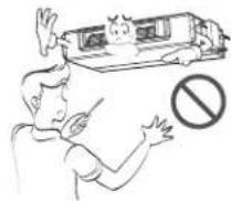
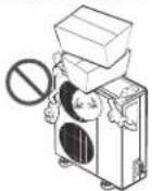
Do not install, remove, or re-install the unit by yourself (customer).
- There is risk of fire, electric shock, explosion, or injury.
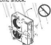
Be cautious when unpacking and installing the product.
- Sharp edges could cause injury. Be especially careful of the case edges and the fins on the condenser and evaporator.

For installation, always contact the dealer or an Authorized Service Center.
• There is risk of fire, electric shock, explosion, or injury.
natural_image
Illustration of a person in a thought bubble and a person at a desk with an exclamation mark (no text or symbols present)Do not install the product on a defective installation stand.
- It may cause injury, accident, or damage to the product.

natural_image
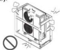
Illustration of a distressed air conditioner unit with a circular symbol below, no text or symbols presentBe sure the installation area does not deteriorate with age.
- If the base collapses, the air conditioner could fall with it, causing property damage, product failure, and personal injury.
Operation
Do not let the air conditioner run for a long time when the humidity is very high and a door or a window is left open.
- Moisture may condense and wet or damage furniture.

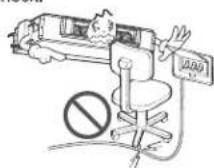
Do not plug or unplug the power supply plug during operation.
• There is risk of fire or electric shock.

Do not allow water to run into electric parts.
- It may cause There is risk of fire, failure of the product, or electric shock.
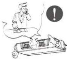
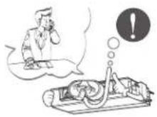
When flammable gas leaks, turn off the gas and open a window for ventilation before turn the product on.
- Do not use the telephone or turn switches on or off. There is risk of explosion or fire

Take care to ensure that power cable could not be pulled out or damaged during operation.
• There is risk of fire or electric shock.

text_image
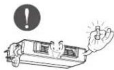
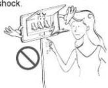
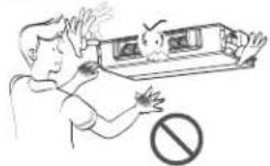
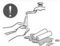
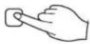
lockDo not touch(operate) the product with wet hands.
• There is risk of fire or electrical shock.
text_image
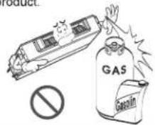
shock.Do not store or use flammable gas or combustibles near the product.
• There is risk of fire or failure of product.
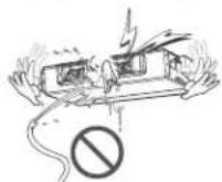
If strange sounds, or small or smoke comes from product. Turn the breaker off or disconnect the power supply cable.
- There is risk of electric shock or fire.
Do not place anything on the power cable.
• There is risk of fire or electric shock.
Do not place a heater or other appliances near the power cable.
- There is risk of fire and electric shock.

Do not use the product in a tightly closed space for a long time.
• Oxygen deficiency could occur.

Stop operation and close the window in storm or hurricane. If possible, remove the product from the window before the hurricane arrives.
• There is risk of property damage, failure of product, or electric shock.

Do not open the inlet grill of the product during operation. (Do not touch the electrostatic filter, if the unit is so equipped.)
• There is risk of physical injury, electric shock, or product failure.
When the product is soaked (flooded or submerged), contact an Authorized Service Center.
• There is risk of fire or electric shock.
Be cautious that water could not enter the product.
• There is risk of fire, electric shock, or product damage.
Ventilate the product from time to time when operating it together with a stove, etc.
• There is risk of fire or electric shock.

Turn the main power off when cleaning or maintaining the product.
• There is risk of electric shock.

When the product is not be used for a long time, disconnect the power supply plug or turn off the breaker.
- There is risk of product damage or failure, or unintended operation.

text_image
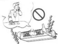
Cartoon illustration showing a person looking at a computer screen with an exclamation mark and a warning symbol, while another person looks on in concern.Take care to ensure that nobody could step on or fall onto the outdoor unit.
• This could result in personal injury and product damage.

CAUTION
■ Installation
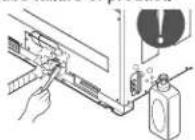
Always check for gas (refrigerant) leakage after installation or repair of product.
- Low refrigerant levels may cause failure of product.
Install the drain hose to ensure that water is drained away properly.
• A bad connection may cause water leakage.
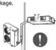
Keep level even when installing the product.
• To avoid vibration or water leakage.

Do not install the product where the noise or hot air from the outdoor unit could damage the neighborhoods.
- It may cause a problem for your neighbors.

Use two or more people to lift and transport the product.
- Avoid personal injury.
Do not install the product where it will be exposed to sea wind (salt spray) directly.
- It may cause corrosion on the product. Corrosion, particularly on the condenser and evaporator fins, could cause product malfunction or inefficient operation.

text_image
Safety warning sign with Chinese characters and a prohibition symbol, depicting outdoor safety monitoring setupOperation
Do not expose the skin directly to cool air for long periods of time. (Don't sit in the draft.)
• This could harm to your health.

Do not use the product for special purposes, such as preserving foods, works of art, etc. It is a consumer air conditioner, not a precision refrigeration system.
• There is risk of damage or loss of property.

text_image
Diagram illustrating a noise pollution experiment with labeled components including a no-smoking sign, smoke, and a plant.Do not block the inlet or outlet of air flow.
- It may cause product failure.

Use a soft cloth to clean. Do not use harsh detergents, solvents, etc.
• There is risk of fire, electric shock, or damage to the plastic parts of the product.

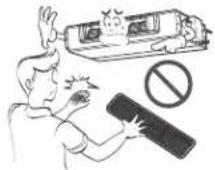
Do not touch the metal parts of the product when removing the air filter. They are very sharp!
• There is risk of personal injury.
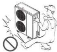
Do not step on or put anything on the product. (outdoor units)
• There is risk of personal injury and failure of product.
Always insert the filter securely. Clean the filter every two weeks or more often if necessary.
- A dirty filter reduces the efficiency of the air conditioner and could cause product malfunction or damage.

Do not insert hands or other objects through the air inlet or outlet while the product is operated.
• There are sharp and moving parts that could cause personal injury.

Do not drink the water drained from the product.
• It is not sanitary and could cause serious health issues.

Use a firm stool or ladder when cleaning or maintaining the product.
- Be careful and avoid personal injury.

Replace the all batteries in the remote control with new ones of the same type. Do not mix old and new batteries or different types of batteries.
• There is risk of fire or explosion

Do not recharge or disassemble the batteries. Do not dispose of batteries in a fire.
• They may burn or explode.

If the liquid from the batteries gets onto your skin or clothes, wash it well with clean water. Do not use the remote if the batteries have leaked.
• The chemicals in batteries could cause burns or other health hazards.
Prior to Operation
Preparing for operation
- Contact an installation specialist for installation.
- Use a dedicated circuit.
Usage
- Being exposed to direct airflow for an extended period of time could be hazardous to your health. Do not expose occupants, pets, or plants to direct airflow for extended periods of time.
- Due to the possibility of oxygen deficiency, ventilate the room when used together with stoves or other heating devices.
- Do not use this air conditioner for non-specified special purposes (e.g. preserving precision devices, food, pets, plants, and art objects). Such usage could damage the items.
Cleaning and maintenance
- Do not touch the metal parts of the unit when removing the filter. Injuries can occur when handling sharp metal edges.
- Do not use water to clean inside the air conditioner. Exposure to water can destroy the insulation, leading to possible electric shock.
- When cleaning the unit, first make sure that the power and breaker are turned off. The fan rotates at a very high speed during operation. There is a possibility of injury if the unit's power is accidentally triggered on while cleaning inner parts of the unit.
Service
For repair and maintenance, contact your authorized service dealer.

text_image
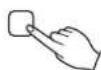
[AUTO RANG] [OPERATION] [SET TEMP] [FAN SPEED] [SUR FUCTOR] 1 2 3 4 5 6 7 8 9 10 11 12 13 14 15 16 17 18 19 20 21 22 23 24 25 26 27 28 29 30 31 32 33 34 35 36 37 38 39 40 41 42 43 44 45 46 47 48 49 50 51 52 53 54 55 56 57 58 59 60 61 62 63 64 65 66 67 68 69 70 71 72 73 74 75 76 77 78 79 80 81 82 83 84 85 86 87 88 89 90 91 92 93 94 95 96 97 98 99 100- Operation indication screen
- Wireless remote controller receiver
- 2ndF button
- Timer set/cancel Program/Week/Holiday Hour/Min/SET/Clr/ Ventilator
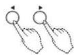
- Set temperature button
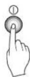
- ON/OFF button
- Fan operation
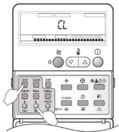
- Operation mode selection button
- Fan speed button
- Fan auto/Humidification button
- Room temperatur/filtersign release button
- Plasma/Heater button
- Time reset button
- Operation lamp
DUCT TYPE

text_image
P/N3650A2516DH Room Temperature Sensing: Remo. Indoor Unit 250(Nano, vindoor) Zone State/Default ESP V-Variable/Low ESP F-Hifed/High ESP V-Hifed/High ESP E.S.P. External Static Press Mode Select Cooling Only Heat Pump Group Control Select Single Control Group Control CAUTION On installing, don't impact to the PCB and LCD display. Don't remove the protection sheet. Use the specified screw. On installing, turn off the power.RESET switch
○ Room Temperature Sensing select Switch
- Use Remocon's sensor
- Use Indoor's sensor
- Use senor which has lower temperature between Remocon's and indoor's
○ Zone State/Default E.S.P
- Variable/Low E.S.P
- Fixed/High E.S.P
- Variable/High E.S.P
○ Mode select switch
- Cooling only
- Heat pump
○ Group control select switch
- Case of Single control
- Case of Group control
 |  |
 |  |
 |  |
 |  |
 | |
natural_image
Blank rectangular card with four horizontal bars and a small square at the bottom (no text or symbols)


flowchart
graph TD
    A[" "] --> B[" "]
    B --> C[" "]
    style A fill:#fff,stroke:#000
    style B fill:#fff,stroke:#000
    style C fill:#fff,stroke:#000
    note1["★"] above A
    note2["水"] below B
    note3["▲"] below C
text_image
88℃ Timer Cancel 2nd Program Wear Holding Set Ch PLASMA 10uF Min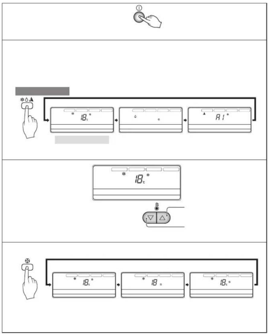
flowchart
graph TD
    A["①"] --> B["18°"]
    B --> C["18°*"]
    C --> D["R 1°"]
    D --> E["18°*"]
    E --> F["18°*"]
    F --> G["18°*"]
    G --> H["18°*"]
    H --> I["18°*"]

text_image
* 18° * 6° A 1°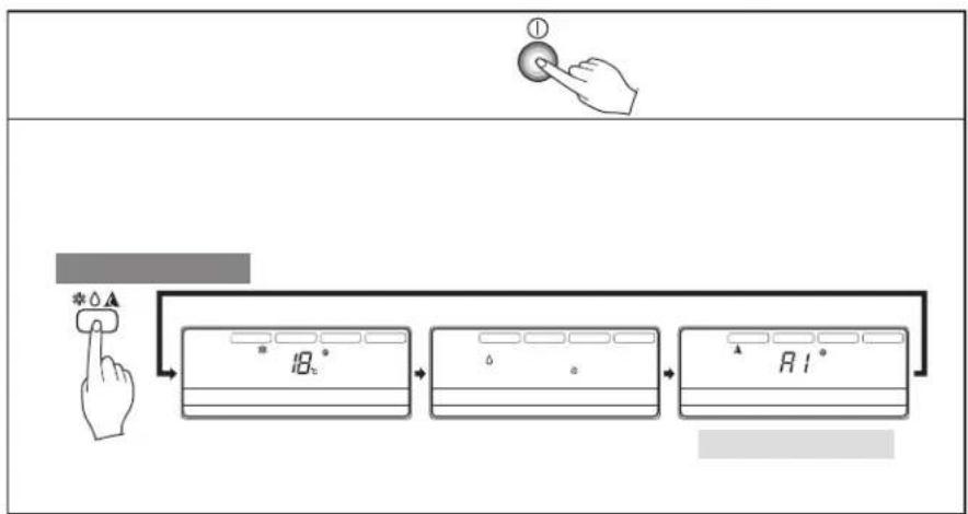
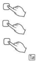
flowchart
graph TD
    A["Hand Press"] --> B["18°"]
    B --> C["18°"]
    C --> D["1°"]
    style A fill:#f9f,stroke:#333
    style D fill:#bbf,stroke:#333
 |
 |
 |
text_image
CL Timer Cancel 2nd + Program Week Holiday Set/CP Hour OK OK PLA/NA OK OK OK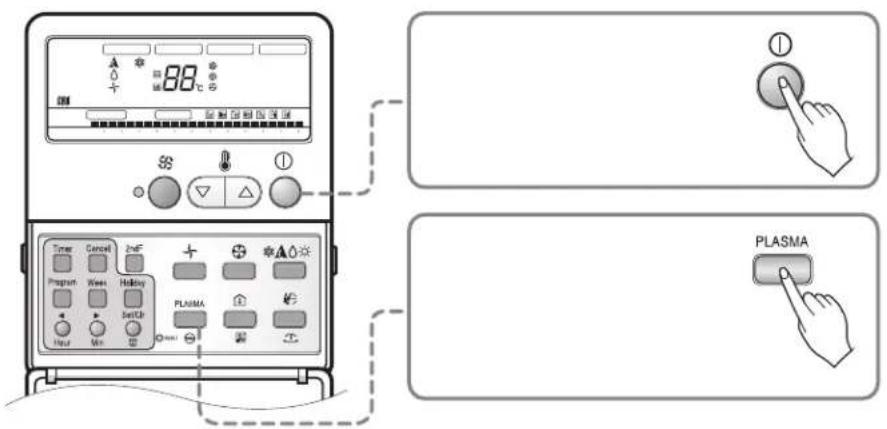
text_image
88°C Timer Cancel 2nF Program Week Holding PLASMA Plasma


text_image
23 Standard Semi 88 + + *▲○○ Program Week Holding SETC# PLANA Hour Min1 You can set the address up by pressing the Program button and the Set/Clr button about 3 seconds at the same time.
2 The group change uses the temperature control button to change the value possibly. The number of indoor unit uses the temperature control button to change the value possibly.
Ex) Group address: 2
Indoor unit number: 3
3 You can complete setting up the address by pressing the Program button and the Set/Cir button about 3 seconds at the same time.
- Multi model: Connect the outdoor unit and P1485 of outdoor unit
• Single model: Connect P1485 of outdoor unit - When you connect the indoor unit with central control unit, you should setup Network address which is recognized by central control unit inside of indoor unit.
• The address of central control is consisted by group number and number of indoor unit.
Note: The remote controller displays 'HL' if central controller has locked the remote controller.

text_image
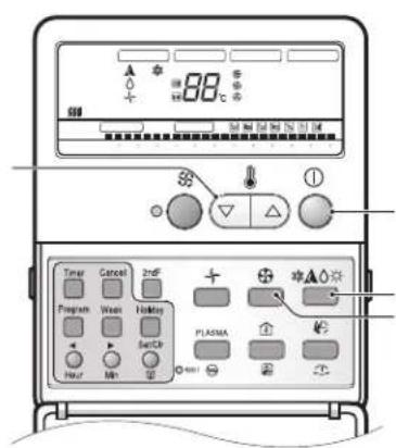
AUTO BANING OPERATION SET TEMP FAN SPEED REL FUNCTION 22℃ Timer Cancel InsF Program Mean Holiday Set Cl Hour Min PLACENA *▲○★ *▲○★1 If you press the room temperature button, room temperature will be indicated about 5 seconds. It will be returned to the desired temperature after 5 seconds.
- You can select the desired temperature for cooling operation from 16°C to 37°C and heating operation from 16°C to 30°C.
*There would be some difference between actual temperature you feel and room temperature of remote controller, because the temperature of the position is not uniform which the remote controller is located on.

text_image
Diagram illustrating a fluctuating trend with directional arrows and rating indicators below, featuring symbols like stars and squares.
natural_image
Cartoon illustration of a train emitting exhaust smoke (no text or symbols)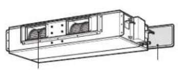
natural_image
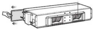
Technical line drawing of a mechanical housing or enclosure with ventilation grilles and mounting bracket (no text or symbols)
natural_image
Technical line drawing of a device with internal components and directional arrows indicating movement (no text or symbols)

natural_image
Grid pattern with a diagonal line and empty cells, no text or symbols present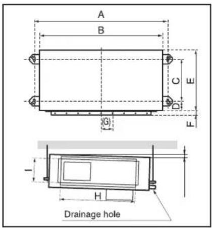
text_image
A B C D E F G H Drainage hole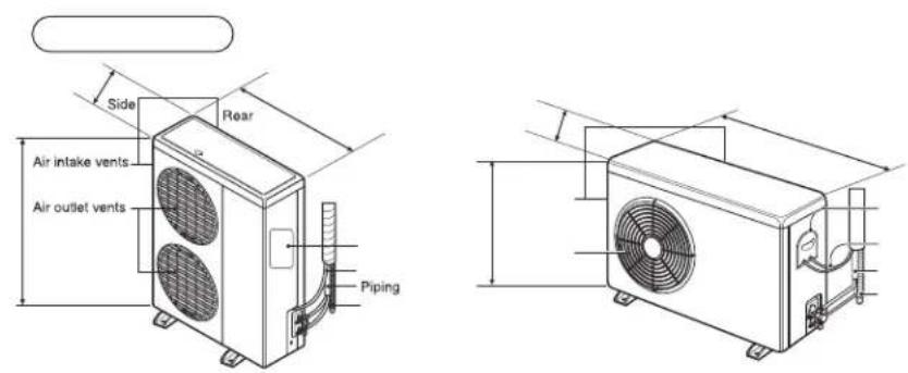
text_image
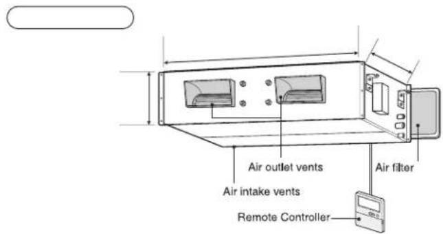
Air intake vents Air outlet vents Remote Controller Air filter
natural_image
Pure diagram of a warning sign with circular elements and an exclamation mark, no text or symbols present
natural_image
Two blank rectangular panels with abstract gray swirls and circular patterns on the top (no text or symbols)
natural_image
Two identical gray rectangular panels with abstract circular patterns on the left and right sides, no text or symbols present.
natural_image
Two horizontal gray panels with abstract circular patterns on the left and right (no text or symbols)
natural_image
Cartoon illustration of a boat with legs and arms, showing a person reacting to motion (no text or symbols)
text_image
Blank document layout with placeholder text boxes and a grid of gray rectangular blocks

natural_image
Pure electrical circuit lines without any symbols
flowchart
graph TD
    A["Module 1"] --> B["Connector"]
    B --> C["Connector"]
    C --> D["Connector"]
    D --> E["Switch"]
    E --> F["Device"]
    F --> G["Signal"]
    G --> H["Control Unit"]
    H --> I["Switch"]
    I --> J["Connector"]
    J --> K["Switch"]
    K --> L["Switch"]
    L --> M["Switch"]
    M --> N["Switch"]
    N --> O["Switch"]
    O --> P["Switch"]
    P --> Q["Switch"]
    Q --> R["Switch"]
    R --> S["Switch"]
    S --> T["Switch"]
    T --> U["Switch"]
    U --> V["Switch"]
    V --> W["Switch"]
    W --> X["Switch"]
    X --> Y["Switch"]
    Y --> Z["Switch"]
flowchart
graph TD
    A["Valve"] --> B["Pump"]
    B --> C["Control Unit"]
    C --> D["Valve"]
    D --> E["Pump"]
    E --> F["Control Unit"]
    F --> G["Valve"]
    G --> H["Pump"]
    H --> I["Control Unit"]
    I --> J["Valve"]
    J --> K["Pump"]
    K --> L["Control Unit"]
    L --> M["Valve"]
    M --> N["Pump"]
    N --> O["Control Unit"]
    O --> P["Valve"]
    P --> Q["Pump"]
    Q --> R["Control Unit"]
    R --> S["Valve"]
    S --> T["Pump"]
    T --> U["Control Unit"]

natural_image
Technical line drawing of a mechanical device with a pipe and fan assembly (no text or symbols)

natural_image
Technical line drawing of a traffic light device with a vertical pole and sensor arm (no text or symbols)
natural_image
Blank white image with a small black button at the bottom (no text or symbols)
text_image
Technical diagram of a bathroom sink assembly with labeled components and directional arrows indicating movement or force.
natural_image
Pure technical diagram showing mechanical components and alignment lines without any text, numbers, or symbols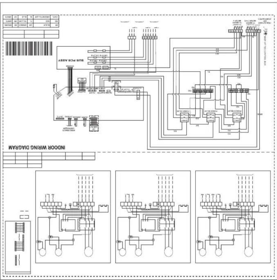
flowchart
graph TD
    A["Input"] --> B["Switch"]
    B --> C["Relays"]
    C --> D["M meters"]
    D --> E["Output"]
    style A fill:#f9f,stroke:#333
    style E fill:#bbf,stroke:#333

text_image
Electrical schematic diagram showing two electrical circuits with switches, relays, and wiring connections
flowchart
graph TD
    A["Input"] --> B["Component 1"]
    B --> C["Component 2"]
    C --> D["Component 3"]
    D --> E["Output"]

    subgraph Power Supply
        F["Input"] --> G["Component 1"]
        H["Component 2"] --> I["Component 3"]
    end

    subgraph Current Flow
        J["Current Source"] --> K["Current Output"]
    end

    subgraph Equipment Components
        L["Component 1"] --> M["Component 2"]
        N["Component 3"] --> O["Component 4"]
    end

    style A fill:#f9f,stroke:#333
    style H fill:#f9f,stroke:#333
    style J fill:#ccf,stroke:#333
    style L fill:#cfc,stroke:#333

text_image
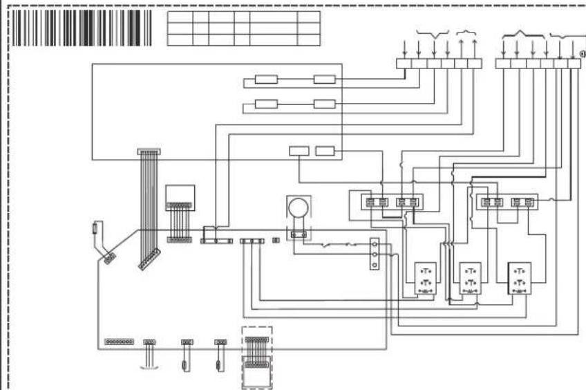
Electrical schematic diagram with labeled components and wiring connections, including grid layout and terminal block layout.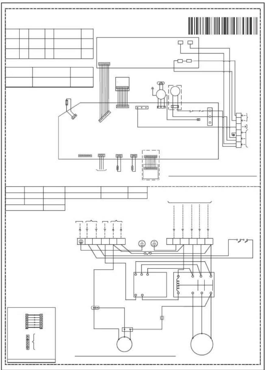
text_image
Electrical schematic diagram with labeled components and wiring connections, including panel layouts and component layout.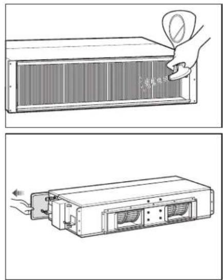
natural_image
Technical illustration showing two views of a heat exchanger with a hand inserting a fan into it (no text or symbols present)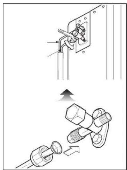
natural_image
Technical illustration showing two installation steps: one with a tool inserted into a socket, the other with a bolt and nut assembly (no text or symbols)
natural_image
Empty rectangular frame with a black button containing a white symbol (no text or labels)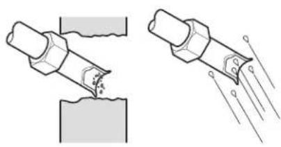
natural_image
Two technical illustrations showing a pipe joint being welded with a surface, and a close-up of the weld joint with visible wear and impact lines (no text or symbols)
natural_image
Technical line drawing of a mechanical component with cross-sectional view (no text or symbols)
text_image
Technical diagram showing a mechanical clamp mechanism with cross-sectional view and dimension annotations

natural_image
Line drawing of a hand giving a thumbs-up gesture to a cylindrical object (no text or symbols)
text_image
Diagram illustrating battery charging process with four battery cells and a hand holding a bulb, showing rotation and disassembly steps.

text_image
Technical diagram showing two cross-sectional views of a mechanical or fluid system with labeled components and directional arrows.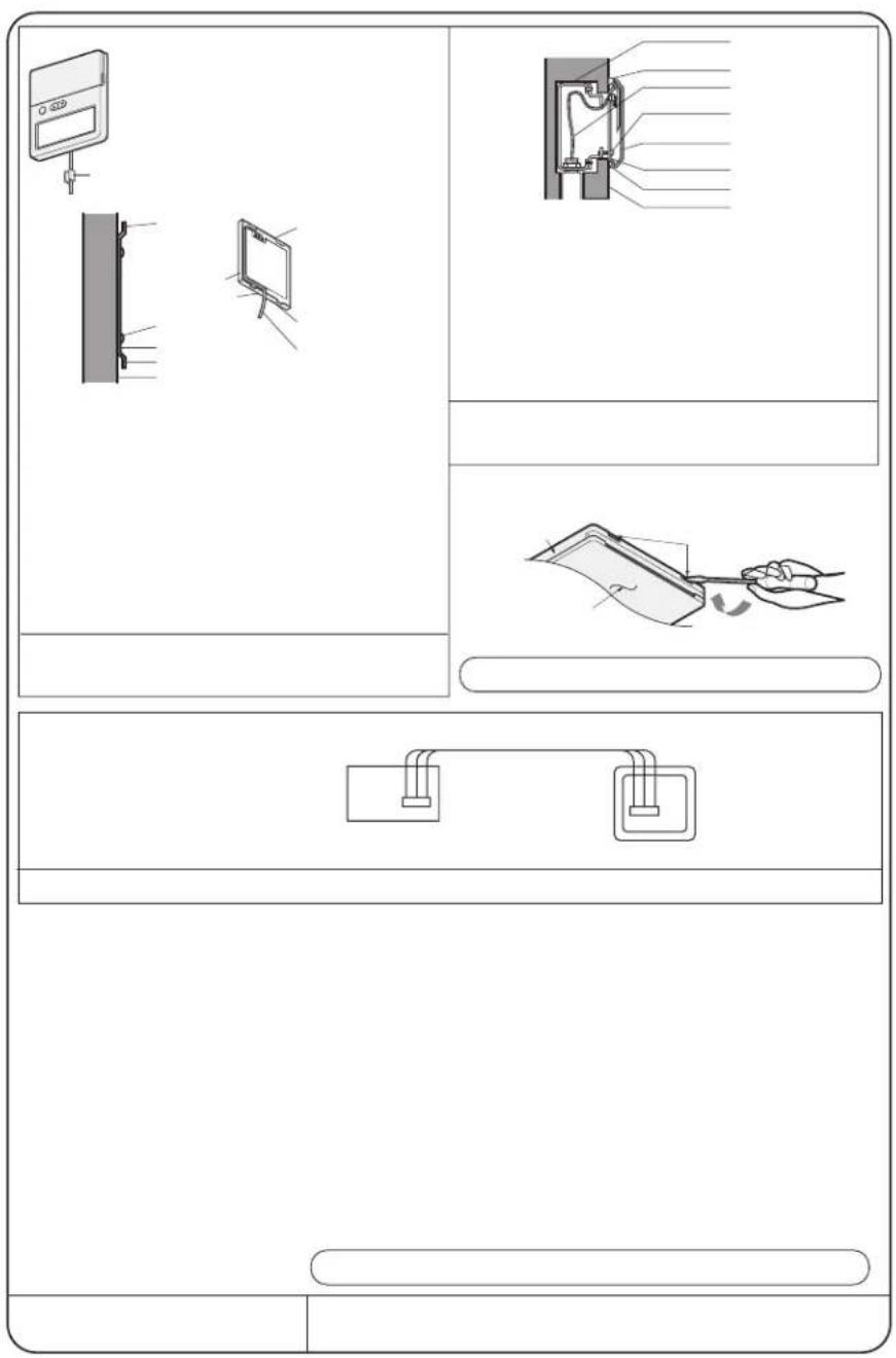
text_image
Diagram showing three panels of a device with labeled components and assembly steps, including front, top, and side views.
text_image
A270mm B 2×SP C 2×SP C 2×2mm B 24mm A 70mm B 70mm C 20mm A 10mmA EX Exchmal Pressure (mmA) SP = Exchmal Pressure A 10mmA U-tarp A B C
text_image
Indoor unit 5 Mtrs U-Tarp Outdoor unit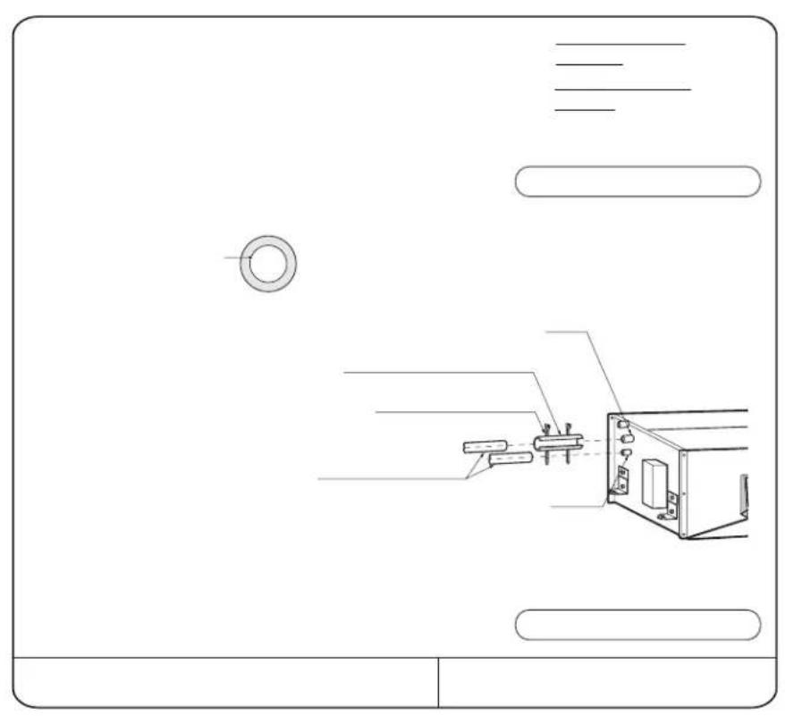
natural_image
Technical line drawing of a mechanical assembly with no visible text or symbols
natural_image
Diagram of a mechanical joint or weld with a tool inserted, showing force direction and displacement (no text or symbols)
text_image
Technical diagram showing various pipe and support structures with annotations like 'N/W' and cross symbols, likely from an engineering or mechanical drawing.
text_image
Technical diagram showing a structural support system with labeled components and directional arrows indicating movement or force.
natural_image
Simple line drawing of a hand holding a tool above a 3D coordinate plane (no text or symbols)
text_image
Technical diagram showing a device with labeled components and a close-up view of its internal structure.
natural_image
Technical drawing of a mechanical component with top and side views (no text or symbols)
text_image
Blank grid paper with a diagonal line on the right edge, likely for text entry or layout reference.
text_image
Remote Controller Air Inade vents Air outlet vents Air filter Air filter

natural_image
Technical line drawing of a mechanical fan or evaporator unit with dimension lines (no text or symbols)
text_image
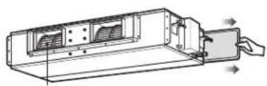
Air intake vents Air outlet vents Side Pirear Piping

text_image
Drainage hole H - F G D C E B A
natural_image
Grid pattern with a diagonal line and a triangle at the bottom-right corner (no text or symbols)
natural_image
Technical line drawing of a mechanical device with internal components and directional arrows (no text or symbols)


natural_image
Technical line drawing of a rectangular electronic device with internal components and mounting bracket (no text or symbols)
natural_image
Two horizontal gray bars of different shades, one elongated and one solid with a dark center (no text or symbols)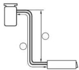
natural_image
Pure diagram of a pipe with two ends and circular indicators, no text or symbols present
text_image
Sunrout More than 100m More than 50m More than 30m Fence or obstacles More than 50m
natural_image
Technical diagram showing two mechanical or structural components with dimension lines and alignment indicators (no text or symbols)
flowchart
graph TD
    A[" "] --> B[" "]
    B --> C["▼"]
    C --> D[" "]
    D --> E[" "]
    E --> F[" "]
    F --> G[" "]
    G --> H[" "]
    H --> I["▼"]
flowchart
graph TD
    A[" "] --> B["↓"]
    C[" "] --> D["↓"]

natural_image
Blank gray rectangular image with no visible text, symbols, or features____ ____ ____
The image contains no text or characters. It is a graphical element (a blank rectangle) and does not contain any legible content. Therefore, the correct OCR output is an empty string.

text_image
Scanned document page with barcode and user interface elements, featuring a stylized graphic design.91
Lifes Good
57