Volta VU12NC - Çelës HAGER - Manual falas për përdoruesin
Gjeni manualet e pajisjes falas Volta VU12NC HAGER në format PDF.

Pyetjet e përdoruesve rreth Volta VU12NC HAGER
0 pyetje rreth kësaj pajisjeje. Përgjigjuni atyre që njihni ose bëni tuajin.
Bëni një pyetje të re rreth kësaj pajisjeje
Shkarko udhëzimet për tuajin Çelës në format PDF falas! Gjeni manualin tuaj Volta VU12NC - HAGER dhe merrni pajisjen tuaj elektronike sërish në duar. Në këtë faqe janë publikuar të gjitha dokumentet e nevojshme për përdorimin e pajisjes suaj. Volta VU12NC e markës HAGER.
MANUAL I PËRDORUESIT Volta VU12NC HAGER
:hager
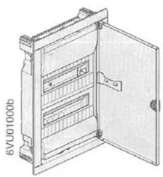
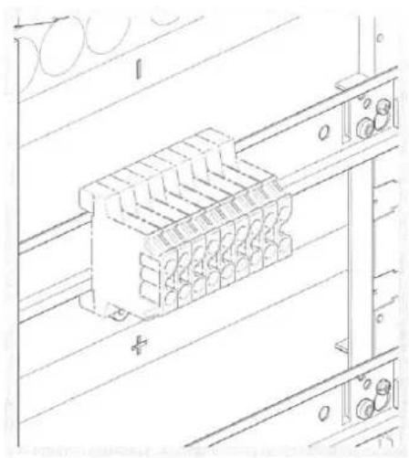
natural_image
Technical line drawing of an open electrical enclosure with internal compartments (no text or symbols)Volta
DE Montageanleitung
FR Notice d'instructions
GB Mounting instructions
NL Montage instructie
DK Monteringsvejledning
FI Asennusohje
NO Montasjeanvisning
SE Monterings instruktioner
IT Istruzioni di montaggio
ES Instrucciones de montaje
PT Instruções de montagem
© CZ Montážní návod
BA Uputstvo za montažu
HR Upute za montažu
HU Szerelési útmutató
LT Montavimo instrukcija
LV Montāžas instrukcija
PL Instrukcja montażowa
RO Instructiuni de montare
SK Návod na montáž
RU Инструкция по монтажу
BG Инструкции за монтаж
GR Οδηγίες χώνευσης
SI Navodilo za montažo
EE Paigaldusjuhised
IS Leiðbeiningar
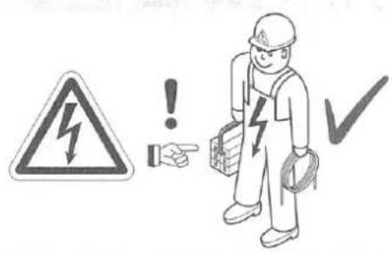
text_image
Safety warning sign with lightning bolt symbol and warning symbols for hazard, hand pointing to a person holding a device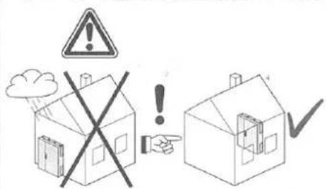
text_image
Safety warning illustration showing a house with a cross symbol crossed out, indicating no need for using a device.
text_image
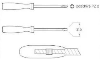
poz/drive PZ 2 2.5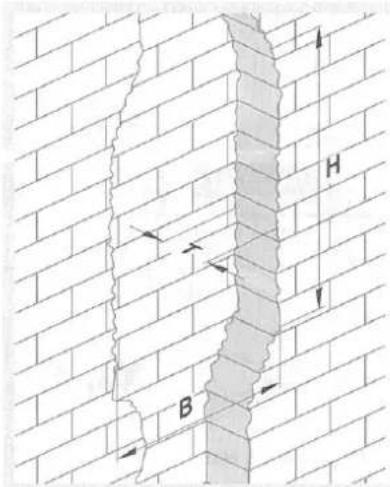
text_image
Diagram showing brick wall with labeled points B and H, indicating structural elements or layers.| B | H | T | |
| VU12... | 335 mm | 340 mm | 90 mm |
| VU24... | 335 mm | 490 mm | 90 mm |
| VU36... | 335 mm | 615 mm | 90 mm |
| VU48... | 335 mm | 740 mm | 90 mm |
natural_image
Technical line drawing of an electrical enclosure with mounting brackets and internal components, shown in two views (no text or symbols present)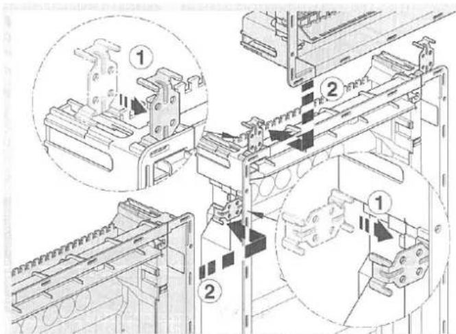
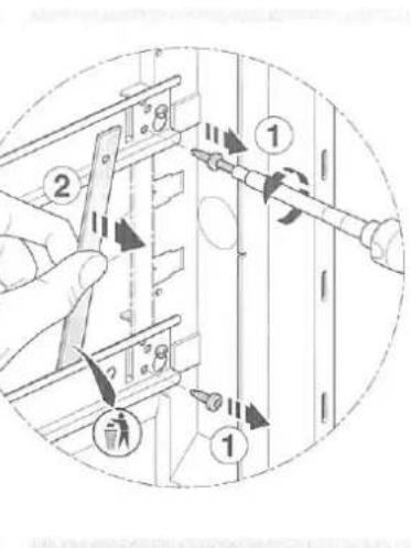
text_image
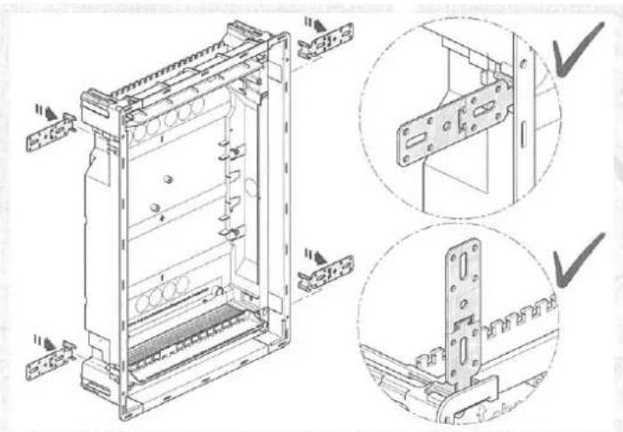
Technical diagram showing mechanical assembly steps with numbered annotations indicating component placement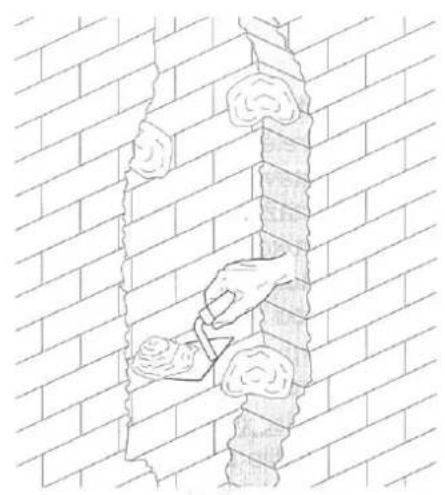
natural_image
Line drawing of a brick wall with a hand using a tool to cut or mark a crack (no text or symbols)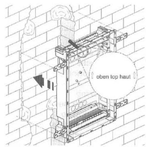
text_image
oben top haut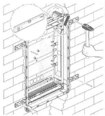
natural_image
Technical illustration of an electrical enclosure with hand using hammer to install components, mounted on a brick wall (no text or symbols)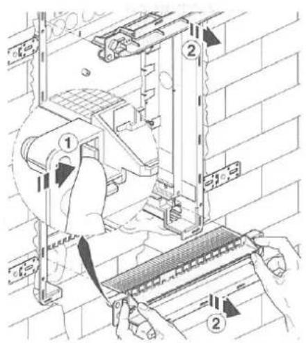
text_image
Technical diagram showing installation steps with numbered annotations indicating components like '①' and '②'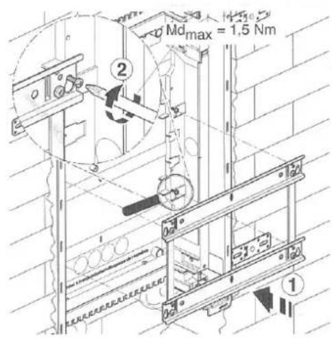
text_image
Mdmax = 1.5 Nm ②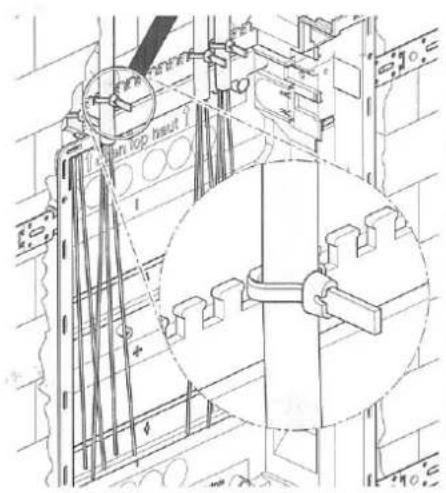
text_image
Top top heat
natural_image
Technical line drawing of a mechanical assembly with inset showing a gear and gear mechanism (no text or symbols)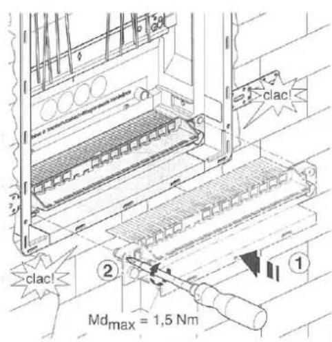
text_image
① ② ③ ④ Mdmax = 1,5 Nm clac clac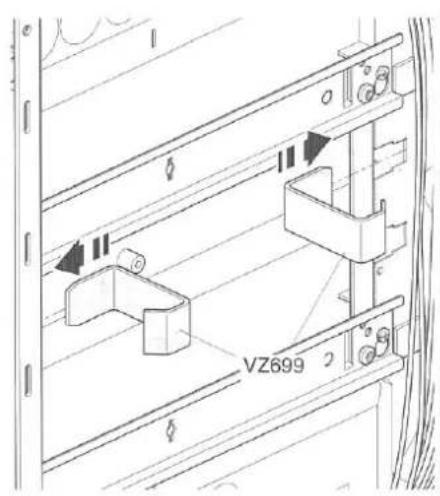
text_image
VZ699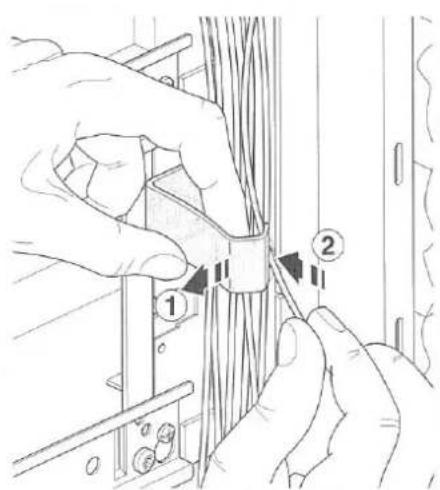
text_image
Technical diagram showing hands installing or adjusting cable components with numbered parts labeled 1 and 2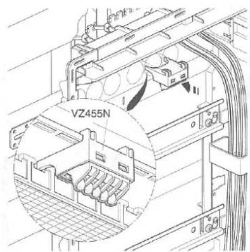
text_image
VZ455N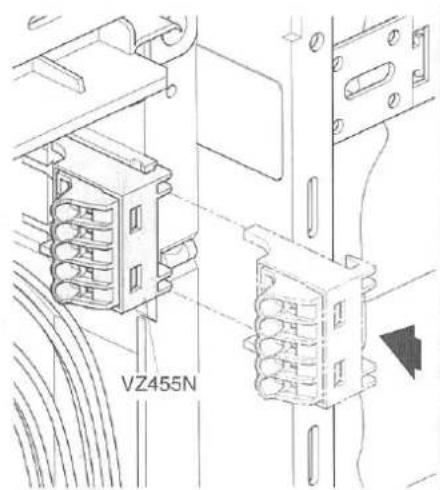
text_image
VZ455N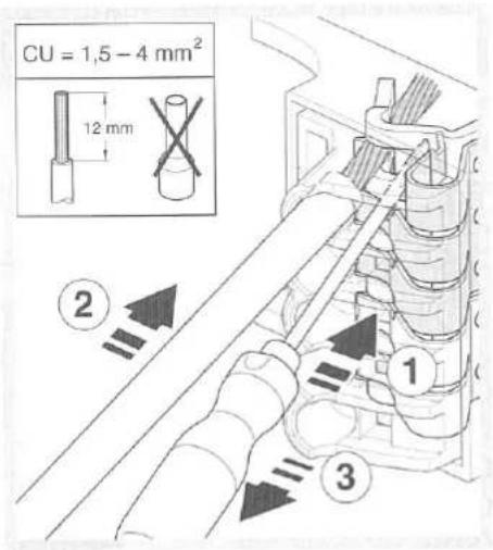
text_image
CU = 1,5 - 4 mm² 12 mm ② ① ③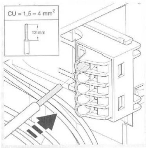
text_image
CU = 1,5 - 4 mm² 12 mm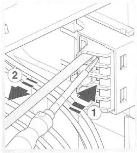
text_image
Technical diagram showing cable routing between two connected devices with numbered annotations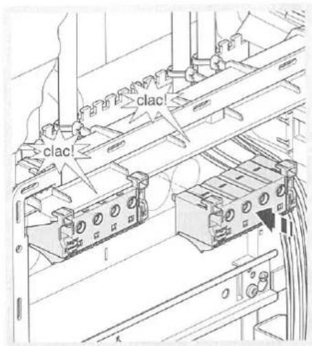
text_image
clac! clac!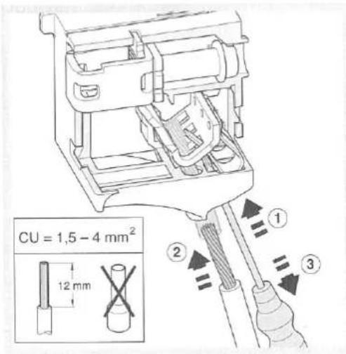
text_image
CU = 1,5 - 4 mm² 12 mm ① ② ③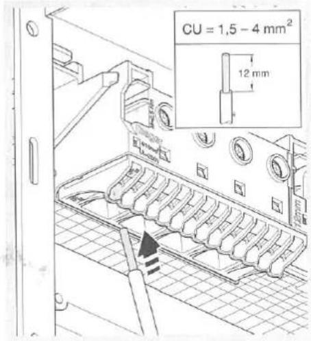
text_image
CU = 1,5 - 4 mm² 12 mm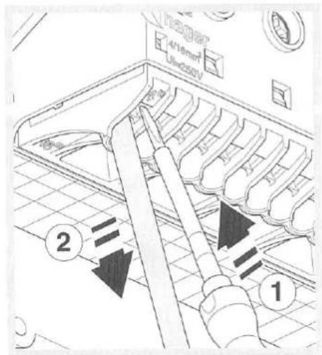
text_image
4/16min² Us=250V ① ②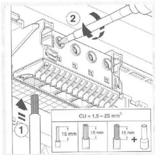
text_image
① ② CU = 1,5 - 25 mm² 15 mm 15 mm 15 mm +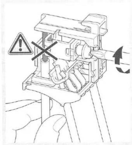
natural_image
Diagram of a mechanical device with a hand holding a tool, showing internal components and a warning symbol (no text or labels present)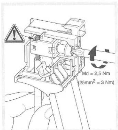
text_image
Md = 2,5 Nm (25mm² = 3 Nm)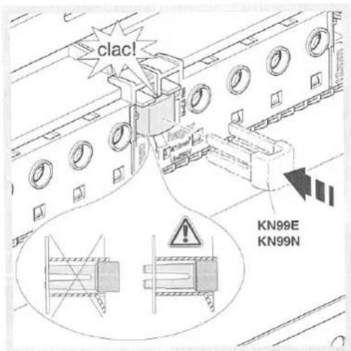
text_image
clac! KN99E KN99N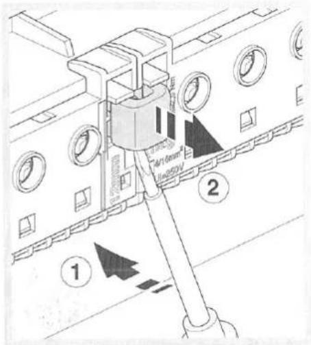
text_image
Technical diagram showing a mechanical assembly with labeled parts and directional arrows indicating motion or force directions.
natural_image
Technical line drawing of a mechanical assembly with no visible text or symbols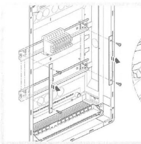
text_image
Technical diagram of an electrical cabinet with labeled components and wiring connections