6100E - Tekalna steza SportsArt - Brezplačna navodila za uporabo
Brezplačno poiščite navodila za napravo 6100E SportsArt v formatu PDF.

Vprašanja uporabnikov o 6100E SportsArt
0 vprašanje o tej napravi. Odgovorite na tiste, ki jih poznate, ali zastavite svoje.
Zastavite novo vprašanje o tej napravi
Prenesite navodila za vaš Tekalna steza v formatu PDF brezplačno! Poiščite svoja navodila 6100E - SportsArt in vzemite svojo elektronsko napravo nazaj v roke. Na tej strani so objavljeni vsi dokumenti, potrebni za uporabo vaše naprave. 6100E znamke SportsArt.
NAVODILA ZA UPORABO 6100E SportsArt
SPORTS ART COMMERCIAL GRADE 6100E MOTORIZED TREADMILL
SAFETY GUIDELINES:
Please read and follow these safety guidelines:
. Read this owner's manual and follow the instructions
. Assemble and operate the treadmill on a solid, level surface.
. Never allow children on or near the treadmill.
. Check the treadmill before every use. Make sure all parts are assembled, and all nuts and bolts are tightened. DO NOT use the treadmill if the unit is disassembled in any way.
. Keep your hands away from moving parts.
. Wear proper workout clothing: DO NOT wear loose clothing. DO NOT wear shoes with leather soles or high heels. Tie all long hair back.
. Don't rock the unit from side to side, and use care when mounting and dismounting the unit.
. DO NOT use any accessories that aren't specifically recommended by the manufacture these might cause injuries or cause the unit to fail.
. Work within your recommended exercise level DO NOT work to exhaustion.
. If you feel any pain or abnormal symptoms, STOP YOUR WORKOUT and consult your physician immediately.
Warning—To reduce the risk of burns, fire, electric shock, or injury to persons:
. A treadmill should never be left unattended when plugged in. Unplug from outlet when not in use, and before putting on or taking off parts.
. Close supervision is necessary when this treadmill is used by, on, or near children, invalids, or disabled persons.
. Use this treadmill only for its intended use as described in this manual.
. Never operate this treadmill if it has a damaged cord or plug, if it is not working properly, if it has been dropped or damaged, or dropped into water. Return the treadmill to a service center for examination and repair.
. Do not carry this treadmill by supply cord or use cord as a handle.
. Keep the cord away from heated surfaces.
. Never operate the treadmill with the air openings blocked. Keep the air openings free of lint, hair, and the like.
. Never drop or insert any object into any opening.
. Do not use outdoors.
. Do not operate where aerosol (spray) products are being used or where oxygen is being a dministered.
. To disconnect, turn all controls to the off position, than remove plug from outlet.
. Connect this treadmill to a properly grounded outlet only.
CAUTION:
Before beginning any exercise program, you should consult with your doctor. It is recommended that you undergo a complete physical examination.
TABLE OF CONTENTS
- SAFETY GUIDELINES.... 1
- INTRODUCTION.... 3
- ASSEMBLING YOUR TREADMILL.... 4
Installation Requirements.... 4
List of parts.... 4
Step by step instructions.... 5
Floor level adjustment.... 7
- MODES OF OPERATION.... 8
MANUAL 8
What each of the categories means.... 8 - RUNNING ON THE TREADMILL.... 9
- MAINTAINING YOUR TREADMILL.... 9
Cleaning the treadmill.... 9
Adjusting the running belt.... 10
- TROUBLE SHOOTING.... 13
ERR message.... 13
Fuse failure for electronics package and motor.... 14
Fuse failure for incline system.... 15
Fuse failure for Drive Board.... 15
INTRODUCTION
Congratulations on purchasing one of the finest pieces of commercial exercise equipment on the market today, the 6100E. Constructed of high quality materials and designed for years of troublefree usage. We hope the 6100E will be an integral part of your fitness regimen.
Before using your 6100E Treadmill, we recommend that you familiarize yourself with this Owner's Manual. Whether you are a first time user of exercise equipment or a seasoned "pro", understanding the correct use of the equipment will enhance your ability to achieve your exercise goals safely and successfully.
ASSEMBLING YOUR TREADMILL
Installation Requirements
Read this owner's manual and follow the instruction contained herein.
Caution: Two persons are recommended to assemble the treadmill. To avoid back strain, and to ensure safety to the unit and yourself, we suggest you avoid lifting the running bed assembly from box. Instead, lay the treadmill down, drop the sides of the box and slide the treadmill from the container rather than lifting it.
IMPORTANT: The packing for this treadmill was designed to protect it during shipment, please store the original packaging in a safe place in case you need to ship the unit in the future.
List Of Parts
Before assembling your treadmill, make sure that you have all following items:
- Eight 5/16" x 3/4" bolts - lift post
- Eight 5/16" washers - lift post
- Eight 5/16" nylon washers - lift post
- One water bottle holder
- Two 1/4"x1/2" screws - water bottle holder
- One screw driver
- One hex Allen wrench
- One hex Allen wrench with handle
-
One combination wrench
-
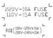
Three f uses
a. 15A (100V/120V use) or 10A (200V/240V use) - Electronics and motor
b. 4A - Incline system
c. 3 A (100V/120V use) or 2A (200V/240V use) - Drive board
Step By Step Instructions
When you remove the treadmill from its box, first check to make sure all of the parts are present. Then, read through the assembly instructions before you begin.
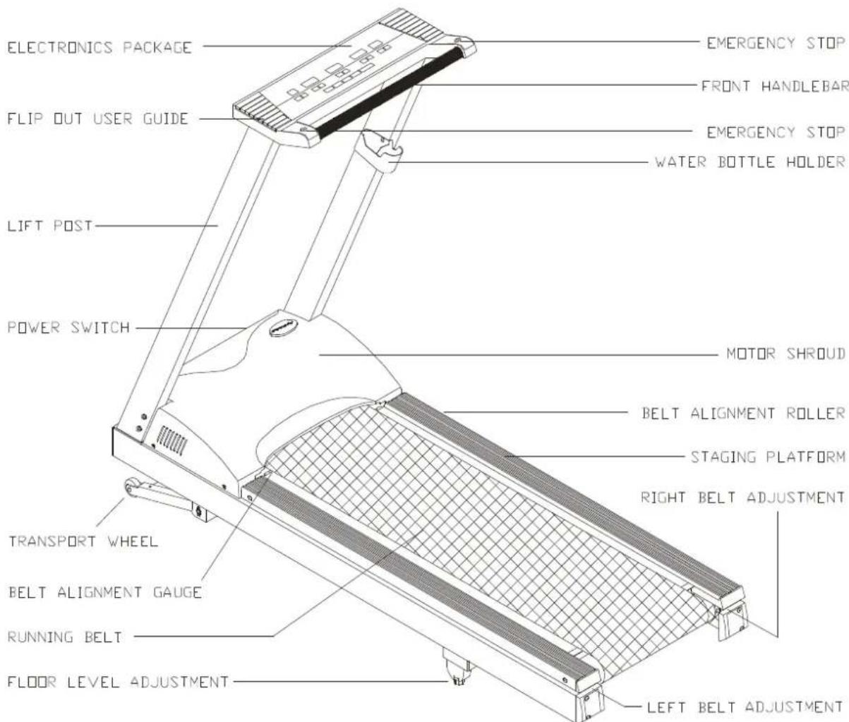
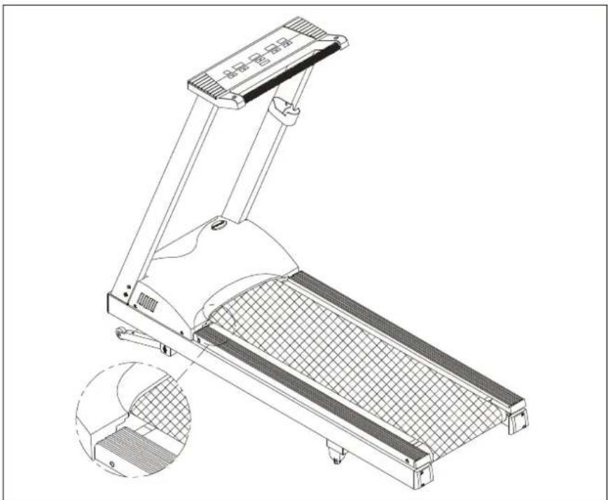
- Lay the treadmill on its side. Make sure the running belt is in position in the tracks of the Belt Alignment Guides on the underside of the machine. (see Fig. 1).
natural_image
Technical line drawing of a mechanical device with internal components and a magnified inset showing a textured surface detail (no text or symbols)FIG.1
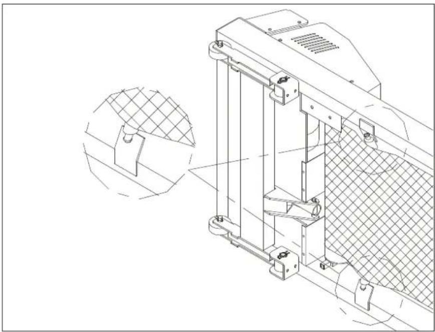
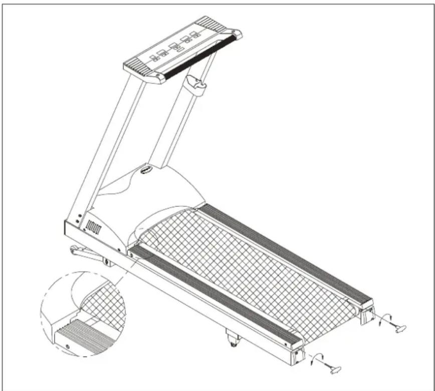
- Insert the two front posts into their respective sockets and secure with four bolts and washers provided on each side.(see Fig. 2).
natural_image
Technical line drawing of a treadmill with adjustable arms and control knobs (no text or symbols)FIG.2
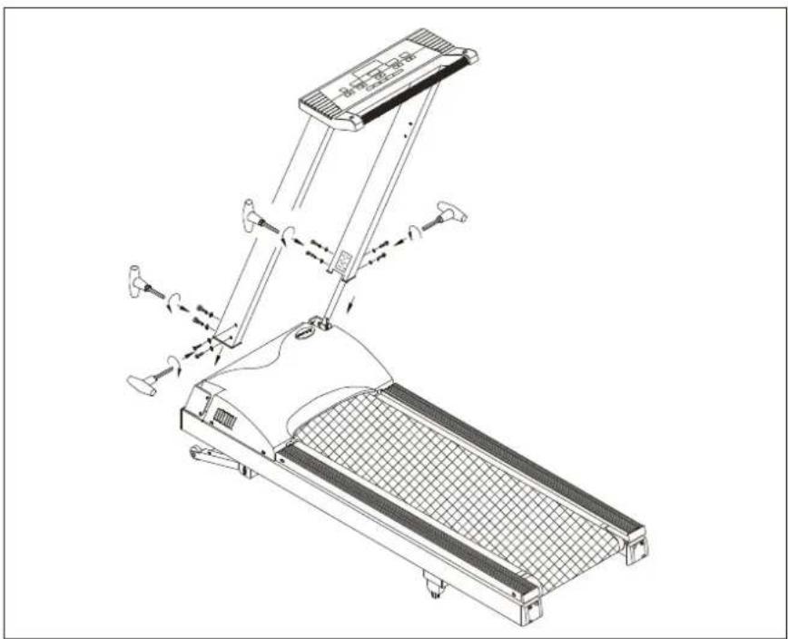
- Assemble the water bottle/personal stereo holder to the right front post using the screws provided.(see Fig. 3).
natural_image
Line drawing of a treadmill with mesh grille and front-mounted top (no text or symbols)FIG.3
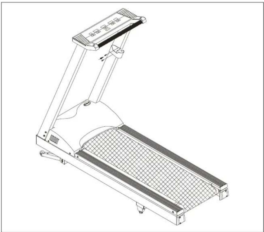
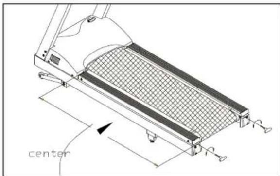
IMPORTANT: Before using the treadmill, the left edge of the running belt must be completely in the green portion of the BELT ALIGNMENT GAUGE, located on the left side of the motor shroud. Please refer to the "Maintaining your treadmill" section "Adjusting the running belt" for further information.(see Fig. 4).
natural_image
Technical line drawing of a treadmill with mesh grille and side-mounted frame (no text or symbols)FIG.4
Floor Level Adjustment
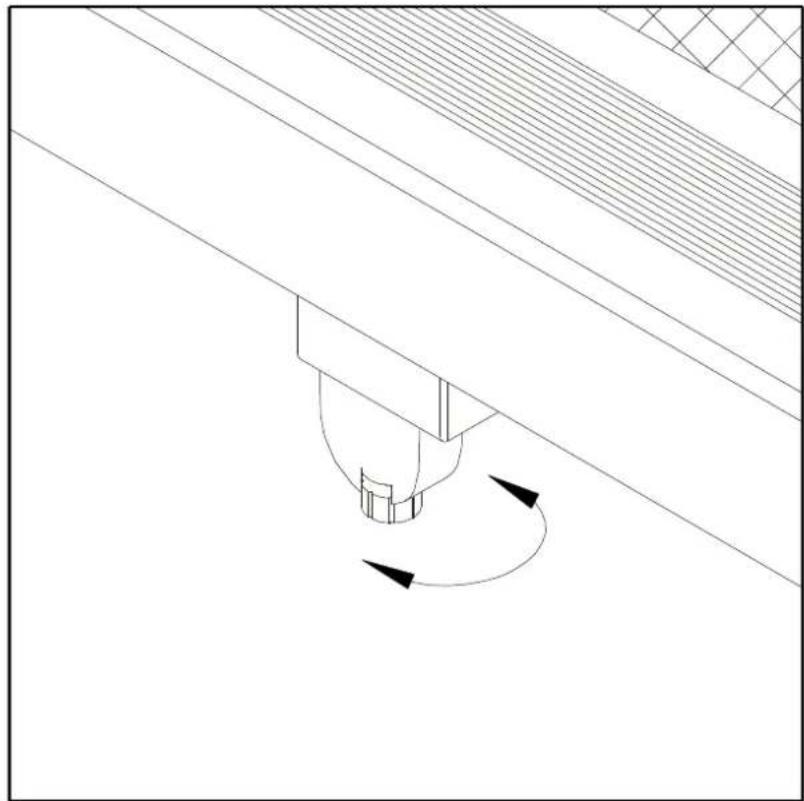
If the treadmill is unsteady on your floor, turn the floor level adjustment on the rear feet of the treadmill. Raise or lower the floor level adjustment to steady your treadmill (see Fig. 5).
natural_image
Technical line drawing of a mechanical component with rotational motion arrows (no text or symbols)FIG.5
MODES OF OPERATION
CAUTION: DO NOT STAND ON THE BELT WHEN STARTING. Straddle the belt with your feet on the right and left staging platforms.
MANUAL:
As soon as you turn on the machine, it will go straight into the "MANUAL" mode. The speed LED will flash, press the SPEED key to start the treadmill, and the INCLINE keys to raise or lower the treadmill.
What each of the categories means:
SPEED ▲▼: Use the speed ▲▼ key to adjust your desired speed. The speed range for the treadmill is from 0.1-12 mph (0.2-20 kph). Press the speed ▲key to increase the speed and press the speed ▼ key to decrease the speed.
INCLINE ▲▼: Use the INCLINE ▲▼ key to raise or lower the treadmill. The incline range for the treadmill is from 0%-15%.
TIME: The range available in TIME mode is 00:00-99:00 minutes. Use the TIME ▲▼ to set the desired time. The electronics package will BEEP for 10 seconds when your desired time is reached, then will start to count up if you workout continues. Each press of the key change the time by 1 minute.
DISTANCE: The distance of the treadmill will register goes from 0-99.99 miles or 0-99.00 kilometers. Use the ▲▼ to set the desired distance. Each press of the button change the distance by 0.1 miles or 0.1km.
CAL: This readout gives you the amount of calories burned per minute. The range of calories is from 0-999.9CAL.
RUNNING ON THE TREADMILL
Now, you have become familiar with your treadmill's operation and are ready to exercise:
- Plug the treadmill into a standard outlet. Turn on the power switch located on the front of the machine.
- Straddle the belt with your feet on the right and left staging platforms.
- Select your course and follow the scrolled messages. You may also PRESS the SPEED keys to begin.
- Press speed (key until you reach 1.5-2.0 mph/2.5-3.5 kph or a comfortable walking speed, keep both hands on the handrails, and walk for a few minutes to get comfortable with your treadmill.
- After you are walking in an easy, relaxed, and steady fashion, now release your grip on the handrails, and let your arms swing freely and naturally.
- When you feel comfortable walking, you may wish to jog. Hold the handrail with one hand, use the other hand to increase the speed for jogging.
- Remember to hold the handrail when using the control panel on the electronics package, or to catch your balance when slowing down or stopping, and for dismounting.
- When you have finished your workout, just press the STOP key located on both sides of the handrail. Remember to cool down before you end.
MAINTAINING YOUR TREADMILL
Your treadmill relies on low friction for peak performance. The treadmill's low friction operation is dependent on keeping the unit as clean as possible. See "Cleaning the Treadmill" for further information.
Proper belt alignment is also important for proper operation of the treadmill. See "Adjusting the Running Belt" for further information.
Cleaning The Treadmill
CAUTION: Turn off the unit and disconnect the AC cord before cleaning.
Regular cleaning is recommended to keep your treadmill running at peak performance.
Before your workout, use a dry cloth to clean the landing platform, exposed slider bed, and under the belt as far as you can easily reach. This removes any dirt or dust which might enter the slider area and compromise the unit's running efficiency.
To clean the plastic parts, use a mild detergent and make sure the unit is completely dry before operating. On the running surface, use a soft nylon scrub brush. Do not use water to clean the belt or running surface, or to clean the electronics package. Should water, for some reason, get on the electronics package, immediately blow dry.
It is recommended that you keep all liquids away from the unit during operation.
Spillage of liquids onto or into the machine will void the warranty.
Adjusting the Running Belt
Your 6100E comes with a belt alignment gauge located on the left side of the motor cover. The edge of the running belt should be in the middle of the green portion of the gauge. If the belt edge is in the green area, the belt does not need adjusting. If the left edge is in the red portion, the belt needs adjusting immediately (see Fig. 6).
natural_image
Technical line drawing of a treadmill with mesh panel and side-mounted legs (no text or symbols)FIG.6
The belt is properly aligned at the factory. However, during shipping and handling or by use on an uneven surface, the belt may move off center. Therefore, it is important that you check the belt's alignment before using the treadmill.
The correct alignment of the running belt is critical for the smooth operation of the treadmill.
CAUTION: DO NOT ALLOW ANYONE TO WALK ON RUNNING BELT DURING THIS PROCEDURE.
Failure to realign the belt could result in tearing or fraying of the belt, which is not covered in the warranty. Please follow the adjustment procedure listed below:
- Turn on the power switch located on the front of machine.
- Press the SPEED ▲ key to increase the speed until the speed registers 2.0mph / 3.2kph on the digital display.
- While the unit is running at 2 mph/3.2kph, determine where the belt is in relation to the belt alignment gauge.
- Should your belt be in the wrong color range, follow the steps below to return the belt to the "safety zone":
- If the belt is in the left red zone: Stop the machine, turn the left belt adjustment bolt located at the rear of the treadmill clockwise 1/4 turn at a time, using the hex Allen wrench. Then turn the right belt adjustment bolt counterclockwise 1/4 turn. Let the treadmill run 30 seconds, then check the position of the belt in the color gauge. If the belt still has not returned to the green safety zone, repeat with another 1/4 turn until the belt has returned to the middle of the green area. Do not turn adjusting bolt more than 1/4 turn at a time.
If the belt is on the edge of the green color, please adjust it so it is in the middle of the green color. You may turn the adjustment bolt less than 1/4 turn at a time. - Conversely, if the belt is in the right red zone, turn the right belt adjustment bolt clockwise 1/4 turn, then turn the left adjustment bolt counterclockwise 1/4 turn. Then let the treadmill run at least 30 seconds, check the position of the belt in the color gauge. If it still has not returned to the green safety zone, repeat with another 1/4 turn until the belt has return to the middle of the green area. Do not turn adjusting bolt more than 1/4 turn at a time.
- When the belt is back in the green "safety zone", you can continue your regular use of the treadmill. Slowly increase the speed of the unit to 5.5 MPH (9 KPH), and let it run for at least 45 seconds.
Periodically monitor the position of the belt to ensure peak performance:
When you are using the treadmill, if you feel a pause in the belt with each foot plant the belt is too loose. Stop the machine, check the belt tension, left the running belt off the deck in the middle (see 7 & 7-1). There should be about 15m/m (5/8") or 3-5 kgs of "give" in the belt. If there is too much (see Fig. 7-2), then adjust both rear roller bolts clockwise 1/2 turn at a time (see Fig. 7-3).
natural_image
Technical line drawing of a treadmill with a grid-patterned panel and directional arrows indicating movement (no text or symbols)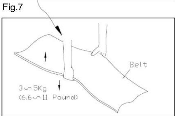
Fig.7-1
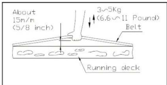
Fig.7-2
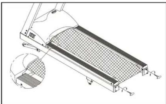
natural_image
Technical line drawing of a treadmill with mesh panel and side-mounted legs (no text or symbols)Fig.7-3
CAUTION: To avoid injury, special care must be taken when adjusting the running belt. Turn off the treadmill while adjusting or working near the rear rollers. Remove any loose clothing or shoe laces and tie back your hair. Be very careful to keep your fingers or any other objects clear of the belt and rollers. The treadmill is designed to carry specific weights at specific speeds. The treadmill will not stop immediately if any object becomes caught in the belt or rollers.
Over tightening of the belt causes damage and premature failure of the precision ings in the front and rear rollers.
TROUBLE S HOOTING
ERR Message
ERR 1- The optical switch mounted on the motor is not receiving the signal reflected from the tachometer wheel. Please contact your dealer.
ERR 3- The user is running faster than the belt. Please turn off the machine and try normal use again.
ERR 6- The unit's incline system may be damaged, please contact your dealer for more information.
ERR 7- The electronics package is receiving the signal reflected from the VR incorrectly, which means the terminal wires are disconnected, or the VR is damaged. Please contact your dealer for more information.
ERR 8- The electronics package CPU communication is disabled: please contact your dealer for more information.
ERR 9- When the treadmill has been run 30,000 Miles (48,000 Km), the display will show ERR 9. We recommend the replacement of certain critical parts at 30,000 miles (48,000 Km) to ensure peak performance, please contact your dealer for more information.
To temporarily disable the ERR 9 message, you may press the DISTANCE key.
ERR 10- Treadmill speed doesn't match the setting. Contact your local dealer for assistance.
Fuse Failure For Electronics Package And Motor
If nothing is displayed on the electronics package, please check the POWER switch located on the front of the treadmill. If it is unlit, then the fuse is damaged and must be replaced.
CAUTION: MAKE SURE THE TREADMILL PLUG IS REMOVED FROM OUTLET BEFORE REPLACING THE FUSE.
There are two fuse holders located at the front of the treadmill frame, the right 4 amp fuse holder is for the INCLINE SYSTEM, and the left fuse holder 15 amp/100-120 volts (or 10 amp/220-240 volts) is for the Electronics Package and Motor (see Fig.8), please make sure to check your standard voltage prior to fuse replacement.
To remove the fuse for the electronics package and motor, push on the fuse holder and then turn the holder counterclockwise and the fuse holder with fuse will protrude. Remove the damaged fuse and insert a new fuse, pushing the fuse and holder in, then turning clockwise to secure the fuse holder (see Fig. 8-1\~8-3).
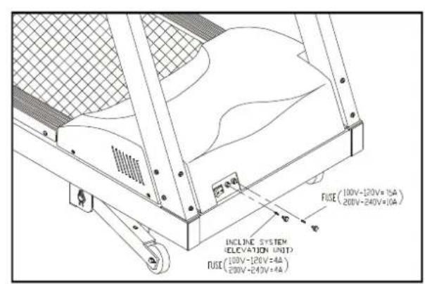
Fig.8
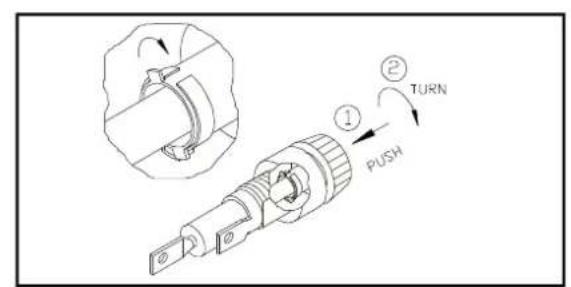
Fig.8-1
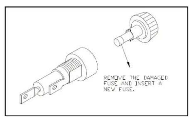
Fig.8-2
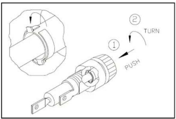
Fig.8-3
If the unit's electronics package or motor refuses to respond after changing the fuse, please contact your dealer for more information.
Fuse Failure For Incline System
Should the incline system refuse to respond, but there is power to the electronics package and it remains operable, please replace the incline system fuse.
The 4amp fuse is for the Incline system. To remove the incline system fuse, push on the fuse holder and then turn the holder counterclockwise and the fuse holder with fuse will protrude. Remove the damaged fuse and insert a new fuse, pushing the fuse and holder in, then turning clockwise to secure the fuse holder (see Fig.8-1\~8-3).
If the incline system refuses to respond after changing the fuse, please contact your dealer for more information.
Fuse Failure For Drive Board
NOTE: If you are not a technician or do not have expert knowledge of this machine. Please do not attempt to replace it.
If there is nothing displays on the electronics package, and the POWER SWITCH located on the front of the treadmill if lit, then the fuse is damaged on the drive board and must be replaced.
The fuse holder 3 A (100V/120V) or 2A (200V/240V) for the drive board is located on the frame at the front of the treadmill (see Fig. 9).
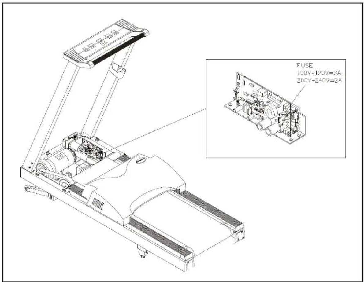
Fig.9
Wiring Schematic:
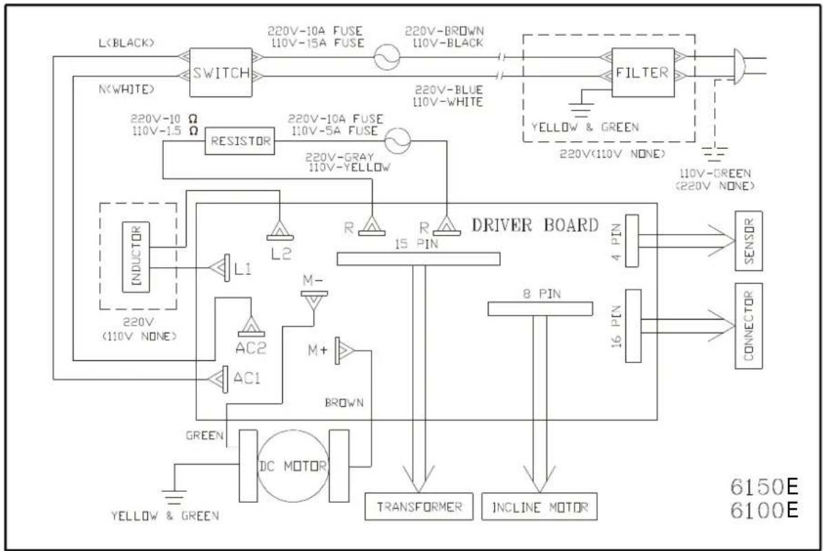
flowchart
graph TD
    A["L<BLACK>"] --> B["SWITCH"]
    B --> C["220V-10A FUSE 110V-15A FUSE"]
    C --> D["220V-BROWN 110V-BLACK"]
    D --> E["FILTER"]
    E --> F["220V(110V NONE)"]
    E --> G["110V-GREEN (220V NONE)"]
    G --> H["SENSOR"]
    G --> I["CONNECTOR"]
    H --> J["8 PIN"]
    I --> K["4 PIN"]
    J --> L["TRANSFORMER"]
    K --> M["INCLINE MOTOR"]
    N["N(WHITE)"] --> O["RESISTOR"]
    O --> P["220V-10A FUSE 110V-5A FUSE"]
    P --> Q["220V-BROWN 110V-BLACK"]
    Q --> R["FILTER"]
    R --> S["220V(110V NONE)"]
    T["INDUCTOR"] --> U["L1"]
    U --> V["AC2"]
    V --> W["AC1"]
    W --> X["BROWN"]
    X --> Y["8 PIN"]
    Y --> Z["INCLINE MOTOR"]
    AA["DC MOTOR"] --> AB["GREEN"]
    AB --> AC["YELLOW & GREEN"]
    AD["R"] --> AE["M+"]
    AE --> AF["M-"]
    AG["R"] --> AH["M+"]
    AI["R"] --> AJ["M-"]
    AK["R"] --> AL["M+"]
    AM["R"] --> AN["M-"]
    AO["R"] --> AP["M+"]
    AQ["R"] --> AR["M-"]
    AS["L2"] --> AT["L1"]
    AT --> AU["AC2"]
    AU --> AV["AC1"]
    AW["7-PIN"] --> AX["8 PIN"]
    AY["220V-1.5 Ω"] --> AZ["RESISTOR"]
    BA["220V-GREEN 110V-NONE"] --> BB["7-PIN"]
    BC["6150E"] --> BD["6100E"]
Your Authorized SPORTS ART Distributor
15A15