ID-HCEN-9136 - Punct de acces Ventev - Manual de utilizare gratuit
Găsiți gratuit manualul dispozitivului ID-HCEN-9136 Ventev în format PDF.

Întrebările utilizatorilor despre ID-HCEN-9136 Ventev
0 întrebare despre acest aparat. Răspundeți la cele pe care le cunoașteți sau puneți-vă propria.
Pune o întrebare nouă despre acest aparat
Descărcați instrucțiunile pentru Punct de acces în format PDF gratuit! Găsiți manualul dvs. ID-HCEN-9136 - Ventev și luați din nou în mână dispozitivul dvs. electronic. Pe această pagină sunt publicate toate documentele necesare pentru utilizarea dispozitivului dvs. ID-HCEN-9136 mărcii Ventev.
MANUAL DE UTILIZARE ID-HCEN-9136 Ventev
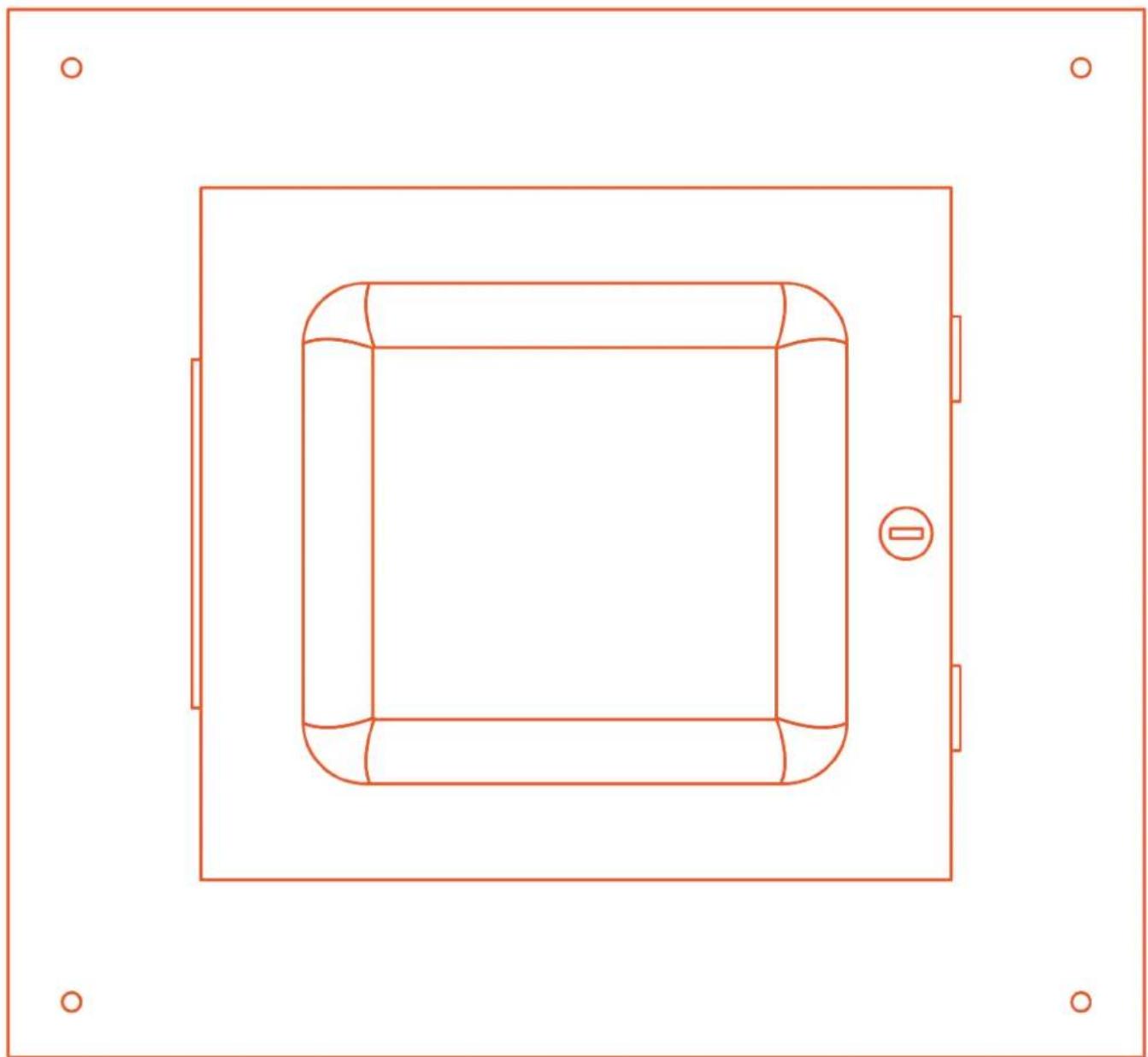
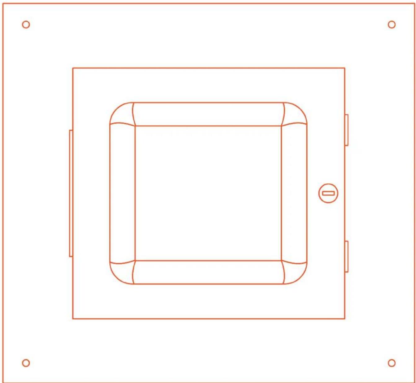
Installation Manual
Hard Lid Ceiling Enclosure
natural_image
Top-down schematic of a vehicle inside a rectangular frame, showing structural components and no text or symbols.Ventev Hard Lid Ceiling Enclosure Instructions
Step 1
The enclosure comes with four 14 in. holes spaced on 16 in. centers as shown. It is recommended to center the holes with studs in the ceiling. Access Point (AP) not included.
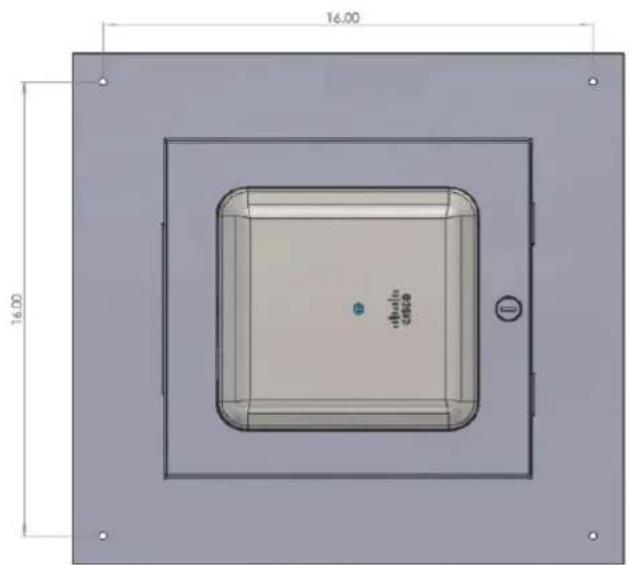
Step 2
A 14 x 14 in. square hole is required to be cut into the ceiling to allow the enclosure to be recessed into the ceiling.
natural_image
Simple 3D rectangular frame with a small circular hole at the center, no text or symbols present.Enclosure Base
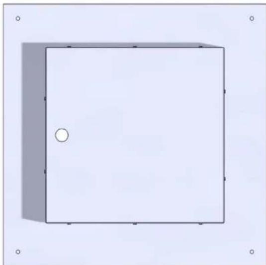
Step 3
Slide the enclosure into the hole and secure to the ceiling with the appropriate hardware for the type of installation you are encountering. For studs, use #12 x 1.5 in. wood screws. If mounting to other materials use the correct wall anchors to support the enclosure plus the weight of the AP of approximately 5 lbs.
Cisco Access Point Instructions
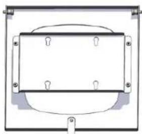
Step 4
Remove the door from the ceiling tile assembly by pulling the heads of the two spring pins that act as the door hinge.
natural_image
Pure electrical circuit lines without any symbolsStep 5
Remove the four screws or nuts that hold the AP Mounting Bracket to the door.
Step 6
Place AP in door from the front side. Slide the cross bar onto the AP mounting feet from the back side.
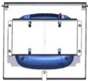
natural_image
Pure diagram of a blue cylindrical component with mounting holes and a central vertical line, no text or symbols present.Step 7
Attach the cross bar to the door with four screws or nuts.
Step 8
Run the RJ 45 cable into the large hole in the tray of the enclosure and secure the wire with the romex connector.
Step 9
Attach door assembly to installed base in the ceiling and attach RJ45 cable to AP.
Step 10
Close the door and lock.
Aruba Access Point Instructions (500 Series and Newer)
Step 4
Remove the door from the ceiling tile assembly by pulling the heads of the two spring pins that act as the door hinge.
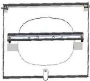
natural_image
Simple line drawing of a rectangular frame with an oval shape inside, no text or symbols present.Step 5
Remove the two screws that hold the AP cross bar to the door stand offs.
Step 6
Remove the black factory mount from the AP and retain the two screws.
Step 7
Place AP in door from the front side. Screw the cross bar onto the AP from the back side using the screws that were removed from the AP.
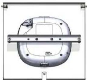
natural_image
Technical line drawing of a mechanical component with mounting holes and a central horizontal bar (no text or symbols)Step 8
Attach the cross bar to the door with the two screws from step five.
Step 9
Run the RJ 45 cable into the large hole in the tray of the enclosure and secure the wire with the romex connector.
Step 10
Attach door assembly to installed base in the ceiling and attach RJ45 cable to AP.
Step 11
Close the door and lock.
ventev
11126 McCormick Road,
Hunt Valley, MD 21031
800-851-4965
sales@ventev.com
ventevinfra.com