NU-AK310 - Niekategoryzowane SHARP - Bezpłatna instrukcja obsługi
Znajdź bezpłatnie instrukcję urządzenia NU-AK310 SHARP w formacie PDF.

| Typ produktu | Mikrofalówka |
| Marka | Sharp |
| Model | NU-AK310 |
| Wymiary (szer. x gł. x wys.) | 48 x 35 x 26 cm |
| Pojemność | 20 litrów |
| Masa | 11,5 kg |
| Zasilanie | 230 V ~ 50 Hz |
| Moc mikrofal | 800 W |
| Funkcje | Automatyczne rozmrażanie, podgrzewanie, gotowanie, programy dla potraw |
| Typ wyświetlacza | LED |
| Sterowanie | Przyciski dotykowe i pokrętło |
| Blokada przed dziećmi | Tak |
| Sygnał dźwiękowy | Tak |
| Materiał obudowy | Stal nierdzewna |
| Drzwi | Szkło hartowane, otwierane przyciskiem |
| Czyszczenie | Przecierać wilgotną ściereczką, unikać środków ściernych |
| Części zamienne | Talerz obrotowy, bezpiecznik, żarówka dostępne w serwisie |
| Gwarancja | 2 lata |
| Certyfikaty | CE, RoHS |
| Informacje ogólne | Produkt przeznaczony do użytku domowego, nie komercyjnego |
Często zadawane pytania - NU-AK310 SHARP
Pytania użytkowników dotyczące NU-AK310 SHARP
0 pytanie dotyczące tego urządzenia. Odpowiedz na te, które znasz, lub zadaj własne.
Zadaj nowe pytanie dotyczące tego urządzenia
Pobierz instrukcję dla swojego Niekategoryzowane w formacie PDF za darmo! Znajdź swoją instrukcję NU-AK310 - SHARP i weź swoje urządzenie elektroniczne z powrotem w ręce. Na tej stronie opublikowane są wszystkie dokumenty niezbędne do korzystania z urządzenia. NU-AK310 marki SHARP.
INSTRUKCJA OBSŁUGI NU-AK310 SHARP
PLEASE READ THIS MANUAL CAREFULLY BEFORE INSTALLING OR USING THE MODULES. PLEASE PASS ALONG THE ATTACHED USER MANUAL TO YOUR CUSTOMER.
INSTALLATION MANUAL - Crystalline Photovoltaic Module -
MODEL NU-AK300, NU-AK310, NU-AK300B
# IMPORTANT SAFETY INSTRUCTIONS p.1
# GENERAL INSTRUCTIONS p.1 \~ p.3
# INSTALLATION MANUAL -PHOTOVOLTAIC MODULES- p.4
# ELECTRICAL OUTPUT AND THERMAL CHARACTERISTICS p.4
IMPORTANT SAFETY INSTRUCTIONS
This manual contains important safety instructions for the PV module that must be followed during the maintenance of PV modules.
To reduce the risk of electric shock, do not perform any servicing unless you are qualified to do so.
- The installation must be performed by a certified installer /servicer to ensure system integrity and safety.
-
The installation is only allowed after referring and understanding of this INSTALLATION MANUAL. If you don't have your personal copy, please contact your installer or local Sharp office listed in Sharp Solar web site : URL : http://www.sharp-world.com/solar
-
Do not pull the PV cables.
-
Do not touch any surface of module.
-
Do not place/drop objects onto the PV modules.
-
Do not disassemble or attempt to repair the PV module by yourself.
-
Do not drop the PV module.
-
Do not damage, pull, bend, or place heavy material on cables.
-
Upon completion of any service or repairs, ask the installer/servicer to perform routine checks to determine that the PV modules are in safe and proper operating condition.
-
When replacement parts are required, be sure the installer/servicer uses parts specified by the manufacturer with same characteristics as the original parts. Unauthorized substitutions may result in fire, electric shock, or other hazard.
- Consult your local building and safety department for required permits and applicable regulations.
- In regions with snow, the module can sustain a snow load of up to 50cm (when the module is mounted in the portrait orientation / short frame side facing down) or 100cm (when the module is mounted in the landscape orientation / long frame side facing down).
- As a result of sliding snow, the mechanical load increases when the number of module rows in the matrix of a PV installation increases. When mounting the module in the portrait orientation for more than 3 rows, the accumulated snow load may cause the lower edge of the module frame to deform. Take necessary measures (e.g. snow stopper) to avoid possible damage.
- Periodically remove any overhanging snow and/or ice from the module framework as it may cause deformation of the module frame.
CAUTION: HIGH VOLTAGE
To reduce the risk of electric shock, do not touch.

GENERAL INSTRUCTIONS
1. INTRODUCTION
This Installation Manual contains essential information for the electrical and mechanical installation that you must know before installing SHARP PV modules. This also contains safety information you need to be familiar with. All the information described in this manual are the intellectual property of SHARP and based on the technologies and experiences that have been acquired and accumulated in the long history of SHARP. This document does not constitute a guaranty, expressed or implied. SHARP does not assume responsibility and expressly disclaims liability for loss, damage, or expense arising out of or in any way connected with installation, operation, use or maintenance of the PV modules. No responsibility is assumed by SHARP for any infringement of patents or other rights of third parties that may result from use of PV module. SHARP reserves the right to make changes to the product, specifications or installation manual without prior notice.
- COMPONENTS

text_image
Connector Electrical Cable Junction box Superstrate Glass Frame Solar Photovoltaic Cell3. GENERAL INFORMATION (INCLUDING WARNING AND SAFETY)
The installation of PV modules requires a great degree of skill and should only be performed by a qualified licensed professional, including licensed contractors and licensed electricians. Please be aware that there is a serious risk of various types of injury occurring during the installation including the risk of electric shock. All SHARP PV modules are equipped with a permanently attached junction box that will accept variety of wiring applications or with a special cable assembly for ease of installation, and they do not require special assembly.
GENERAL WARNING
- PV modules are heavy. Handle with care.
- Before you attempt to install, wire, operate and maintain the PV module, please make sure that you completely understand the information described in this installation manual.
- Contact with electrically active parts of a PV module such as terminals can result in burns, sparks and lethal shock whether the PV modules are connected or not.
- PV modules produce electricity when the sufficient sunlight or other sources illuminate the module surface. When the modules are connected in series, voltage is cumulative. When the modules are connected in parallel, current is cumulative. As a result, a large-scale PV system can
produce high voltage and current which could present an increased hazard and may cause serious injury or death.
- Do not connect the PV modules directly to the loads such as motors since the variation of the output power depending on the solar irradiation causes damage for the connected motor.
1: In the case of a brushless motor, the lock function becomes active and the hall IC is most likely to be damaged.
-
In the case of a brush type motor, the coil is most likely to be damaged.
-
In case of snow build-up, snow would slide easier on the smooth surface of the module than other parts of the roof. Snow may suddenly slide, fall off the roof and hit nearby objects/lanes. Take preventive measures (e.g. snow stopper) when there is possible risk such case would cause an injury or a damage.
GENERAL SAFETY
-
Consult local codes and other applicable laws concerning required permits on regulations for installation and inspection requirements.
-
Before installing a PV module, contact appropriate authorities to determine permit, installation and inspection requirements that should be followed.
-
Install PV modules and ground frames in accordance with applicable rules and regulations.
-
PV modules should be installed and maintained by qualified personnel. Only installarservice personnel should have access to the PV module installation site.
-
No matter where the PV modules are installed, either roof mounted construction or any other type of structures above the ground; appropriate safety practices should be followed and required safely equipment should be used in order to avoid possible safety hazards. Note that the installation of some PV modules on roofs may require the addition of flooring, depending on local building fire codes.
-
In the case that the PV modules are non-integral type, the module is to be mounted over a fire resistant roof.
-
Use PV modules with the same cell size within series.
-
Follow all safety precautions of other components that are used in the system.
-
In order to avoid a risk of injury or electrical shock, do not allow anyone to approach the PV module if the person has little knowledge on PV module or on the measures that should be taken when PV modules are damaged.
-
Do not shade portions of the PV module surface from the
reverse current flow. The current may easily flow in a reverse direction.
- Keep modules away from children.
HANDLING SAFETY
-
Do not cause an excessive load on the surface of PV module or twist the frame. The glass surface can easily break.
-
Do not stand or step on the PV module. The surface glass of PV module is slippery.
-
Do not hit or put excessive load on the glass or back sheet. The PV call is very thin and can be easily broken.
-
Do not scratch or hit at the back sheet. The back sheet is vulnerable.
-
Do not damage the junction box or do not pull the cables. The junction box can crack and break.
-
Never touch junction box or the end of output cables with bare hands when the PV module is imadiated. Cover the surface of PV module with cloth or other suitable sufficiently opaque material to isolate the PV module from incident light and wear rubber gloves when handling the wires to avoid electric shock.
-
Do not scratch the output cable or bend it with force. The insulation of output cable can break and may result in electricity leakage or shock.
-
Do not pull the output cable excessively. The output cable may unplug and cause electricity leakage or shock.
-
Do not drill holes in the frame, it may compromise the frame strength and cause corrosion.
-
Do not scratch the insulation coating of the frame (except for grounding connection). It may cause corrosion of the frame or compromise the framework strength.
-
Do not touch the PV module with bare hands. The frame of PV module has sharp edges and may cause injury.
-
Do not drop PV module or allow objects to fall down on the PV module.
-
Do not concentrate sunlight artificially on the PV module.
- Do not hold the PV module on one side. The frame ma
band or twist. Hold the PV module at opposite sides.
- Do not touch the anti-reflective coated glass since finger prints and/or stains can be easily left on the glass surface.
INSTALLATION SAFETY
-
Always wear protective head gear, insulating gloves and safety shoes (with rubber soles). Do not wear metallic jewellery to prevent electric shock during installation.
-
Keep the PV module packed in the carton until installation.
problems such as animal biting, electricity leakage in puddle.
- Take proper measures for preventing the laminate (consisted of resin, cells, glass, back sheet, etc.) from dropping out of the frame in case the glass is broken.
- Cables shall be located so that they will not be exposed to direct sunlight after installation to prevent degradation of cables.
- If batteries are used with modules, follow safety precautions of the battery manufacturer.
- In case of extreme snow build-up, the weight of the snow may cause the module's frame to deform. Take appropriate preventive measures to minimize any possible resulting damage.
4. SITE SELECTION
In most applications, the PV modules should be installed in a location where there is no shading throughout the year. In the Northern Hemisphere, the PV modules should typically face south, and in the Southern Hemisphere, the PV modules should typically face north.
Please make sure that there are no obstructions in the surroundings of the site of installation. TAKE PROPER STEPS in order to maintain reliability and safety, in case the PV modules are used in areas such as: Heavy snow areas / Extremely cold areas / Strong wind areas / Installations over, or near, water / Areas where installations are prone to salt water damage/corrosive gas environment/ Small islands or desert areas.
The results of the ammonia test and the salt-mist-corrosion test on the modules, carried out under such strict test conditions, should be disclosed for reference purposes only. The decision on whether the modules are suitable and compatible for each installation field will depend on the user's judgement and responsibility.
5. TILT ANGLE
The tilt angle is the measurement between the PV module and a horizontal ground surface. The PV module generates the maximum output power when it faces the sun directly. 5 degrees or more is recommended for the tilt angle of the PV module for the maintenance. (See 9. Maintenance)
For the standalone systems with a battery where the PV modules are attached to a permanent structure, the tilt angle of the PV modules should be determined to optimize the performance when the sunlight is the scarcest. In general, if the electric power generation is adequate when the sunlight is the scarcest, then the angle chosen should be adequate during the rest of the year. For grid-connected installations where the PV modules are attached to a permanent structure, it is recommended to tilt the PV module at the angle equal to the latitude of the installation site so that the power generation from the PV module will be optimum throughout the year.
6. WIRING
To ensure proper system operation and to maintain your guaranty, observe the correct cable connection polarity (Figures 1 & 2) when connecting the modules to a battery or to other modules. If not connected correctly, the bypass diode could be destroyed.
PV modules can be wired in series to increase voltage. Connect wires from the positive terminal of one module to the negative terminal of the next module. Figure 1 shows modules connected in series.
Connect PV modules in parallel to increase current. Connect wires from the positive terminal of one module to the positive terminal on the next module. Figure 2 shows modules connected in parallel.


7. GROUNDING
The frame grounding must consider the local requirement and regulation at the installation site. When grounding is required, please refer to below example connection (Figure 3). Please be careful in arranging the system ground so that the removal of one module from the circuit will not interrupt the grounding of any other modules.
The modules should be grounded to the same electrical point as described below.
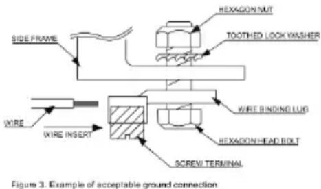
text_image
SIDE FRAME WIRE WIRE INSERT HEXAGON NUT TOOTHED LOCK WASHER WIRE BINDING LUG HEXAGON HEAD BOLT SCREW TERMINAL Figure 3. Example of acceptable ground connectionYou can use a hole with the appropriate symbol for equipotential bonding on the side frame for either a bolt, nut and washer grounding the module to the frame, a ground lug fastened by bolt or screw, or appropriate screw (hardware not provided). An example of acceptable ground connection using a bolt, nut and washer retaining a ground lug is shown in figure 3. In a connection of this type, the hardware (such as a toothed locked washer / star washer) must score the frame surface to make positive electrical contact with the frame. The ground wire must be considered within the local requirement of local and regulation at the site of installation.
8. MOUNTING
Please make sure that all the information described in the installation manual is still valid and proper for your installation. The mounting method has been verified by SHARP and NOT CERTIFIED by a third party organization.
The approved way to mount Sharp PV modules to a support structure is described in this INSTALLATION MANUAL. Although Sharp does not specify or warrant frame clips or clamps, using frame clips (not provided) or clamps (not provided) is possible when they are designed for PV modules and with minimum dimensions on the sides of the module in accordance with the instructions and drawings provided. If using frame clips or clamps, the modules should be fixed rigidly and there shall be no damage to the modules by deforming mounting structure against design load.
The Sharp module guaranty may be void if customer-selected frame clips are improper or inadequate for module properties (including strength or material) or installation. Note that if metal clips are used, there must be a path to ground from the clips, (for instance, using star washers in the clip hardware set). Please review the descriptions and drawings carefully; not mounting the modules according to one of these methods may void your guaranty. These mounting methods are designed to allow module loading of 2400Pa. The module has passed a snow load test of 5400Pa according to IEC61215. Support structures that PV modules are mounted on should be rigid. Sharp PV modules are designed to ensure optimal electrical performance under the condition that they are mounted on rigid support structures. Deformation of support structure may damage PV module with its electric performance. When mounting the module on structure, ensure that no corner has a displacement of more than 2mm per every 1000mm of the diagonal.
9. MAINTENANCE
The modules are designed for long life and require very little maintenance. If the angle of the PV module is 5 degrees or more, normal rainfall is sufficient to keep the module glass surface clean under most weather conditions. If dirt build-up becomes excessive, clean the glass surface preferably with water only, or with wet soft sponge or cloth in case to remove stubborn dirt. If cleaning the back of the module is required, take utmost care not to damage the back side materials. In order to ensure the operation of the system, check the connection of wiring and the state of the jacket of wires occasionally.
INSTALLATION MANUAL -PHOTOVOLTAIC MODULES-
1. INSTALLATION
The mounting method has been verified by SHARP and NOT CERTIFIED by a third party organization. Please review the descriptions and drawings carefully; not mounting the modules according to one of these methods may void your guaranty. These mounting methods are designed to allow module loading of 2400Pa.
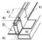
Mounting Using Clips: Clamping on Longer Frame (Figure2)
The modules can be mounted using clips (damps) designed for solar nodules as defined in the following Figures. Note that the mounting dips should meet the required dimensions as defined in the Figure1. Note that the CLIP CENTER POSITION(e) is important as specified in the Figure2. The module must be supported on the array system and should over lap the array roll by at least 10mm. The array rails (see point list image, row or vertical row) must support the bottom of the frames and must be continuous piece (no breaks in the rail).
2. ELECTRICAL INSTALLATION INSTRUCTION
CABLE requirement
Conductor size: 4.0mm².
Cable type: XLPE cable (H1Z2Z2-K cable)
MaximumDC voltage: 1.5kV
Rating temperature: -40°C to +90°C.
Figure1. Clips (Clamps) equipment
1) Clip A alloy 3mm Min thickness
2) Catch length (50mm Min.)
3) Covering depth (Three Min on the face)
4) Supporting depth (10mm Min.)
5) Fennie
(applicable to all from a section)
6) Army rail
(applicable to parallel or crossed mounting)
Module configuration (Recommend)
- Maximum series configuration: please refer to Table-1 (This value is calculated under the condition of Voc at -40 °C.)
# Maximum parallel configuration: (Parallel connection of each string shall be conducted with following two options. Any other parallel connections are prohibited.)
a) Case of using the diodes; 1 diode per maximum 2 parallel strings (Connect a diode or more in series for every string or every 2 parallel strings for protection of module from reverse current over load.)
b) Case of using the fuses: 1 fuse per every string (Connect a fuse for every single string for protection of module from reverse current over load.)
CONNECTOR requirement
The module shall be mated to the same connectors:
Type: MC4
Brand: Staubli Electrical Connectors
3. WARNING
Keep all MODULES and electrical CONNECTORS clean & dry before installation.
4. Disposal
Disposie photovoltaic modules properly. For information about the proper disposal, contact your local recycling site
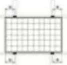
207 nm √6×330mm
e: spantons module corner to dip corner
Figure2: Clamping on longer frame
ELECTRICAL OUTPUT AND THERMAL CHARACTERISTICS