CWDM/X - Rozdzielacz Omnitron Systems - Bezpłatna instrukcja obsługi
Znajdź bezpłatnie instrukcję urządzenia CWDM/X Omnitron Systems w formacie PDF.

Pytania użytkowników dotyczące CWDM/X Omnitron Systems
0 pytanie dotyczące tego urządzenia. Odpowiedz na te, które znasz, lub zadaj własne.
Zadaj nowe pytanie dotyczące tego urządzenia
Pobierz instrukcję dla swojego Rozdzielacz w formacie PDF za darmo! Znajdź swoją instrukcję CWDM/X - Omnitron Systems i weź swoje urządzenie elektroniczne z powrotem w ręce. Na tej stronie opublikowane są wszystkie dokumenty niezbędne do korzystania z urządzenia. CWDM/X marki Omnitron Systems.
INSTRUKCJA OBSŁUGI CWDM/X Omnitron Systems
Design Considerations
iConverter CWDM/X modules are passive devices that require no external power. Attenuation (signal loss) of less than 2.7dB will be realized through each port on the module (see the CWDM/X Data Sheet for exact loss specification for each model). Detailed calculations should be performed for each fiber optic link in the network to ensure the proper optical devices are specified with sufficient transmitter power.
When calculating optical loss, ensure that the total loss, plus a safety factor (typically 3dB) does not exceed the optical power budget. The optical power budget is the difference between the transmitter optical output power and the receiver's optical sensitivity. The transmitter optical output power and receiver optical sensitivity values can be obtained from the manufacturers of the respective equipment. Please consult the iConverter data sheets for CWDM/X signal loss specifications.
For more information, access Omnitron's documentation download web page to view all relevant documents:
http://www.omnitron-systems.com/downloads.php
Warranty
WARNING
The operating description in this Instruction Manual is for use by qualified personnel only. To avoid electrical shock, do not perform any servicing of this unit other than that contained in the operating instructions, unless you are qualified and certified to do so by Omnitron Systems Technology.
Warranty
This product is warranted to the original purchaser against defects in material and workmanship for a period of ONE YEAR from the date of shipment. You may register your product on the Internet at http://www.omniltron-systems.com. During the warranty period, Omniltron will, at its option, repair or replace a product which is proven to be defective.
For warranty service, the product must be sent to an Omnitron designated facility, at Buyer's expense. Omnitron will pay the shipping charge to return the product to Buyer's designated US address using Omnitron's standard shipping method.
Limitation of Warranty
The foregoing warranty shall not apply to defects resulting from improper or inadequate use and/or maintenance of the equipment by Buyer, Buyer-supplied equipment, Buyer-supplied interfacing, unauthorized modifications or tampering with equipment (including removal of equipment cover by personnel not specifically authorized and certified by Omnifron), or misuse, or operating outside the environmental specification of the product (including but not limited to voltage, ambient temperature, radiation, unusual dust, etc.), or improper site preparation or maintenance.
No other warranty is expressed or implied. Omnitron specifically disclaims the implied warranties of merchantability and fitness for any particular purpose.
Exclusive Remedies
The remedies provided herein are the Buyer's sole and exclusive remedies. Omnitron shall not be liable for any direct, indirect, special, incidental, or consequential damages, whether based on contract, tort, or any legal theory.
040-08860-001D 9/13
Omnitron Systems Technology * 38 Tesla * Irvine, CA 92618 949.250.6510 tel * 949.250.6514 fax * www.omnitron-systems.com
OSt Omnitron Systems
iConverter CWDM/X 4 and 8 Channel MUX/DEMUX USER MANUAL
Product Overview
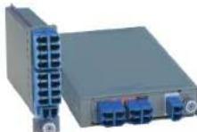
Omnitron's iConverter CWDM/X Coarse Wave Division Multiplexing (CWDM) Multiplexer/Demultiplexer (MUX/DEMUX) modules support ITU-T G.694.2 wavelengths between 1270nm to 1610nm in 20nm increments.
The iConverter CWDM/X modules are available in 4 supporting a variety of wavelengths and optional port 6 channels are supported by combining two 8-Channel Band Splitter. For more information, access Omnitron's want documents:
http://www.omnitron-systems.com/cwdm_multiplexers.php
Port Definitions
4-Channel 8-Channel
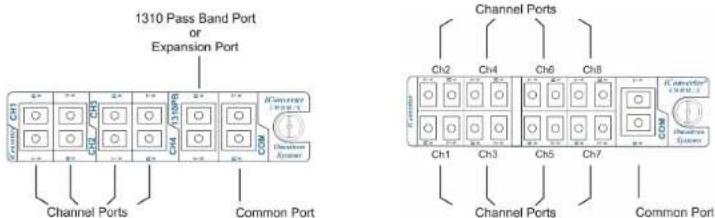
Figure 1: Port Locations for 4-Channel and 8-Channel CWDM/X Module
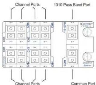
Figure 2: Port Locations for 8-Channel Double-Wide CWDM/X Module
Channel Port
The Channel Ports transmit and receive signals on specific CWDM wavelengths. The Channel Ports are multiplexed onto and demultiplexed from the Common Port.
Common Port
The Common Port (COM) transmits and receives the aggregated wavelengths connected to the Channel, Expansion and 1310 Pass Band Ports.
1310 Pass Band Port
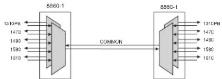
The 1310 Pass Band Port (1310PB) allows a legacy 1310nm signal to pass through the CWDM/X module on a reserved band (1260nm to 1360nm). The port can be used to combine an existing legacy 1310nm network with up to 8 CWDM channels, allowing the CWDM channels in the range of 1470nm to 1610nm to be overlaid on the same fiber pair as the existing 1310nm network. Figure 3 illustrates two CWDM/X modules with the 1310 Pass Band Port option.
flowchart
graph LR
    A["8860-1"] -->|COMMON| B["8860-1"]
    A -->|1310PB| A
    A -->|1470| A
    A -->|1490| A
    A -->|1590| A
    A -->|1610| A
    B -->|1310PB| B
    B -->|1470| B
    B -->|1490| B
    B -->|1590| B
    B -->|1610| B
Figure 3: 4-Channel MUX/DEMUX
Expansion Port
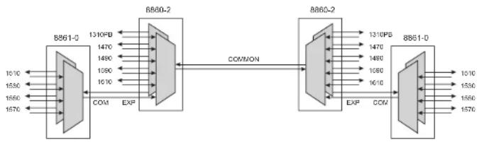
The Expansion Port (EXP) enables the cascading of two CWDM/X modules as shown in Figure 4. On models 8860-2 and 8860-3, the Expansion Port can also be used as a 1550nm Pass Band Port to transport legacy 1550nm single-mode traffic as long as the spectral width of the 1550nm legacy network is between 1510 and 1570nm.
flowchart
graph LR
    A["8861-0"] -->|COM| B["8860-2"]
    B -->|COMMON| C["8860-2"]
    C -->|EXP| D["8861-0"]
    D -->|COM| C
    A -->|EXP| B
    B -->|COMMON| C
    C -->|EXP| D
    D -->|COM| C
    A -->|1310PB| B
    B -->|1470| C
    C -->|1310PB| D
    A -->|1470| B
    B -->|1490| C
    C -->|1490| D
    A -->|1590| B
    B -->|1610| C
    C -->|1610| D
    A -->|1610| D
    B -->|1610| D
    C -->|1610| D
    A -->|1550| B
    B -->|1550| C
    C -->|1550| D
    A -->|1570| B
    B -->|1570| C
    C -->|1570| D
Figure 4: Two Cascaded 4-Channel MUX/DEMUX
Only the 4-Channel CWDM/X module is available with an optional Expansion Port.
8-Channel CWDM/X MUXes require the use of the Band Splitter (8865-0) to multiplex 16 channels over the Common Port.
Installation
- Carefully slide the module into an open slot in an iConverter chassis. Align the module with the installation guides and ensure that the module is firmly seated against the backplane. Secure the module by fastening the front panel thumbscrew(s) (push in and turn clockwise to tighten) to the chassis front. The CWDM/X module requires no external power, however, if management is required, the module must be installed in an iConverter powered chassis with a Network Management Module (NMM2 Model 8000N-0) or a media converter with integrated management (such as the iConverter 10/100M2)*.
- Connect a single-mode, dual fiber duplex LC cable between the Channel Port of the CWDM/X module and the attached device. It is important to ensure that the wavelength of the CWDM/X matches the wavelength of the attached device. Connect all Channel Ports in this manner. Ensure that the transmit (Tx) is attached to the receive side of the device at the other end, and the receive (Rx) is attached to the transmit side.
- Connect a single-mode, dual fiber duplex LC cable between the Common Ports on the CWDM/X modules (this connection may be made through fiber patch panels since the modules may not be co-located). Ensure that the transmit (Tx) is attached to the receive side of the device at the other end, and the receive (Rx) is attached to the transmit side.
- When cascading two 4-Channel CWDM/X modules, connect a single-mode, dual fiber duplex LC cable between the Common Port on one CWDM/X module and the Expansion Port on the other CWDM/X module (see Figure 5). Ensure that the transmit (Tx) is attached to the receive side of the device at the other end, and the receive (Rx) is attached to the transmit side.
- When overlaying a CWDM channel on an existing 1310nm legacy network, connect the single-mode, dual fiber duplex LC cable from the legacy network to the 1310 Pass Band Port on the CWDM/X module. Ensure that the transmit (Tx) is attached to the receive side of the device at the other end, and the receive (Rx) is attached to the transmit side.
NOTE: The iConverter CWDM/X modules can not be installed in slots 4, 8, 12 and 16 of a 19-Module Chassis or in the top slot of a 2-Module Chassis or in a 1-Module Redundant Power Chassis.
NOTE: The iConverter 8-Channel Double-Wide CWDM/X can only be installed in a 2-Module Chassis or 19-Module Chassis with the exception of slots 4/5, 8/9, 12/13 and 16/17.
*For complete management functionality, use M2 series (NMM2, GX/TM2, 2GXM2.10/100M2, 2FXM2) or higher.