
FT-11R - Talkie-walkie YAESU - Notice d'utilisation et mode d'emploi gratuit
Retrouvez gratuitement la notice de l'appareil FT-11R YAESU au format PDF.

| Caractéristiques techniques | Talkie-walkie YAESU FT-11R, fréquence VHF/UHF, puissance d'émission jusqu'à 5W, modulation FM, portée jusqu'à 10 km en terrain dégagé. |
|---|---|
| Utilisation | Idéal pour les activités de plein air, la sécurité, les événements, et les communications en milieu urbain. |
| Maintenance et réparation | Vérifiez régulièrement l'état de la batterie, nettoyez les contacts et effectuez des mises à jour du firmware si disponible. |
| Sécurité | Utiliser des écouteurs pour éviter les nuisances sonores, respecter les réglementations locales sur les fréquences et la puissance d'émission. |
| Informations générales | Poids léger, design compact, autonomie de la batterie de plusieurs heures, compatible avec divers accessoires YAESU. |
FOIRE AUX QUESTIONS - FT-11R YAESU
Questions des utilisateurs sur FT-11R YAESU
0 question sur cet appareil. Repondez a celles que vous connaissez ou posez la votre.
Poser une nouvelle question sur cet appareil
Téléchargez la notice de votre Talkie-walkie au format PDF gratuitement ! Retrouvez votre notice FT-11R - YAESU et reprennez votre appareil électronique en main. Sur cette page sont publiés tous les documents nécessaires à l'utilisation de votre appareil FT-11R de la marque YAESU.
MODE D'EMPLOI FT-11R YAESU
YAESU
text_image
YAKSU 746,000FT-11R
2-m Hand Held Paging Transceiver
Table of Contents
Specifications 3
Accessories & Options List ..... 4
Controls & Connectors
Top Panel 5
Side & Front Panels 6
Key Functions 9 & 10
Accessories
Batteries & Chargers 11
NC-50 Desktop Rapid Charger 11
PA-10 Mobile Power Adapter 12
FBA-14 Dry-Cell Battery Case 12
Battery Removal & Replacement 13
MH-12A2B & MH-18A2B Speaker/Mics 14
MH-19A2B Earpiece/Microphone 14
Antenna Considerations 14
Operation
Preliminary Steps 15
Volume & Squelch Setting 16
Frequency Selection Modes 17
Frequency & Step Selection 18
Transmitting 19
Repeater Splits 20
Setting Standard Repeater Offset 21
Automatic Repeater Shift 22
Simple Memory Storage 22
Recalling Memories 24
Call Channel Memory 24
Memory Tuning 25
Masking Memories 25
Naming Memories 26
Scanning 28
Memory Skip Scanning 28
Programmable Subband Limits 29
Priority Channel Monitoring 30
Memory-Only Mode 31
Locking the Controls 32
Lamp Illumination 32
CTCSS Operation (with FTS-26) 33
DTMF Paging & Code Squelch 35
DTMF Autodial Memories 45
Customizations 48
Extending Battery Life ..... 51
In Case Of Problems ..... 55
Packet Radio 57
FTS-26 Installation ..... 58
Memory Cloning 60
FT-11R FM Hand-Held Paging Transceiver
The FT-11R is a deluxe compact FM handheld transceiver using the latest capabilities in microprocessor control for the 2-m VHF amateur band. Transmitter power output is selectable in four levels, with a new high-efficiency FET final amplifier allowing up to five watts output when used with only a 9.6-volt battery pack. The FT-11R offers a wide range of battery preserving features, a 10-memory, 15-digit DTMF autodialer, and a wealth of selective calling/paging features.
The slim-line compact case is designed to be very easy to carry and to fit comfortably in hand. Knob count is minimized by using push-buttons for volume and squelch control. The die-cast alloy rear case/heatsink and thick high-impact polycarbonate plastic front panel and battery cases provide a rugged yet stylish unit. Rubber gaskets seal external connectors to protect against dust and rain or spray. The LCD (display) and translucent keypad have selectable lighting modes, and the display shows six frequency digits and most programmable functions, plus relative signal strength, power output and preset volume level on vertical and horizontal bargraph meters.
Two independent VFOs and 150 freely tunable memories are programmable from the keypad. Memory features include scanning, independent tx/rx frequencies or programmable offsets, two pairs of programmable subband limits for band scanning, selectable scan skip for busy channels, scan resume on carrier drop or after 5-second pause, priority monitoring and an instant-recall CALL channel. Standard channel steps from 5 to 50 kHz are selectable and 1-MHz steps are also available for tuning. The optional FTS-26 CTCSS (Continuous Tone-Coded Squelch System) provides 39 standard subaudible tones which can be stored in each memory independently. Also with the FTS-26, a CTCSS Bell feature can be set to sound a paging alert tone when tone squelch opens.
New features include naming of memory channels and DTMF Autodial memories with up to 6 characters of your choice, for automatic display or manual selection. Also, DTMF Message
Paging allows you to send and receive 6-character messages to and from your friends automatically. Ten memorized messages can be stored in an outgoing-message bank, and easily selected for transmission, while a separate incoming-message bank stores the 10 most recent incoming pager messages.
In addition to the 4-step power output selection, unique features to extend battery charge life include Yaesu's ABS (Automatic Battery Saver), which monitors operating history and optimizes the save duration accordingly; the TX Save feature, which automatically reduces transmit power during periods of no modulation and high incoming signal strength; selectable-period APO (Automatic Power Off) to turn off the radio after a period of inactivity; and selectable always-on or 5-second illumination of the display and translucent keypad.
The keypad serves as a DTMF encoder during transmission, and up to 10 DTMF memories can store 15 digits each for quick playback of commonly used numbers. The DTMF (Dual-Tone, Multi-Frequency) -based selective calling and private paging capabilities let you select any of 999 3-digit ID codes for your transceiver, and then have it stay quiet until your code is received (from any standard DTMF-equipped transceiver). Upon receiving the DTMF ID code, you can have a paging beeper sound (1, 3 or 5 times), and also have the squelch open, or not, as desired. Additionally, in the page mode, when your ID code and a 3-digit ID code of the calling station are received, your display shows the code of the calling party. Eleven 3-digit code memories store your ID plus those of 9 other frequently called stations or groups you wish to monitor, and an extra code memory always stores the last 3-digit DTMF code heard.
Please read this manual carefully to familiarize yourself with the FT-11R features.
Specifications
General
Frequency range (MHz): 144\~146 or 144\~148
Channel steps: 5, 10, 12.5, 15, 20, 25 & 50 kHz
Repeater shift: ± 600 kHz (programmable)
Emission type: F2, F3
Supply voltage: 4.0 to 12 V DC
Current consumption:
20 μA Auto Power Off
16 mA Standby (Saver on)
140 mA Receive @ 11.0 V*, w/200 mW AF
42 mA Receive @ 11.0 V, (squelched)
1.5 A Transmit (5 W)
Antenna (BNC jack): YHA-52 rubber helical
Case size (WHD): 57 × 123 × 26 mm w/FBA-14
Weight (approx.): 280 grams with FBA-14
Receiver
Circuit type: Double-conversion superheterodyne
IFs: 17.7 MHz & 455 kHz
12-dB SINAD Sensitivity: < 0.158 μV
Adjacent channel selectivity: > 64 dB
Intermodulation: >60 dB
AF output (@ 11.0 V, 10% THD): 0.2 W @ 8Ω
Transmitter
Power output (@11.0 V): approx. 5.0, 3.0, 1.5 & 0.3 W
Frequency stability: better than ± 10 ppm
Modulation system: variable reactance
Maximum deviation: ± 5 kHz
FM Noise (@ 1 kHz): better than -40 dB
Spurious emissions: >60 dB below carrier
AF distortion (@ 1 kHz): < 5%, w/3.5 kHz deviation
Microphone type: 2-kΩ condenser
* 11.0 V provided by PA-10 Mobile Power Adapter
Specifications may be subject to change without notice or obligation.
Accessories & Options List
Rechargeable Ni-Cd Battery Packs
FNB-31 4.8 V, 600 mAh
FNB-33 4.8 V, 1200 mAh
FNB-35 7.2 V, 900 mAh
FNB-38 9.6 V, 600 mAh
Dual-Slot Rapid Charger
NC-50 for FNB-31, -33, -35 & -38
CA-10 Charger Sleeve (used w/NC-50)
Compact 15-Hour Chargers
NC-55B/C* for FNB-31 (use w/CA-9)
NC-34B/C for FNB-33/35 (use w/CA-9)
NC-38B/C for FNB-38 (use w/CA-9)
* "B" suffix for use with 117 VAC, or "C" for use with 220-234 VAC.
CA-9 Base Charging Stand (used w/NC-34B/C, -38B/C and -55B/C)
Other Accessories
FBA-14 Battery Case for 4 AA-size Dry-Cells
CLIP-3 Belt Clip
CSC-61 Soft Case for FBA-14, FNB-33, -35, -38
CSC-62 Soft Case for FNB-31
PA-10 Mobile Power/Adapter
MH-12A2B Hand Speaker/Microphone
MH-18A2B Miniature Hand Speaker/Mic
MH-19A2B Earpiece/In-Line Miniature Mic
VC-22 VOX Headset
YHA-52 Flexible Helical Antenna
FTS-26 CTCSS Tone Squelch Unit
Availability of accessories may vary: some accessories are supplied as standard per local requirements, others may be unavailable in some regions. Check with your Yaesu dealer for changes to the above list.
Controls & Connectors
text_image
YAE SU 7 6 5 8 CALL 1 TIME 0 2 TIME 0 3 TIME 0 4 TIME 0 5 TIME 0 6 TIME 0 7 TIME 0 8 TIME 0 9 TIME 0 10 TIME 0 11 TIME 0 12 TIME 0 13 TIME 0 14 TIME 0 15 TIME 0 16 TIME 0 17 TIME 0 18 TIME 0 19 TIME 0 20 TIME 0 21 TIME 0 22 TIME 0 23 TIME 0 24 TIME 0 25 TIME 0 26 TIME 0 27 TIME 0 28 TIME 0 29 TIME 0 30 TIME 0 31 TIME 0 32 TIME 0 33 TIME 0 34 TIME 0 35 TIME 0 36 TIME 0 37 TIME 0 38 TIME 0 39 TIME 0 40 TIME 0 41 TIME 0 42 TIME 0 43 TIME 0 44 TIME 0 45 TIME 0 46 TIME 0 47 TIME 0 48 TIME 0 49 TIME 0 50 TIME 0Top & Front Panel
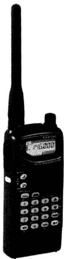
(1) Antenna Jack
This BNC jack accepts the supplied YHA-52 flexible antenna, or another antenna designed to provide 50-Ω impedance on the 2-m band.
(2) EAR Jack
This 2-conductor, 3.5-mm mini phone jack provides audio output for an optional earphone or speaker/mic (impedance is 8Ω). The internal loudspeaker is disabled when this jack is used. Note: the protective rubber cover over the jacks must be pulled up to access them.
Press it back over the jacks when they are not in use, to protect the inside of the transceiver from dust and water.
(3) MIC Jack
This 2-conductor, 2.5-mm phone jack accepts microphone input from an optional microphone or speaker/mic (impedance is 2-kΩ). The internal microphone is disabled while this jack is used.
(4) DIAL Rotary Selector
Use this 20-position switch to tune, or select memories and other settings such as tuning steps and paging codes, according to the function selected by the keys. This knob can be set to duplicate some functions of the SQL / SQL keys for convenience (page 50).
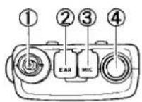
(5) VOL / SQL / VOL buttons
These buttons adjust the volume of the receiver in 32 small increments, indicated in the vertical bargraph at the left of the display. Also, the squelch is adjusted in the same manner after first pressing the BM key. This sets the threshold level at which received signals
(or noise) open the squelch. It should normally be set just to the point where noise is silenced (BUSY/TX lamp is off) when the channel is clear.
(6) ▲LOCK Switch
This slide switch locks the front-panel controls and buttons. Four locking modes are selectable: keypad, PTT, DIAL and volume level, in various combinations.
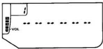
(7) BUSY/TX Indicator Lamp
This LED indicator glows red when transmitting, and green when the noise squelch is open (the channel busy) during reception.
(8) Front Panel Keys
These 18 keys generate DTMF tone pairs during transmission (except CALL & MSG), and select operating features of the transceiver during reception. One or two beeps sound whenever a key is pressed (unless the keypad beeper is disabled). The labels on the keyfaces indicate their primary functions, while labels on the panel indicate alternate functions, which are activated by momentarily pressing [FM] first, and then the desired key within five seconds.
For example, to use the alternate (Low Power) function of the ③ key, you press ☐M ^o followed by ③ within five seconds (in the manual, we indicate this by showing ☐M ^o → ③). There are also some "Setting Mode" functions, for customizing less-commonly used features. The Setting Mode is activated by pressing and holding ☐M ^o for >1/2 sec. (until the second beep sounds) then using the DIAL and ▲^/▼ keys to select and change function settings. All key functions are summarized in the tables on the next two pages (by key), and by function on the FT-11R Operator's Quick Reference Card. These are described in detail in the Operation chapter.
Side & Rear Panel
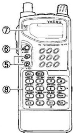
(1) PTT, Monitor (Burst) & LAMP Switches
The three buttons under the rubber cover are activated by pressing the ridges at the top (PTT - Push-to-Talk) center (Squelch override/Monitor or Burst), or bottom (Lamp) of the cover.
The rubber cover over the switches is intended to be permanent, and allows the switches underneath to be operated without removal.
text_image
Technical diagram of a walkie-talkie device with labeled parts including power switch and display screenPress and hold the (top) PTT switch while speaking across the front of the transceiver to transmit (the microphone element is in the center of the panel). While transmitting, the BUSY/TX indicator glows red, and pressing the front panel keys transmits a DTMF tone or tone sequence.
The center switch, in non-European versions, opens the squelch momentarily without dis-
turbing the squelch settings. Pressing ⒷM ^p first before the monitor button causes receiver audio to be muted ("MUTC" displayed) until the button is released.
In European versions, the center switch transmits a 1750-Hz tone, for repeater access.
Press the (lower) LAMP switch to illuminate the display and keypad when operating in the dark. Pressing only this switch activates the lamp for 5 seconds. Press ☐M° first if you want the lamp to stay on (until you press the switch again).
(2) Battery Release
Slide this mechanical button to the left to install a battery pack, and to release the battery for removal.
(3) POWER switch
To turn the transceiver on, gently press and hold this orange switch for 12 sec. Do this again to turn the power off.
LCD Indications
text_image
Low TX Power Memory Box Memory Scan Skip Memory Tune VOL/SQL Preset Level Bargraph Ind. Volume Lock Page Code Enabled PTT Lock Paging Message Mode Enabled Keypad Lock Dial Lock CTCSS Encode CTCSS Decode Repeater Shift Pager Alert Ringer 146 LOW T SQ - + 146.0 125 LV MSG T.PAGE CODE SAVE KL DL F 1 3 5 7 9 DTMF Memory Autodialer APO Timer On CTCSS Bell 12.5 kHz Steps Low Batt. Power Rx Pwr Saver Rx S-Units Rel. Tx PwrKey Functions
| Key | Normal Function | Alt Function (after pressing [RM]) " F" displayed for 5 secs. |
 | Enter digit 1 | Toggles CTCSS Encode/Decode Mode: T/T SQ / off. Note: FTS-26 (optional) must be installed for Tone Squelch (Decode ) and CTCSS Bell function. |
 | Enter digit 2 | Toggle display of CTCSS tone frequency (use DIAL to select tone) or enable/disable keypad key beeper (press [AM] key - "b" appears in memory box) |
 | Enter digit 3 | Toggle High/3-step selectable Low Tx Power. Low TX power level selected using DIAL knob or [▲]/[▼] keys (LOW1, LOW2 or LOW3). |
 | Enter digit 4 | Display / select power saver interval (sleep ratio):use DIAL knob or [▲]/[▼] keys to select the desired ratio, automatic or off. |
 | Enter digit 5 | Enable/disable Auto Power-Off feature, and select power-off timer period (10, 20 or 30 mins.) |
 | Enter digit 6 | Toggles repeater shift direction: - / +/ off (simplex). |
 | Enter digit 7 | Display/select tuning steps size (use DIAL to select default steps of 5, 10, 12.5, 15, 20, 25 & 50 kHz. |
 | Enter digit 8 | Display state TX Save feature- press [▲]/[▼] keys to toggle on/off. |
 | Enter digit 9 | Toggle repeater shift reverse |
 | Enter digit 0 | Activate "set-function" mode: " F" displayed for 5 secs., DIAL knob selects any of 13 functions, [▲]/[▼] keys change default settings. |
| Key | Normal Function | Alt Function (after pressing RM^ )“F” displayed for 5 secs. |
 | From VFO: recall last-used memory channelFrom Memory: enable memory tuning“M TUNE” | From memory mode only: toggle scan skip of currently selected memory channel. |
 | Enable ALT function of following pressed key(“B” displayed) | Cancel ALT function (while “F” is still displayed.) |
 | From VFO: select VFO “?” or “b”From Memory: select last-used VFO | Activate Priority monitoring |
 | Jump to CALL channel | Toggle DTMF autodial memory mode (“A” displayed). |
 | Enables Paging Message programming | Activates the Message receive system, when activated from within DTMF Paging or Trigger Paging Mode |
 | Tune up/down a step or memory, press and hold to start scanning (band or channel) | Tune up/down in 1 MHz steps |
 | Display/select preset volume level | Display/select preset squelch level. |
 | Toggle Paging/Trigger Paging/Code Squelch and CTCSS Bell Functions | Display/select DTMF Code memories. |
Accessories
Batteries & Chargers
The FT-11R requires the FNB-38 9.6-volt rechargeable Ni-Cd battery pack for the full 5-watt transmitter power output. However, where slightly lower maximum power output is practical, the 7.2-volt FNB-35 (providing 4 watts) and the 4.8-volt FNB-31 and FNB-33 Ni-Cd packs (1.5 watts) offer smaller size, lighter weight or extended battery charge life. Also, when using the PA-10 Mobile Power Adapter, the Ni-Cd packs may be recharged whenever the radio is inserted into the adapter. Any Ni-Cd pack should be fully charged before it is used with the transceiver for the first time.
Three types of battery chargers are available: 15-hour CA-9 Charging Stands, the NC-50 Dual-Slot Rapid Charger (used with CA-10 Charger Sleeves) and the internal charging circuit provided by the PA-10 Mobile Power Adapter and an external DC voltage source.
Different 15-hour compact chargers are required for different packs:
| Ni-Cd Pack | Voltage (DC) | Capacity (mAh) | Compact Charger |
| FNB-31/-33 | 4.8 | 600/1200 | NC-55B |
| FNB-35 | 7.2 | 900 | NC-34B |
| FNB-38 | 9.6 | 600 | NC-38B |
Ensure you use the correct charger for each pack. Each compact charger is available with a "B" suffix for operation from 117-V AC, or with a "C" suffix for operation from 220\~234-V AC.
NC-50 Dual-Slot Rapid Charger
The NC-50 is a universal AC mains battery charger with rapid and trickle charging modes, and comes wired for the mains voltage in the area sold. Up to two CA-10 Charger Sleeve units fit into the base of the NC-50, allowing different Yaesu Ni-Cd pack series to be charged.
The rapid mode is automatically selected initially, to bring the battery pack up to full charge as fast as safely possible using a -V sensor. A red LED lights during quick charging, and when the pack approaches full charge, the charger reverts to trickle mode (green LED), to prevent self-discharge. The rapid mode recharges a battery in about 1 hour.
PA-10 Mobile Power Adapter
The PA-10 charger/power adapter provides operating and battery charging voltage from an automobile electrical system or other DC source. Designed for the car door or dashboard, it allows convenient and safe mobile operation. Dual flexible latching arms facilitate easy insertion and removal of the FT-11R, while providing a secure transceiver mount for battery charging and operation in a mobile environment. Use only with 12-volt negative-ground electrical systems.
The PA-10 provides regulated 11-V DC output for operating the transceiver and for trickle-charging NiCd batteries when the transceiver is not in use. When the transceiver is inserted into the hanger, an LED turns on to indicate charging is taking place, and the transceiver display automatically illuminates for easy night-time viewing (unless the feature is disabled).
In addition, placing the transceiver in the PA-10 cradle automatically activates an internal fan, cooling the rear heatsink of the radio during extended or high-power transmissions (see the warning box on page 21).
natural_image
Line drawing of a mechanical device with no visible text or symbolsPA-10 Mobile Power Adapter
FBA-14 Dry-Cell Battery Case
The FBA-14 dry-cell battery case may be used with four "AA"-size (UM-3) batteries. Maximum power output is about 1.5 watts. Use alkaline cells for best performance.
Caution! The FBA-14 must not be used with rechargeable cells. It lacks the necessary thermal and over-current protection circuits provided in the FNB series Ni-Cd Packs.
One or more of the above battery packs/cases may be supplied with the transceiver. If you need a battery, contact your Yaesu dealer. We do not recommend the use of any other type of battery with the FT-11R, and using another type may affect your warranty.
Battery Removal & Replacement
☐ Make sure the power is switched off, and remove the protective soft case, if used.
☐ Grasp the transceiver horizontally with your left hand, so your thumb is on the Battery Release Button.
☐ Move the button in the direction indicated by the arrowhead, while using your right hand to slide the battery case up slightly and outward away from the transceiver battery well. The battery should slide smoothly out of its track.
To open the FBA-14 battery case, place your thumbs on the lugs on top of the case and gently pry the case apart. Always replace all four batteries, paying attention to the polarity indicated inside the case.
✗ Do not attempt to open any of the rechargeable Ni-Cd packs, and do not install rechargeable cells in the FBA-14, as they could explode if accidentally short-circuited.
To replace the battery case or Ni-Cd pack, repeat the second and third steps above, inserting the battery case in the other direction after aligning the four locking lugs of the battery case with the guide channels in the transceiver battery-well sides.
text_image
Battery RemovalNotice
When battery voltage approaches the level where recharging or pack changeout is necessary, the "☐" icon blinks. We recommend replacing the battery or inserting the transceiver into its charger at this time.
If the battery voltage is allowed to decline further, the display blinks and the tranceiver PWR switch no longer functions (transceiver cannot be switched off). Recharge or replace the battery pack immediately.
MH-12A2B & MH-18A2B Speaker/Microphones
A Speaker/Mic can increase operating convenience and extend communications range. Each is equipped with a dual plug connector which mates with the EAR and MIC jacks on the top panel of the transceiver, disabling the internal speaker and microphone. The cable lets you clip the transceiver to your belt, or hold it above obstructions for better performance. Also, using a Speaker/Mic for mobile operation allows the transceiver to be left in the PA-10 Mobile Power Adapter/Mount.
Hold the Speaker/Mic close to your ear during reception; or connect an earphone to the plug on the Speaker/Mic, attenuating the audio from its loudspeaker. To transmit just hold the Speaker/Mic close to your mouth and close the PTT switch on the microphone.
MH-19A2B Earpiece/Microphone
The MH-19A2B works like the Speaker/Mics described above, but consists of an earpiece and in-line microphone/PTT switch element. The earphone is inconspicuous and ideal for monitoring in noisy or crowded areas, while the microphone has a clip for attaching to a shirt or jacket collar. Press the PTT switch on the microphone to transmit.
VC-22 VOX Headset with Boom Microphone
The VC-22 connects to the EAR and MIC jacks in the same manner as the speaker/mics. It consists of a headband-supported earphone and attached boom microphone, allowing hands-free VOX operation with the transceiver.
Antenna Considerations
While the supplied rubber flex antenna is convenient for short-range operation, the standard BNC jack allows use of a higher gain antenna to extend range in base or mobile operation. Any antenna used with the FT-11R should have an impedance close to 50 ohms on the 2-m band. If a feedline is used, it should be good quality 50- coax. Obtaining a proper fit with some BNC plugs may require removing the rubber gasket around the antenna jack on the transceiver.
Operation
This chapter describes the various transceiver functions tutorially. After studying these descriptions, keep the FT-11R Operator's Quick Reference Card handy to refresh your memory.
Preliminary Steps
Before operating the FT-11R the first time:
☐ Charge the battery pack completely (if using Ni-Cd batteries) as described on page 11. If using an FBA-14 dry-cell battery case, install the batteries as described on page 13.
☐ Connect the supplied antenna to the antenna jack on the top of the transceiver. Never operate the transceiver without an antenna connected.
☐ If you have a Speaker/Mic, we suggest you not connect it until you are familiar with basic operation.
Before proceeding, please read the Controls & Connectors chapter, if you have not already, to familiarize yourself with the functions of the controls. Note especially the display on page 8, and the key information on pages 9 & 10.
When you press the front panel keys during reception, one or two beeps sound to indicate key contact. Don't hold the ⒺM° key down unless you are storing a memory, and try to avoid pressing two keys at the same time. While transmitting, the keys generate DTMF tones according to their numeric label or the blue A, B, C, D, *, # label (near the non-numeric keys).
You need not be too concerned about the following descriptions of timers - they are much easier to understand (by doing, which we will get to shortly) than to describe.
A several-second timer starts when you press ^D , and automatically restarts when you turn the selector knob or press or . Press-
Low Battery-Power Indicator
When the battery voltage drops to 4.0 volts, the "☐" indicator begins blinking, indicating the battery pack should be recharged or batteries replaced. Tx power automatically drops to 0.3 W, and if you continue operating, the transceiver turns itself off.
Keypad Beeper
You can turn the keypad beeper on and off by pressing ABC2 , then toggling the key ("b" appears in the memory box window when enabled). If you lock the keypad (as described later) with the beeper enabled, each key sounds a different musical note for as long as it is held. Press ABC again to return to normal operation.
ing other keys may shut off the timer as the resulting change in operation occurs, or restart the timer so you can select various functions.
The beeper provides useful audible feedback whenever a key is pressed. Each key has a different pitch, and many functions have unique beep combinations. For example, you will hear a low-pitched beep followed by a high-pitched beep when you press ⬆, or a high-pitched beep followed by a low-pitched beep when you press ⬇. You can disable the beeper as described in the box above, but we recommend keeping it enabled while getting to know the key functions.
With that said, if you have trouble getting the transceiver to work as described, see In Case of Problems, on page 55.
Volume Setting
Press either of the / buttons to adjust receiver volume, which is indicated on the 8-segment vertical LCD bargraph at the left edge of the display. If there is no signal, you can temporarily override the squelch by holding the center MONI button (below the PTT switch), while adjusting the volume on background noise.
Squelch Setting
Squelch silences background noise when no signal is present on the channel. You adjust the receiver squelch using the / buttons after pressing (within 3 seconds). While setting the squelch, "SQL" appears followed by a number ( 1 8 ) indicating the squelch level. Also, as with volume, the vertical LCD bargraph provides a visual reference of the selected level. Below about level "3", the BUSY/TX LED glows green, indicating the squelch is open. To set the squelch:
☐ After setting the volume to a comfortable level, if a signal is present, turn the DIAL to an empty channel (no signal, or only noise).
☐ Press (AM) and then or just to the point where background noise is silenced and the LED is extinguished. (If the squelch is set to a higher level, sensitivity to weak signals is reduced.)
Now, whenever a signal reaches the receiver strong enough to open the squelch, the BUSY/TX indicator glows green.
Note that while receiving, one or more bargraph segments may appear along the bottom of the display, indicating received signal strength. This is not affected by the squelch, so even squelched signals can give some indication. If several bargraph segments appear while the squelch is closed, try reducing the squelch setting (if you want to hear weak signals).
In non-European versions, the monitor switch (the center ridge below the PTT) opens the squelch so you can check for weak signals, and adjust volume independently.
Frequency Selection Modes
VFO Mode
This mode is for tuning or scanning the band when looking for a channel on which to operate, when you don't have a specific frequency in mind. In this mode, the DIAL knob and arrow keys each tune the band in the selected step size, or in 1-MHz steps, and the scanning function tunes in the selected step size. The FT-11R has two independent VFOs, A and B, which you toggle between by pressing (VFO) when receiving on either VFO. The memory box at the upper-left of the display shows which VFO is currently selected.
Memory Mode
This mode is mainly for operating on specific channels known in advance (and stored in the memories). For example, after storing the frequencies of your local repeaters, you can confine operation to those channels by selecting the memory mode. In this mode, the DIAL, ^MHZ / ^MHZ keys and scanning function select sequentially from stored memories. The FT-11R provides up to 146 memories (plus 5 special-purpose memories), each of which can store re-
peater shift direction, CTCSS settings (if the FTS-26 option is installed), and separate receive and transmit frequencies.
Each memory has a Memory Tune mode which lets you tune just like the VFO mode, and store the resulting re-tuned memory into the same or another memory. This and other special memory mode functions are described later, but you will want to keep these terms in mind.
You can tell at a glance which frequency selection mode is active by looking in the outlined memory box at the upper left corner of the display. If a small "R" or "b" appears in the box, you are in the VFO mode. If you see a small number or an "L1/L2", "U1/U2" or "C" in the box, you are in the memory mode.
The SKIP key switches from the VFO mode to the last-used memory, and VFO switches from the memory mode to the last-used VFO. While in the memory mode, your previous VFO mode selections are preserved.
Frequency & Step Selection
You can select a new frequency from a VFO, or by tuning a memory. For now, we suggest using the VFO mode. If you see a memory number in the memory box, press VFO to switch to VFO mode. You can enter a new frequency directly by the numeric keys, or by tuning with the DIAL knob or ▲ and ▼ keys. See Locking the Controls on page 32 if the keys or DIAL doesn't work.
Direct Numeric Keypad Entry
To enter a new frequency directly, just press the 10's and 1's-of-MHz digits, and the 100's- and 10's-of-kHz (if your version receives outside the 140- to 150-MHz range, press the 10's-of-MHz digit first). When you press the first key, the display clears and only the new digit appears. When you press the last key, the display reverts to normal, showing the new operating frequency to 6 digits (if it's valid), or the original frequency (if it was not: 2 beeps sound).
Example: To operate on 146.94 MHz:
☐ Press 4 6 9 4 and, if a trailing zero doesn't appear, 0 .
If your set covers the 146- to 147-MHz range, you should now see "146.940" displayed as your operating frequency. Otherwise, you should have heard 2 beeps, and the display should be as before (try an in-band frequency).
If your set is using 12.5- or 25-kHz steps, nothing happened when you pressed 4 , since this frequency is not a multiple of these steps. Just press any other number (except 9 ) to get the nearest resulting 12.5-kHz channel. Notice that you can enter 12.5-kHz splinter channels this way, but subsequent tuning is still in the selected step size, if it is larger.
Tuning
You can turn the DIAL or press the ^M+1 / ^M+2 keys to tune in the selected step size. If you press and hold a ^M+1 / ^M+2 key for continuous tuning, you need to release it and then press it again momentarily (to stop, and prevent scanning). One-MHz steps are also available: just press before pressing either of the ^M+1 / ^M+2 keys (and hold for repeated stepping), or press and turn the DIAL.
Default channel (tuning) steps are 5 kHz in A versions, and 12.5 kHz in B versions. To select another step size, press ^ 7^STEP-PRS , turn the DIAL for the desired steps, then press the PTT to return to normal operation.
Transmitting
Press → 3 , once or twice to select low power output (see box on following page). and “L” (followed by a level selection number) appears in place of the frequency, with “LOW” also displayed above and to the left.
To transmit, wait until the channel is clear (BUSY/TX LED off), then press and hold the PTT while speaking into the microphone (near the center of the front panel). During transmission the BUSY/TX indicator glows red, and the horizontal bargraph meter shows relative transmitter power output. Release the PTT to receive.
If you need more power to maintain communications, you can select another power setting as described in the box. However, we recommend using the lowest power level necessary to maintain communication to both maximize battery life and minimize possible interference to other stations.
If using a European version, press the center ridge of the rubber pad on the left side (just below the PTT switch) to transmit a 1750-Hz Burst Tone to access repeaters that require it.
Transmitter Power Selection
To toggle between high and low power settings, press ③M→③, and ③ again ("HIGH" or "LOW"). With "LOW" displayed, you can select one of three low power settings (LOW1, LOW2 or LOW3) by rotating the DIAL or using the ▲/▼ keys to select the desired power level (refer to the table below). The horizontal bargraph segments at the bottom of the display provide a visual reference of each power level setting both now and during transmit. Press the PTT or wait 3 seconds to save your selection and return to the frequency display.
| Display | @4.8 VDC | @7.2 VDC | @9.6 VDC | |||
| watts | mA | watts | mA | watts | mA | |
| LOW1 | 0.3 | 450 | .3 | 450 | .3 | 450 |
| LOW2 | 1.5 | 950 | 1.5 | 800 | 1.5 | 800 |
| LOW3 | 1.5 | 950 | 3 | 1200 | 3 | 1000 |
| HIGH | 1.5 | 950 | 4 | 1300 | 5 | 1500 |
*all power output and DC current values listed are approximate
Repeater Splits
The FT-11R offers three methods to set up split transmit/receive operation for repeaters: manual, automatic and independently stored Tx/Rx frequencies. Both manual and automatic methods shift the transmit frequency above or below the receive frequency by a programmable offset, preset at the factory to 600 kHz. Note that only one offset at a time can be used with the manual and automatic methods. Use the independent transmit frequency method when you want to store other offsets, such as frequencies of repeaters with non-standard splits. This is described later under Storing Independent Transmit Frequencies.
To activate the standard shift manually, just press 6 for minus shift, and press again for plus shift, and again to return to simplex. A small “-” or “+” sign appears near the top center of the display to indicate the current shift direction, when activated.
Example: To operate through a 146.34/146.94 MHz repeater (or substitute another pair if this is not used in your area):
☐ Tune the display to 146.94 MHz (to receive on the output frequency).
☐ Press ☐M→RPT MNO 6 once. A “-” should appear at the top of the display (if not, press RPT MNO 6 again until it does).
☐ When the channel is clear, press the PTT and send your callsign. The display shifts to 146.34 MHz while you transmit.
Of course this example only works if the offset is set to 600 kHz, as supplied from the factory. You can change it as described next.
With repeater split activated, you can temporarily reverse transmit and receive frequencies by pressing → 9 . Use this to display the transmit frequency without transmitting, and to check the strength of signals on a repeater uplink frequency (to see if you can work them direct). The repeater shift sign blinks while reverse split is selected. Press → 9 again to return to the normal shift direction.
Setting Standard Repeater Offset
As just mentioned, repeater offset is preset to 600 kHz. If you need to change the offset, first read the following steps, and then try them:
☐ Press ☐M→SET, then rotate the DIAL so that "☐" appears in the memory box to display the
current offset in MHz, to three decimal places ("0.600").
☐ Select the desired offset with the A/ B buttons. Resolution is 50 kHz.
☐ Press the PTT to return to normal display.
You probably want to keep the repeater offset programmed to the most commonly used split
Caution!
Avoid transmitting at high power (5 W) for extended periods of time to prevent overheating the radio (especially during 9.6 volt operation). A sensor in the FT-11R monitors internal temperature and automatically reduces transmit power to protect your radio if it gets too hot.
If this occurs, a blinking "LOW" indicator turns on, and the transceiver automatically switches to low power output. You should stop transmitting at this time and let the set cool down. Continued transmission will cause the protective feature to inhibit transmitting completely until the transceiver has cooled down sufficiently.
in your area. If you're not sure what that is, leave it set to 600 kHz.
Automatic Repeater Shift
The ARS (Automatic Repeater Shift) feature in the FT-11R activates repeater offset automatically whenever you tune to the standard repeater subband. With this feature enabled, a small "-" or "+" at the upper center of the display indicates that repeater shift is active (without your having to activate repeater shift manually), and closing the PTT changes to the (shifted) transmit frequency. The subband range over which ARS operates is determined by the version of your set, as shown below.
The ARS function is disabled at the factory. To enable it:
☐ Press 0 , and rotate the DIAL as before to display the current repeater shift (offset).
Now you can press Ⓜ(alone) to toggle the ARS function on and off ("") displayed to the left of the offset when activated).
☐ Press the PTT switch to return the display to the operating frequency.
As already mentioned, you can use the manual shift method ( → 6 ) at any time to select a new shift state, whether ARS is activated or not. However, if you change frequency with ARS activated, manual repeater shift selections are canceled.
Simple Memory Storage
The FT-11R offers 151 programmable memory channels, labeled I through M5,L1,L2,U1,U2 and C. Each can store separate receive and transmit frequencies or repeater shift, and CTCSS tone data (if the FTS-26 option is installed). Memory "C" (the CALL channel memory) can be recalled instantly by the button at the
Automatic Repeater Shift - Repeater Subbands
bar
| Version | Value | |---|---| | Version A | 145.1 | | Version A | - | | Version B | 145.6 | | Version B | - | | 145.5 | 145.5 | | 146.0 | 146.0 | | 146.4 | 146.4 | | 146.6 | 146.6 | | 147.0 | 147.0 | | 147.4 | 147.4 | | 147.6 | 147.6 | | 148.0 | 148.0 | The bars represent the difference between positive and negative outcomes for each version.upper left, and the L & U memories can be used in pairs to store programmable tuning and scanning limits, described later, in addition to general purpose operation.
To store a frequency in memory:
☐ Select the desired frequency (and repeater split manually, if desired) in the VFO mode as already described.
☐ Press and hold ☐ for 12 -second (until a second beep sounds). A memory number or letter appears blinking in the memory box.
☐ Within five seconds of pressing , turn the DIAL or press or to select the desired memory for storage. If you select one that was already being used, it will be overwritten with new data in the next step.
☐ Press ☐ once more momentarily to store the displayed data into the selected memory. The memory label will stop blinking for a second, and then disappear as operation continues in the VFO mode.
If you timed out, nothing new will have been stored in the memory. Simply start again.
Example: Store the 146.34/146.94 repeater data in memory 5.
☐ First perform the steps in the example on page 18 to set up the desired frequency and offset on the VFO.
☐ Press and hold ☐M° for 12 -second to display the memory label (blinking) in the memory box, then do the next step within 5 seconds.
Turn the DIAL or press the ▲A or ▼ keys, if necessary, so that "S" (the memory number to store) blinks in the memory box.
□ Press (FM) again, momentarily. That's it. The VFO data has been stored in memory 5, and you are left operating on the VFO.
To confirm that this worked, turn the DIAL to change the VFO frequency (to anything new), then press to change from VFO to memory mode. The numeral 5 should appear in the memory box, and 146.940 (the receive frequency) should appear on the display. As mentioned before, you can press 9 to confirm the transmit frequency of 146.34 MHz.
You can use any memory (except C, the CALL channel) with the same result. Memory C requires a slightly different procedure. Notice that pressing (MR) from the VFO mode always recalls the last stored or used memory.
Recalling Memories
In confirming the results of the last example, we used SKIP to change from the VFO mode to the memories after they were stored. The memory label appears in the memory box at the upper left corner of the frequency display whenever operating on a memory.
When more than one memory has been stored, you can select a memory for operation with either the selector knob, the and keys, or by direct keypad access. If you use the arrow keys, press and release the key for each memory: if you hold the key down for 12 -second, memory scanning will start. In any case, only pre-stored memories are displayed: empty memories are skipped. For direct keypad access, simply enter the number of the memory channel you want, followed by the key.
Example: to access memory channel 15, simply press 15 .
Note: for memory channels 100 \~ 151, you only need to enter the memory number (MR·key is not needed).
To exit the memories and return to the last-used VFO, press VFO#.
Call Channel Memory
Although invisible to the memory recall methods just described, the CALL channel memory can be instantly recalled by the CALL button: "L" appears in the memory box. The factory default for the CALL channel memory is the bottom edge of the band. You can re-program it with any frequency and repeater state, or even a separate transmit frequency.
To store the current VFO frequency/repeater state in the CALL channel memory, hold for 1/2 -second to display something in the memory box, then press . To store a separate transmit frequency in the CALL channel, after storing the receive frequency, tune the VFO to the transmit frequency and repeat the above, but this time holding the PTT switch while you press .
Storing Independent Transmit Frequencies
All memories can store an independent transmit frequency, for operation on repeaters with non-standard shift. To do this:
☐ Store the receive frequency using the method already described under Simple Memory Stor-
age (it doesn't matter if a repeater offset is active).
☐ Tune to the desired transmit frequency.
☐ Press and hold ☐M ^p for 1/2-second to display a label in the memory box again.
☐ Press and hold the PTT switch while pressing ☐ once more momentarily (this does not key the transmitter).
Whenever you recall a separate transmit frequency memory, “- +” appear together near the top center of the display. Again, you can press ^ 9 to display the transmit frequency, and the shift symbols will blink. You can also press ^ 6 to cancel repeater shift (temporarily, until you change channels).
After storing a memory with a separate transmit frequency, if you rewrite the receive frequency in that memory, the separate transmit frequency is deleted.
Memory Tuning
While receiving on a recalled memory, you can re-tune it and change other memorized settings (such as repeater shift) by first pressing MR. An "MT" symbol appears under the memory box, and you can tune in the same ways as described before (including 1-MHz steps). You can store the new frequency and settings in the current, or another, memory. Just press and hold for 1/2 -second, select the new memory (if desired), and press again momentarily. Operation remains on the (new) memory as the old memory reverts to its original state.
Once you have re-tuned a memory, if you don't want to save your changes, just press MR* to return to the original memory data.
Masking Memories
As already mentioned, storing data into a memory overwrites previously stored data. However, if you regularly move from one area to another, you may want to use different memories in different places or at different times. With the FT-11R, you can choose to make available different sets of memories without having to rewrite them from scratch. This is done by masking certain memories so that they are hidden from operation, and unmasking them only when desired.
To mask a memory,
☐ Recall the memory to be masked.
☐ Press and hold ^ for 12 -second (until the memory label blinks).
☐ Press SKIP MR*. The display changes to the next lower (stored) memory, and the previously selected memory is no longer selectable manually, or by scanning (described later).
To unmask a hidden memory for operation,
☐ Recall any memory.
☐ Press and hold ☑ for 12 -second (until the memory label blinks).
☐ With the DIAL knob or A/ B , select the memory number to be restored.
□ Press SKIP (not RM^D! ).
When you have hidden some memories, be careful not to overwrite them accidentally. If you do, you will not be able to recover the previous contents.
Naming Memories
The FT-11R allows you to assign alpha-numeric (A/N) names up to 6 characters long to the memories, and have those memories displayed by name rather than frequency. You can use this to identify channels by the names of friends, locations, ham clubs and repeater callsigns. Memories that have not been named are still displayed as usual, so you can mix and select the way memories are displayed. A choice of 48 different characters is available, with 12 special-purpose symbols that can be used to customize your name tags (see below).
Before using the A/N feature, however, there are a few important points to know:
- The transceiver must first be put into the A/N Mode before memories can be named. The programming steps explained later will not work outside of the A/N mode.
- The number of memories available for storage is reduced from 151 to 76 (1\~71, L1 & U1, L2 & U2 and C.
- When switching to the A/N mode, any previous stored memories will be lost! Therefore, if you plan to use the A/N feature, before pro-
Alphanumeric Character Set
| 0 | 1 | 2 | 3 | 4 | 5 | 6 | 7 |
| 8 | 9 | A | B | C | D | E | F |
| G | H | I | J | K | L | M | N |
| O | P | Q | R | S | T | U | V |
| W | X | Y | Z | ( ) | + | ||
| - | = | * | / | Δ | μ | Σ | : |
gramming many memory channels in the normal mode, we recommend you "start from scratch" programming your memories from within the A/N mode.
To place the FT-11R in the A/N mode, turn the transceiver off, the press and hold the MR* and VFO* keys together while turning the radio on again. The display and indicators appear as before, however, you will notice that when se-
Channel Memory Organization
| Ch. | Normal Operation | Ch. | A/N Operation |
| 1 | These memories store frequency / operational settings - can be masked from viewing and selection, and also tagged to be skipped during scanning. | 1 | All memories can be indexed with a 6-character name. Memory capacity is reduced by half, selection and settings remain the same. |
| 2 | 2 | ||
| : | : | ||
| : | |||
| 145 | 70 | ||
| 146 | 71 | ||
| L1 | Same as 1-146, but can be used in pairs to set upper & lower limits for PMS and Memory Tuning. | L1 | Same as 1-71, but can be used in pairs to set upper & lower limits for PMS and Memory Tuning. |
| L2 | L2 | ||
| U1 | U1 | ||
| U2 | U2 | ||
| C | Instant-recall CALL ch. | C | Instant-recall CALL ch. |
lecting and storing memories, only half as many are now available.
After programming frequency and operating settings into a memory, you can assign it a name.
☐ First recall the memory you wish to name.
☐ Press and hold ☐ for 12 second, then release it and press MSG. At this point the display should appear as below, with the numeral in the memory box blinking.
text_image
VOL☐ Rotate the DIAL. A character immediately appears blinking in the left-most place of the display. Continue rotating the knob until the desired letter (number or symbol) for the first place appears.
□ Next press CALL, this enters your selection in the first character's place, and moves to the next place to the right (the place remains blank until you rotate the DIAL, as before).
☐ Repeat the last two steps to enter characters into the desired places.
☐ When finished, press MSG to write the name to the memory. Operation remains on the memory. If you make a mistake when entering characters, start over from the beginning.
When naming memories, note that blank spaces can be entered in place of characters, and names do not have to begin at the first (leftmost) character's place. To leave the A/N mode
Tuning Named Memories
Named memories can be tuned just like unnamed memories ( DIAL or / ). The display automatically reverts to the operating frequency until memory tuning is canceled.
To change a named memory back to frequency display-only, recall the memory, press EM for 12 second or longer, then press the MSG button twice (MSG → MSG). However, this operation erases the A/N name completely, so it must be entered again.
(and lose all memorized settings!), perform the power on routine described at the beginning of this section (POWER → + ).
Scanning
Before scanning, make sure the squelch is set to silence background noise. You start scanning by holding A or B for 12 -second. If the transceiver is in the VFO or memory tune mode, band scanning will result. Otherwise, in normal memory mode, only the memories are scanned.
The scanner pauses when a signal opens the squelch, and the decimal point in the display blinks. When band scanning, a double beep sounds each time the scanner reaches the band edge, unless you have disabled the beeper ( ) → ABC → → ABC ). Scanning resumes according to how you set the scan resume mode, described in the box on the next page.
You can stop the scanner manually by pressing the PTT switch, or ▲/▼ keys, which will leave operation on the current frequency. Scanning is also halted by MR or VFO#, but operation shifts to the respective new frequency, in these cases.
Memory Skip Scanning
When you have some very active channels stored in memories, you may wish to skip them when scanning, but still have them available for manual selection. You can mark a memory to be skipped by pressing · while receiving on the memory. "SKIP" appears just beneath the memory box indicating that this memory will be skipped during scanning (although you can still recall it manually).
To cancel scan-skip and allow the memory to be scanned, just repeat the steps used to disable it: select the memory manually, and press ^ ^SKIP .
Programmable Subband (PMS) Limits
Besides band and memory scanning, the FT-11R can be set to tune or scan only between two frequencies of your choice (with the selected channel steps). The limits are stored in two pairs of special memories labeled L1 & U1 and L2 & U2:
☐ Store the lower edge of the desired scanning range in memory L, and the upper edge in memory U1 (or L2 & U2).
Scan Resume Mode Selection
You have a choice of two scan-resume modes: either Pause mode, in which the scanner pauses for as long as the carrier keeps the squelch open; or the 5-second mode, in which the scanner pauses for five seconds and then resumes scanning whether the signal is still present or not. The 5-second mode is the factory default.
To display the scan-resume mode, press , a small "F" or "S" appears in the memory box to indicate the currently selected mode. Press again to toggle the mode, and the PTT to return to the normal display.
☐ With either of the memories recalled, press SKIP MR* to enable memory tuning ("MT" must be visible below the memory box).
Your tuning and scanning range is now limited to the resulting subband. If ARS or manual repeater shift is activated, the offset is applied automatically when you transmit (even if the resulting transmit frequency is outside the sub-
band limits). Memories L^2 & U^2 work together the same way.
Note: The frequency resolution of subband limits is 100 kHz, although the channel resolution of the L & U' memories is the selected channel step size. Therefore, the actual limits are the frequencies stored in these memories rounded down to the nearest 100 kHz. Since the memories themselves are not limited to a specific frequency, you can still use them for other purposes anywhere within the 100-kHz range above the intended limit.
Example: To limit reception to 145.0 \~ 145.9 MHz
☐ Tune a VFO to any channel between 145.000 and 145.095 MHz.
☐ Hold ☐M° for 1/2-second, tune the DIAL so that the desired PMS memory channel (let's use L in this example) appears in the memory box, and then press ☐M° again momentarily. The displayed frequency is now stored to provide a lower subband limit of 145.000 MHz.
☐ Re-tune the VFO to any channel between 145.900 and 145.995 MHz.
☐ Repeat the second step, selecting U1 in the memory box. This stores the effective upper PMS limit of 145.900 MHz.
☐ Press ^SKIP * to change to memory operation, and then ^SKIP * again to activate the 145.000 \~ 145.900 limits. Tuning and scanning are accomplished in the usual way.
Note that with PMS, as with regular band scanning, a double beep sounds each time the scanner reaches the subband edge, unless you have disabled the beeper (page 16).
To release subband limits press to return to memory operation, to return to a VFO, or to switch to the CALL channel.
Once the L & U memory pairs are stored, you can reactivate PMS scanning and tuning just by recalling any PMS memory and pressing SKIP again. However, you cannot activate the subband if one memory of either PMS memory-pair is marked for skip-scanning, or masked (hidden).
Priority Channel Monitoring
The priority function automatically checks for activity on a memory every five seconds while operating on a VFO or other memories. When the receiver detects a signal on the priority memory, operation automatically shifts to that memory while the signal is present (plus a few seconds). If you transmit while paused on
the priority memory, priority monitoring ceases and operation stays on the priority memory.
To set up priority monitoring:
☐ Pre-set the squelch, and store the frequency to be monitored in a memory (this must be memory 1 if you will be operating on other memories during priority monitoring).
☐ Press VFO# to operate in the VFO mode, or else select the memory you want to operate on, and then press FM→VFO#.
A "i" appears in the memory box, and about every five seconds the displayed frequency shifts to the priority memory briefly while the receiver checks for a signal.
As long as no signal appears on the priority memory to open the squelch, you can tune, transmit and receive on the VFO, or select other memories (memory labels are displayed only while changing). If you hear a station you wish to talk with on the priority memory, press the PTT momentarily while receiving their signal, to stop priority checking. Otherwise, when a signal appears on the priority memory, priority checking pauses and the decimal on the display blinks. Priority monitoring will resume according to how you set the scan-resume mode — either after a 5-second pause, or after the carrier drops. To cancel priority monitoring manually, press VFO#.
Note that you can use any memory (besides memory 1) as a priority channel in the above procedure when you are going to be operating in VFO mode. You cannot, however, switch VFOs, or between memory and VFO operation (because pressing or cancels priority monitoring).
Memory-Only Mode
You can use this feature when you need very simple operation: only stored memories can be selected, and are displayed as "CH.1, 2,...", instead of the channel frequency or name display. Indictors for settings like repeater shift and tone squelch are still displayed, although they cannot be changed. In fact, the alternate functions of all numbered keys are disabled. Only the settings listed below can be changed as described.
• Hi/Low TX Power: use CALL to toggle
• Volume & squelch: same as before
• Channel Selection: DIAL or ▲/▼ keys
- Paging Messages: use MSG key to activate
After programming memories, you can toggle memory-only operation on and off by turning the radio off, then holding the MR* & EM* buttons while powering on again.
Locking the Controls
The PTT, keypad buttons, DIAL and volume level can each be "locked" (disabled), to prevent inadvertent transmissions or adjustments. You will find PL, KL, OL or possibly VL displayed singly, or in combination at the bottom center when any of these are locked. The locking switch is located just above the SQL keys, and is labeled "▲ LOCK". Slide the lever upward to lock and downward to unlock.
To set the locking scheme, press , then rotate the DIAL to select address "5" (displayed in the memory box) and so that "LOCK" appears in the display center. To select which functions to lock, press repeatedly for PTT lock (PL), key lock (KL) or both; or press for DIAL (DL), volume level (VL) or both. Finally, press the PTT momentarily to save your new setting and return the display to normal.
Lamp Illumination Settings
Pressing the LAMP switch beneath the rubber cover (underneath the PTT switch) momentarily illuminates the LCD and keypad for approximately 5 seconds, after which it turns off automatically. If you want to change this to continuous (press-on/press-off) illumination, simply press ☐ before toggling the LAMP switch.
When inserting the FT-11R into the PA-10 Mobile Power Adapter, the lamp turns on automatically, illuminating the transceiver for easy viewing when driving at night.
This factory default setting can be changed to manual illumination by pressing 0, rotating the DIAL for address "3" ("LMO,OUT"), then pressing either or to toggle from automatic to manual illumination ("LMO,OFF"). Press the PTT to save the change.
CTCSS Operation (with FTS-26)
The FT-11R can be used to access repeaters that require a CTCSS (continuous, subaudible) tone, and to silently monitor for calls on busy channels, when the optional FTS-26 CTCSS Unit is installed. The encode ("T") function superimposes a subaudible tone (at a frequency too low to be heard) on the transmitted carrier. The decode ("TSQ" — tone squelch) function monitors receiver audio through a narrow filter at the same subaudible frequency, keeping the squelch closed until you receive a matching tone. Installation instructions are at the end of the manual.
To check or set the current CTCSS tone frequency, press ③M^② to see the tone frequency displayed in Hz. To change the selected tone, turn the DIAL or press ^ or ^ until the display shows the tone frequency you require (the display steps through the standard EIA tones, listed in the table at the right). Press ② again alone to return to the operating frequency display.
To activate CTCSS functions, press ① when the operating frequency is displayed. With one press, "T" (encode) appears at the top of the display and the tone generator is activated for transmission. Press 1 again (or just ① if the alternate key functions are still active) and both "T" and "SQ" (decode) will be displayed together as the tone squelch system is activated for both transmit and receive (only incoming signals "encoded" with the matching tone open the squelch). To turn off the tone squelch features, press 1 once more.
You can store CTCSS tones (and encode/decode states) in each memory in the same manner
(and at the same time) as storing channel frequencies. To change the tone or state stored in a memory, just recall it, reset the tone frequency or function, and store the memory again (press and hold for 1/2 -second, release it, and press it again momentarily). If you activate CTCSS on a subband limit memory, it will be active when that memory is used to start subband operation.
CTCSS Tone Frequencies (Hz)
| 67.0 | 94.8 | 131.8 | 186.2 |
| 69.3 | 97.4 | 136.5 | 192.8 |
| 71.9 | 100.0 | 141.3 | 203.5 |
| 74.4 | 103.5 | 146.2 | 210.7 |
| 77.0 | 107.2 | 151.4 | 218.1 |
| 79.7 | 110.9 | 156.7 | 225.7 |
| 82.5 | 114.8 | 162.2 | 233.6 |
| 85.4 | 118.8 | 167.9 | 241.8 |
| 88.5 | 123.0 | 173.8 | 250.3 |
| 91.5 | 127.3 | 179.9 | — |
"CTCSS Bell" Paging
CTCSS Bell operation is an extension of the CTCSS encode/decode function described above: incoming subaudible tones open the squelch. However, it adds two features to make this semi-private operation more convenient:
(1) The CTCSS Bell mode displays "▼" at the right of the display. When you receive a matching CTCSS tone this bell blinks for a few moments to indicate you received a call. So, by looking at the display you can tell if a call came in. You cannot tell, however, who called. That requires DTMF Paging, described later.
(2) If you are waiting for a call, it is sometimes convenient to have the transceiver "ring" to get your attention. The alert ringer can be set to ring once, several times or can be disabled completely (see page 49).
To activate the CTCSS Bell:
☐ Tune to the desired frequency.
☐ Select a CTCSS tone frequency (BM)→TSET ABC as described on the previous page, if you have not already.
□ Activate tone squelch encode/decode operation ("T SQ") as described above.
☐ Press CODE/PAGE three times to select the CTCSS Bell mode. This cycles through the following paging mode/displays:
DTMF paging ("PAGE" displayed below the center of the display, and "") near the upper right if the ringer is enabled),
DTMF "Trigger" Pager ("T.PAGE" displayed, along with "") near the upper right, as above.
♦ DTMF tone-coded squelch ("CODE" displayed at the center),
CTCSS Bell paging ("") displayed if the FTS-26 is installed, and "near the upper right if the ringer is enabled), and
◆ No paging (none of the above symbols).
Now all incoming calls without a matching CTCSS tone will be ignored by your receiver. Any call received with the matching CTCSS tone will cause the "♥" to blink for 5 seconds and the transceiver to ring (if the ringer is enabled) as the squelch opens while the caller transmits. Note that other stations do not need to be using the
CTCSS Bell function to call you: they can use normal CTCSS functions of their transceiver.
When you reply to a CTCSS Bell call, you may want to turn off the CTCSS Bell function, since otherwise the transceiver will ring every time your squelch opens (unless, of course, you have disabled the ringer). Just press PAGE once to turn it off. If you have set up normal tone squelch operation beforehand, you will be able to continue your QSO.
You cannot store the CTCSS Bell mode selection in a memory, although you can store different CTCSS tones and encode/decode states.
DTMF Paging & Code Squelch
The FT-11R includes a DTMF (Dual-Tone, Multi-Frequency) tone encoder/decoder and a dedicated microprocessor providing paging and selective calling features. This allows you to place a call to a specific station or group, and to receive calls directed only to you or to groups of your choice.
The paging and code squelch systems use 3-digit numeric codes (000 \~ 999), transmitted as DTMF (dual, audible) tone pairs. There are twelve Code Memories numbered 1 \~ 2, 3, 4 and C, which store 3-digit DTMF paging codes (these are independent and unrelated to the channel memories and the VFOs).
Basically, your receiver remains silent until it receives three DTMF digits that match those stored in one of its code memories. The squelch then opens so the caller is heard, and in the paging mode, the paging ringer immediately sounds (see page 49). When you close the PTT to transmit, the same three pre-stored DTMF code digits are transmitted automatically. In the paging mode, three more DTMF digits are sent, representing the 3-digit identification code of the transmitting station.
Like the CTCSS Bell system described previously, the DTMF paging and code squelch systems are selected by pressing CODE. Either "PAGE", "T.PAGE" or "CODE" appears on the display when DTMF paging, trigger paging or code squelch is activated, respectively. The following descriptions begin with an overview of the various DTMF selective calling features, followed by details of actual operation.
DTMF Code Squelch
The code squelch mode is very simple: both you and the other station communicate using the same 3-digit DTMF sequence, sent automatically at the start of every transmission. Your receiver normally remains silent to all signals that are not prefixed by your selected 3-digit code. When you receive the matching tone sequence, your squelch opens and stays open until a few seconds after the end of their transmission.
In the code squelch mode, you must first store and then manually select the one Code Memory holding the 3-digit DTMF code required to open your squelch (as described on the following pages). Also, in the code squelch mode, Code Memories 1\~9 and 0 always function the same — the distinctions and special settings described below for the paging mode do not apply.
DTMF Paging
In the DTMF paging mode, you can receive signals that are prefixed with any of up to ten different 3-digit codes, according to the method you choose when programming the Code Memories. When you receive a paging call, the selected Code Memory changes automatically, and the display responds in one of two ways, depending on how you stored the paging code:
Individual Codes
These are unique personal ID codes to identify each station. You store one of these for your Personal ID, in Code Memory P. You can store one other Individual Code of a station you call often, in Code Memory 1. When someone else transmits your Individual Code, your transceiver automatically selects Code Memory C, and the calling station's Individual Code is installed in that Code Memory so you can see who called.
DTMF Code Memories
| ch | 3-digit DTMF Codes |
| : | Individual ID code of friend or frequently-called station stored here |
| 2 | Group ID codes stored here |
| ~ | “ ” “ ” |
| 9 | Group ID codes stored here |
| 0 | Your Group ID code stored here |
| c* | Automatically shows ID code of paging station — Rx-only, cannot be written to |
| p* | Your personal ID code goes here |
* memory cannot be selected for page-code inhibit
Group Codes (Code Memories 2 \~ 9)
This type of code identifies a group of stations. You would generally share a Group Code with other club members or friends. When you receive a call with a Group Code the Code Memory number in which you stored that 3-digit Group Code is selected and displayed automatically, so you can see which group has been called (if you have stored more than one).
Note that for a Group Code, the display does not show the ID and code of the caller, but those of the group instead. Code Memories 2\~9 can be used to store either Individual Codes (for calling purposes only) or Group Codes (for both calling and receiving), as you desire.
With either type of page, the PAGE indicator starts blinking when a page is received, and the ringer sounds, if enabled. The blinking indicator lets you know if someone called while your attention was elsewhere.
Remember, with code squelch operation (but not with paging), you can only receive a call on the currently selected Code Memory, and the display does not change when a call is received. So for code squelch, as mentioned before, the Individual/Group distinction does not apply (although you must still store the 3-digit Code Memories).
In either code squelch or paging modes, any DTMF-equipped station can call you. They can use a DTMF keypad to send the three digits if you are in code squelch mode, or seven digits (actually, three digits—"star"—three digits, e.g.: 123*456) if you are in paging mode.
DTMF Code Monitoring
Whenever a 3-digit DTMF code is received while either code squelch or DTMF paging is active, the code is automatically written into Code Memory C. By selecting this Code Memory as described below, you can determine what DTMF code was last heard, whether or not it opened your squelch.
Storing Code Memories
The first thing to do before using the paging or code squelch systems is to store your Personal Code in Code Memory P:
☐ Press ☐M ^o → ☐PAGE ^c to enable the Code setting mode. The frequency display is replaced by a Code Memory number at the left, and the corresponding 3-digit Code ("GIO", if not used before) at the right.
☐ Turn the DIAL to select Code Memory P, which is for your personal DTMF paging ID Code.
☐ Use the numeric keys to enter the three digits you want to use for your ID.
☐ Press CODE PAGE or the PTT to return the display to the operating frequency.
Your Personal ID Code is now stored in Code Memory P. You can use the same procedure to store the Memory Codes of other individuals or groups in Code Memories 1 \~ 9 and 0, but with an additional feature: generally you store another station's ID Code so you can page them, but do not want to have your transceiver ringing every time someone else calls them. On the other hand, you store group codes with the intention of receiving any pages to the group (so you want your squelch to open and the transceiver to ring, if paging). You can prevent your transceiver from ringing using Page Code Inhibit, described next.
Page Code Inhibit
During the Code Memory storage procedure above, when storing Code Memories 1 \~ 9 and 0, you have an opportunity to decide whether your transceiver should respond to incoming paging calls on a particular Memory Code. After pressing to activate Code setting you can press to toggle DTMF squelch paging capability on and off. When on, that is, when the decoder is enabled to receive paging calls with this Code Memory, a small underbar appears beneath the Code Memory digit.
If you are setting a Group Code, you want to have the underbar on, and if setting another station's Individual Code, you want it off. As already mentioned, this distinction does not apply to code-squelch-only (non-paging) operation — the underbar has no effect.
Note that the underbar is displayed permanently on Code Memory P, since this is your own ID (that you will always want to receive when paging is activated). Also, the underbar never appears on Code Memory C, since this is reserved for the display of incoming codes.
Once you have stored your own ID Code in Code Memory P, you can activate the paging or code squelch functions from the normal frequency display by pressing PAGE. As mentioned earlier in the CTCSS Bell procedure, repeatedly pressing this key cycles through DTMF paging ("PAGE" displayed), trigger paging ("T.PAGE"),
code squelch ("CODE"), CTCSS Bell paging ("▼"), and no paging (none of these symbols).
DTMF Code Squelch Operation
As described earlier, with DTMF code squelch activated ("CODE" displayed), your squelch will not open until you receive the proper 3-digit DTMF code according to the selected code memory. Likewise, each time you press the PTT, the same 3-digit code is automatically sent to open the other station's DTMF coded squelch.
Replying to a DTMF Page, and Resetting
Any DTMF-equipped station can call you by sending your 3-digit code, followed by their 3-digit ID Code. Your transceiver will ring (unless you have turned off the ringer, as described in the box on page 49), "PAGE" starts blinking, and the code of the calling station (now in code memory C) is displayed.
If you press your PTT switch after receiving a page, the transceiver sends the other station's ID code, a DTMF "star" (*) followed by your own 3-digit personal ID code (that is, Code Memory P) all automatically, and then resets the radio to receive another call.
DTMF Code Display Options
Normally, the Code Memory number is displayed in place of the 100's-of-MHz frequency digit whenever DTMF Code Squelch, DTMF Paging, or Trigger Paging is enabled (the rest of the frequency digits remain as before).
Also, the and keys rapidly select Code Memories, instead of tuning or scanning (DIAL operation remains unchanged).
If you want to scan while in these modes, you may prefer to enable the alternate Code Memory display feature, which displays DTMF Codes only after pressing CODE PAGE, or receiving a page.
To toggle this alternate Code Memory display option on/off, press , rotate the DIAL knob so that "L" appears in the memory box and "O" appears in the display center. Then press either or to toggle the optional Code Display "ON" or "OFF", and press the PTT to return to the normal display.
Unless you are using the Trigger Paging function (covered next), you may want to switch from paging to code squelch mode once contact is established. Just press PAGE once, so that "CODE" appears. Either you or the other station will also have to select Code Memory C, so that you will both be using the same DTMF code (either, but not both, must re-select their Code Memory). With the Code Squelch activated in this manner, you will hear three DTMF code digits transmitted when you press your PTT switch. These are the digits stored in the Code Memory currently selected (and displayed in place of the 100's-of-MHz digit if the Code Memory Display option is enabled), and they will open the squelch of the other station. Therefore, at the start of each transmission, you must wait a second or two after pressing the PTT switch for the DTMF code to be sent (you will hear it in your speaker).
When you finish your conversation, if you need to reactivate DTMF Code Paging, press three times until "PAGE" is displayed.
Trigger Paging
This feature is designed to overcome the inconvenience of having to manually switch to
Paging Tx Delay
When calling other stations using DTMF Paging or Code Squelch, particularly through repeaters, you may find that some are unable to receive your calls. This can be caused by their receiver squelch not opening fast enough (after receiving your transmitted carrier) to allow all of the DTMF digits to be received and decoded. To correct this problem, you can set a longer delay (750 ms) between the time your transmitter is keyed and the time the first DTMF digit is sent.
Press → , then rotate the DIAL to select "DIL" ("DIL" in the memory box). Press or to toggle from the default delay (450 ms) to "750" ms.
and from Code Squelch mode when responding to a page. It can only be used between transceivers equipped with this feature: such as the Yaesu FT-11R/41R, FT-530 and FT-2200/7200.
To activate Trigger Paging, press CODE PAGEc repeatedly until "T.PAGE" is displayed. When a call is received, "T.PAGE" blinks, and the alert ringer
sounds. If the other station is also using the Trigger Paging, communications can begin just by acknowledging the page: press the PTT and begin talking within three seconds after the DTMF code sequence is sent. The pager resets to receive a new call as soon as either station fails to respond to the other within three seconds.
Paging "Answer Back"
When you press the PTT to respond to a page call, the FT-11R transmits the callers ID code, followed by a DTMF "*" and your personal ID code. This informs the calling station that their page was received. If you prefer, you can have the FT-11R respond to page calls automatically ("transpond"). Use this feature in combination with Trigger Paging for virtually "hands-free" automatic paging operation (a received page is automatically answered and the squelch opened for immediate voice communication).
☐ To enable this feature, press ^ ^SET , rotate the DIAL until "0" appears in the memory box and "R3 .OFF" (factory-default) in the center of the display.
☐ Press or to toggle the answer-back function on ("TT", "MN"), and the PTT to return to the channel display.
Message Paging
This feature allows you to send and receive text messages up to six characters long. Two separate 10-channel memory banks are used for message storage: one for for received messages and the other for outgoing messages programmed using the FT-11R's alphanumeric 48-character set.
Storing Messages to Send
☐ Press and hold the MSG button for 12 second so that the display appears as below ("MSG" indicator blinks at the bottom of the display).
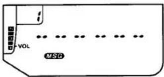
text_image
VOL MSG☐ Rotate the DIAL knob to select a message memory to program (number indicated in the memory box), then hold ☐ for 12 second (now both “” and the memory box numeral blink).
☐ Rotate the DIAL to select the first character of the message and press CALL to save the entry and move to the next place.
☐ Repeat the previous step until your message is completed. If you make a mistake entering a character, finish the rest of the message, then press the CALL button to step to the incorrect character, and enter the correction.
□ When your desired message is displayed, press MSG to save this entry. You can now use the DIAL to select another memory for message entry, or press MSG once more to finish.
Sending Pre-stored Pager Messages
Once a message has been stored, it can be sent using DTMF Paging or Trigger Paging:
☐ Press CODE PAGE until the desired paging mode (Paging or Trigger Paging) is activated, and select the Code memory of the station that is to receive the message.
☐ Press and hold the PTT while also pressing MSG, followed by the number of the memory containing the message you want to send. The text of your message is displayed as it is sent.
FT-11R Alphanumeric Character Set
| 0 | SET0 | A | TSET ABC2→▲ | MHz | K | APO JKL5→▼ | MHz | U | TX SAVE TUN8→▼ | MHz | n/a* | SET0→1M |
| 1 | TONE QZ1 | B | TSET ABC2→▼ | MHz | L | APO JKL5→PAGE | CODEPAGE | V | TX SAVE TUN8→PAGE | CODEPAGE | - | TONE QZ1→1M |
| 2 | TSET ABC2 | C | TSET ABC2→PAGE | CODEPAGE | M | RPT MINO6→▲ | MHz | W | REV WXY9→▲ | MHz | = | TSET ABC2→1M |
| 3 | LOW DEF3 | D | LOW DEF3→▲ | MHz | N | RPT MINO6→▼ | MHz | X | REV WXY9→▼ | MHz | * | LOW DEF3→1M |
| 4 | SAVE QHI4 | E | LOW DEF3→▼ | MHz | O | RPT MINO6→PAGE | CODEPAGE | Y | REV WXY9→PAGE | CODEPAGE | / | SAVE QHI4→1M |
| 5 | APO JKL5 | F | LOW DEF3→PAGE | CODEPAGE | P | STEP PRS7→▲ | MHz | Z | TONE QZ1→▼ | MHz | Δ | APO JKL5→1M |
| 6 | RPT MINO6 | G | SAVE QHI4→▲ | MHz | Q | TONE QZ1→▲ | MHz | ( | SET0→▲ | MHz | μ | RPT MINO6→1M |
| 7 | STEP PRS7 | H | SAVE QHI4→▼ | MHz | R | STEP PRS7→▼ | MHz | ) | SET0→▼ | MHz | Σ | STEP PRS7→1M |
| 8 | TX SAVE TUN8 | I | SAVE QHI4→PAGE | CODEPAGE | S | STEP PRS7→PAGE | CODEPAGE | + | SET0→PAGE | CODEPAGE | : | TX SAVE TUN8→1M |
| 9 | REV WXY9 | J | APO JKL5→▲ | MHz | T | TX SAVE TUN8→▲ | MHz | space | TONE QZ1→PAGE | CODEPAGE | n/a* | REV WXY9→1M |
Sending Pager Messages Manually
If you do not have a particular message in memory (or the time to store it), you can send it manually by using button combinations. Message format consists of a DTMF “#” followed by up to six message characters, ending with an additional “#”. When sending a pre-stored message, the “#”s are automatically inserted by the FT-11R's CPU. When sending messages manually, however, remember to include these.
Unlike DTMF numerals, which are entered with a single key, letters of the alphabet and other symbols each require a two-button key sequence. For example, generating the letter "7" requires manually entering 7 . So as you can see, sending messages manually takes a little practice and limber fingers. The table on the previous page shows the key sequences required to generate each character.
☐ Press CODE PAGE until the desired paging mode (Paging or Trigger Paging) is activated, and select the Code memory of the station that is to receive the message.
☐ Press and hold the PTT during all of the following: wait a few seconds for the paging ID codes to be sent, then press VFO*, followed by
your message, then VFO# again before releasing the PTT.
Receiving a Pager Message
To receive a message, your FT-11R must have either Paging or Trigger Paging activated along with the message function. Press (GM)°→MSG to activate the message function ("MSG" displayed). After receiving paging ID codes, the message is displayed and automatically stored in a incoming message bank (separate from the outgoing-message bank). Up to ten messages are sequentially stored in the receive message bank channels 1\~9 and 0, in the order received.
Likewise, messages subsequently received overwrite these on a first-in, first-out order, unless you have "single storage" selected (see the box on the next page).
To recall received messages from the memories, simply press the MSG button, then rotate the DIAL to select (and view) the desired memory.
To erase all pager messages, turn the transceiver off, then press and hold the MSG button while turning the power on again.
Message Bank Storage Mode
Received Paging messages normally overwrite the message memories once the ten memories are full. If you want to keep them from being overwritten, you can change the message storing mode:
☐ Press ⓂM ^o → Ⓞ, then select address "☐", so that "☐.NET" (the "continuous" default) is displayed.
□ Use ▲ or ▼ to toggle between continuous or single message storage ("TM").
☐ Press the PTT to save the change and finish.
Received messages are displayed as before, but now only the first ten will be stored in the message bank.
Message Display Options
Incoming Pager messages normally appear on the display as they are received. To have the display remain unchanged, so messages can only be recalled and displayed manually, change this default setting as follows:
☐ Press ^ → , turn the DIAL until address "C", and "M" RUT" (default) appears in the display.
□ Use ▲ or ▼ to toggle between automatic and manual "MI" .MIN" message display.
☐ Press the PTT to save the change and return the display to normal.
Now, when a message is received, you can manually view it by pressing MSG, then turning the DIAL to select the desired memory.
DTMF Auto-dial Memories
The FT-11R provides ten memories, numbered 0 through 9, for storing DTMF tone sequences of up to 15 digits each (see below). These can be used for remote DTMF control sequences or telephone numbers for auto-patching systems.
A special mode must be activated to use the DTMF auto-dial memory features. This mode is toggled on and off by pressing ^ . A “ ” is displayed above the rightmost frequency digit when this mode is active.
To store a DTMF memory:
☐ Press ⓂM ^D → ⓆALL, if necessary, to display the "電".
☐ Press and hold ☐ for 12 -second (until the second beep sounds), then within 5 seconds, press a numbered key corresponding to the
DTMF Auto-dial Memories
| ch | DTMF Digit Codes (up to 15 max.) | ||||||
| 0 | 1st | 2nd | 3rd | ...... | 13th | 14th | 15th |
| : | “ ” | “ ” | |||||
| : | “ ” | “ ” | |||||
| 9 | “ ” | “ ” | |||||
DTMF auto-dial memory number you want to store (or use the DIAL or A/ B keys). The display will resemble that shown below.
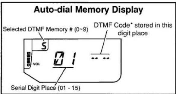
text_image
Auto-dial Memory Display Selected DTMF Memory # (0~9) DTMF Code* stored in this digit place S vol 1 ... Serial Digit Place (01 - 15)☐ Press and hold PM again for 12 -second ("m" begins to blink), and then key in the numbers of the DTMF sequence you want to store. As you do so, the serial digit place at the left side of the display increments automatically as the entered digit is displayed at the right.
Note: when entering new DTMF codes, the serial digit number on the display will be that of the next digit to be stored - not the serial number of the digit displayed at the right!
If you make a mistake, press the PTT switch to cancel your entries, and repeat the last step
(all digits must be re-entered). Remember: the "■" icon must be blinking before you can enter digits.
☐ If you are storing fewer than 15 digits, press CALL to terminate entry (if you are storing 15 digits, entry terminates automatically after the last digit).
☐ Turn the DIAL to select another DTMF memory to store, if desired, and repeat the last two steps.
☐ Press CALL to return to the frequency display.
Auto-dialer Playback
You can manually check the contents of DTMF auto-dial memories while "☐" is displayed:
☐ Hold ☐ for 12 -second, then press any numbered key (to change the display to auto-dial memories).
Turn the DIAL to select the desired auto-dial memory number (shown in the memory box), then use the A / B keys to display each digit. The serial place of the digit appears in the center of the display, and its DTMF code at the right.
☐ To replay the stored codes in the loudspeaker and on the display, simply press the numbered key corresponding to the DTMF autodial memory number stored.
To play back DTMF auto-dial memories on the air, first make sure the DTMF memory mode is activated ("☑" is displayed). Then close the PTT switch and simply press the number of the auto-dial memory to transmit. Once the DTMF sequence has begun, you may release the PTT (the transmitter stays keyed until the auto-dial string has been sent).
Note!
With the DTMF auto-dialer active, the keypad cannot be used to transmit individual DTMF codes. If you do not have the required DTMF sequence stored in memory, turn the auto-dial mode off by pressing CALL("B" turns off), then manually press the keypad buttons for the desired DTMF codes.
Naming DTMF Auto-dial Memories
The FT-11R lets you assign a name (up to 6 characters) to each DTMF auto-dial memory, to be displayed when the memory is recalled. This can help you to identify whose numbers you have stored. The same A/N character set and procedure used for naming regular memory channels (page 26) is used for auto-dial memory naming.
□ Activate the DTMF Autodial mode by pressing ⓂM ^o → ⓒALL (if necessary, to display the “ ”).
☐ Press and hold ☐ for 12 -second (until the second beep sounds). Then press the numbered key corresponding to the desired DTMF memory to be named.
☐ Press ^ to enter the A/N mode, then hold ^ for 12 -second. The number in the memory box starts blinking, and you can enter the A/N name (as shown below).
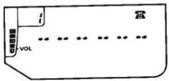
text_image
i VOL☐ Use the DIAL to select characters and the CALL button to move places. When finished with the last character, press MSG to finish.
□ When displaying DTMF auto-dial memories, the A/N mode can be toggled on/off by pressing ⓂM ^o → ⓆCALL.
text_image
HOMETECustomizations: the Setting Mode
Pressing activates the setting mode, which allows you to customize the performance of some functions to your taste. In this mode, the Memory Box shows the "address" of the selected function, from 1 to 13, and the frequency display is replaced with symbols to indicate the current function and its state. The functions are summarized in the table at the right, and described in more detail in the text at the indicated page. Rotate the DIAL to step through each of the 13 functions, and press or to change the state of the displayed function.
To exit the setting mode, press the PTT switch (no transmission will occur). The display returns to normal.
| Addr | Display | Function | Page |
| 1 | PIL.450*750 | Paging Tx Delay (ms) | 40 |
| 2 | BCLLO13S* | Paging Bell # rings | 49 |
| 3 | LMP.RUT*OFF | Lamp Oper. ext pwr | 32 |
| 4 | OP.ON*OFF | One-touch Paging | 39 |
| 5 | LOCK KL*DL PL VL | Lock Combinations | 32 |
| 6 | 0.600* | Rptr. Offset, ARS | 21 |
| 7 | MB.RUT*MON | Message Display | 44 |
| 8 | RB.OFF*ON | Answer-back Pager | 41 |
| 9 | MB.CNT*SIN | Message Bank Storage | 44 |
| 10 | MCL.INT*USR | Ringer Alert Melody | 51 |
| 11 | BM.BT*BC | DTMF Playback mode | 49 |
| 12 | BM.BC*BT | Keypad beeper mode | 49 |
| 13 | JS.F*S | DTMF Playback speed | 49 |
* factory default. To return all Set-Mode Function settings to factory-default (as above), turn the transceiver off, then press and hold VFO while turning it back on.
Ringer Settings
You can customize the ringer that alerts you to incoming calls during CTCSS Bell and DTMF Paging operation. To can change the number of rings ( =OFF, l, 3 or 5):
☐ Press → , and rotate the DIAL until "2" appears in the memory box and "RCL5" (default rings) in the display center.
☐ Press ▲ or ▼ for the desired number of rings, or "BELL" to disable the ringer completely.
☐ Press the PTT to save your entry and return the display to normal.
DTMF Settings
Following are a few alternate setting functions of the DTMF keypad that you can customize to your own preference.
Musical or DTMF Keypad "Beep"
Normally, pushing a key sounds a single-tone musical note in the loudspeaker. If you prefer, you can change the default musical beeps to DTMF tones by pressing , and rotating the DIAL so that “ i_L^2 ” appears in the memory box (“ i_M^2 . i_L^2 ” in the display center). Then press ^MHz or ^MHz once ( " ^M, ^T" ) and the PTT to save your entry and return the display to normal.
DTMF Memory Playback
Like the keypad beep selection above, the tones stored in the DTMF auto-dialer memories can be played back using single-tone musical notes instead of DTMF tones. You might want to select the musical notes if you are using memory 0 for the user-programmed ringer alert melody. Note, however, that while this setting is in effect, you cannot transmit the DTMF tones stored in autodial memories.
To change the memory tones, press ^D , turn the DIAL so that "!" appears in the memory box ("TM. TM" in the display center). Then turn the DIAL or press _z^A or ^B once ("TM. TM"). Press the PTT to save your entry and return the display to normal.
DTMF & Melody Playback Speed
You can toggle the playback speed of DTMF Auto-dial Memories (DTMF or musical beeps, if enabled). Note that this speed selection affects all tone playback in the FT-11R: Auto-Dialer, Page Codes and all Ringer/Alerting Melodies.
The default tone duration is 50 msec., resulting in a playback rate of about 11 digits per second (fast). This can be changed to 80 msec. duration, giving a playback rate of 7.5 digits per second (slow). To change the DTMF playback speed;
Press , and rotate the DIAL so that "13" is displayed in the memory box and "75.5" in the display center. Press or once ("75.5") to toggle your selection, then press the PTT to return the display to normal.
Volume Control with the DIAL
If you prefer to use the DIAL to control the volume setting, hold the SQL and 🔒 buttons while turning the transceiver on. Now, both the DIAL and 🔒/SQL buttons function the same, while VFO and memory tuning/scanning is limited to the 🔒/▼ buttons. For squelch adjustment, remember to press (FM) first and only use the 🔒/SQL and 🔒 buttons. Repeat the power-on procedure to return the DIAL to default behavior.
Extended Receive Range
The receive range (only) of the FT-11R can be extended to 110 \~ 180 MHz by a simple power-on sequence. Transmit range is limited to the amateur bands only. This feature may not be available on all versions, as reception outside of amateur bands is subject to regulations in some countries. If you are in doubt, contact your Yaesu dealer.
Turn the transceiver off, then press and hold both ▲ and ▼ together while turning the radio on again.
Tuning now extends from 110 to 180 MHz, with AM detector circuitry automatically activating below 136 MHz to enable reception of the aeronautical band. To return the FT-11R to default (amateur band only) reception, repeat the power-on sequence again.
Extending Battery Life
How long NiCd batteries last between charges or replacement depends largely on your operating habits, and how you care for the battery pack. The FT-11R offers several ways to conserve battery power, and extend the life of each charge. Knowing how to use these features can be critical in emergencies.
APO (Automatic Power-Off)
Obviously, turning the set off when not in use saves battery life, and can also prevent damage that might result to the batteries if they are over-discharged. The FT-11R provides the APO system to turn the transceiver off after 10, 20 or 30 minutes of key inactivity. From the factory, APO is disabled, but you can easily activate it by pressing 5 ("APO.OFF") and then rotating the DIAL (or pressing or ) to choose the time-out time (in minutes). Press the PTT to return the display to normal. When APO is activated, "☐" appears at the top right corner of the display, and a timer starts every time you press a key. If you don't press any keys for the selected time-out period, and as long as you are not scanning or priority monitoring, "☐" will be gin blinking, and if you have the key beeper activated (page 16), it will play an alert melody (see the box below) about a minute before the transceiver turns itself off. If you don't press a
APO Alert Melody
You can choose either the factory-initialized Alert-Ringer Melody or one of your own composition to be played back during the APO shut-down sequence. The user-programmed melody can be up to 15 notes long, and is stored in DTMF Auto-dialer memory 0 using the same procedure as described for DTMF Auto-dial Memories on page 45.
To select the default Alert-Ringer Melody, press and then use the DIAL to select "IO" in the memory box ("MCL.INT" displayed). Use the / keys to toggle between user- and initialized-melody ("MCL.USR") selections, then press the PTT to return the display to normal.
key in that minute, the transceiver turns off. After that, you must switch the transceiver back on for use. If you need to monitor for a long period, or if using an external DC supply, you can deactivate the APO feature by pressing the same keys as before, so the display shows "HPO.OFF"
Receiver ABS "Automatic Battery Saver"
Monitoring with squelch closed requires about one third the power of listening to unsquelched noise, so you will naturally want the keep the squelch closed as much as possible. The FT-11R uses an automated battery saver system originated by Yaesu, reducing current drain during squelched monitoring. The Battery Saver puts the receiver to sleep three seconds after the squelch closes, and then wakes it up for 200 milliseconds periodically to check for incoming signals. When the Battery Saver is enabled, a small "SAVE" appears near the bottom right corner of the display, which blinks when the saver is functioning.
You can select from eight sleep durations, from 200 ms to 1 second, or you can select the ABS function, which senses channel activity and dynamically selects a monitor/sleep ratio according to recent operating history.
The ABS mode is enabled as supplied from the factory. You can check or change the sleep duration or disable the Power Saver by pressing EM→4 and then rotating the DIAL to change the current (displayed) saver ratio. Possible selections and their corresponding keys are shown in the table below.
TX Save
One of the best operating habits is to always use the lowest transmitter power necessary to maintain reliable communications. As described on the box on page 20, the FT-11R offers a choice of four levels of power output: one HIGH and
Battery Saver Settings
| Display (ratio) | RX “On”- time | “Sleep”-time |
| 58.11 | 200 ms | 200 ms |
| 58.12 | 200 ms | 400 ms |
| 58.13 | 200 ms | 600 ms |
| 58.15 | 200 ms | 1000 ms |
| 58.07 | always on | — |
| 58.085 | 200 | variable* |
* see explanation in text
three low — LOW 1, LOW 2 and LOW 3. On top of this, the FT-11R can reduce transmitter current drain further with it's smart TX Save feature. This conserves battery life by reducing power output when the microprocessor determines it is not needed. It monitors the signal strength of the last-received signal and also checks for the presence of modulation when you press the PTT to transmit.
If a full-scale signal was sensed on the receive frequency (such as a repeater output) and the transmitter is keyed but you are not speaking (both conditions must be met), TX power is automatically reduced two levels from its present setting (ex. HIGH → LOW). Note that if you are using a 4.8 VDC battery, TX Save will have no effect (in actual power output) with the HIGH power level selected. Refer to the table on page 20 for power levels with respect to battery voltage.
The TX Save feature is not enabled from the factory but can be turned on as follows:
☐ Press ☐M→ ^TX SAVE TUV 8 to display "T×5.0FF".
☐ Use the DIAL or / keys to turn the save feature on ("T" & S. "Th" displayed).
☐ Press the PTT to return the display to normal.
Notice that the "SAVE" indicator is displayed during transmission when the TX Save function is on (with the ABS function, it blinks during receive and turns off during TX).
Regardless of whether you use the TX Save feature, notice that the current drain of the LOW setting is much less than the HIGH setting, so it is good to develop the habit of always using the lowest setting possible, switching to high power only when low power fails to get through. If you live in a location where high power is almost always needed, consider using a higher gain antenna instead of opting for high power (the effect on transmissions is the same). Make sure any external antenna is designed for 50 ohms impedance at the operating frequency.
Beeper Disable
The keypad beeper draws several milliamperes, so you may want to disable it if you need to conserve power while using the keys a lot. Do this by pressing 2 , a "b" appears in the memory box when the beeper enabled. Press again to change toggle the beeper, and then 2 again to return to normal operation.
Selective Calling
Obviously, if the channel is quiet, the squelch does not open often, and power drain is minimized (particularly if the Power Saver is active). Unfortunately, you probably cannot always confine your activity to quiet frequencies. The DTMF selective calling (code squelch, and DTMF paging) features in the FT-11R can be used to essentially make a quiet channel out of an otherwise busy one. When either of these features is active, the squelch only opens (and the BUSY/TX LED lights) when a signal is prefixed by a 3-digit DTMF code that matches one you have stored in the DTMF Code Memories (see page 39). This can extend battery life considerably.
In cases where you may need to monitor many stations, or some that are not equipped with DTMF encoders but do have CTCSS, the optional FTS-26 Tone Squelch Unit can also be used to make a quiet channel on a crowded frequency.
Earphones & Speaker/Mics
Using the lowest possible volume setting minimizes current drain while receiving. You can hold the transceiver up to your ear and reduce the volume to minimum, but it may be more convenient to use an earphone, speaker/mic or the MH-19A2B Earpiece/Mic, and keep the transceiver clipped to your belt, particularly in noisy environments.
Battery Care
As the battery discharges, the voltage drop (when transmitting) increases. When battery voltage drops to around 4.0 volts, the "b" icon begins flashing, indicating the batteries should be replaced or recharged. As battery voltage drops further, the transceiver shuts off.
If using rechargeable batteries, switch the transceiver off and recharge or replace the battery as soon as the indicator begins to blink. Try to avoid recharging Ni-Cd batteries often with little use between charges, as that can degrade the charge capacity and useful life of the cells. Since it is hard to know exactly when the charge will run out, you may want to carry an extra, fully-charged pack with you to avoid having operation interrupted.
In Case of Problems
Don't worry if you find FT-11R operation somewhat complicated at first. There are many more features than the display can indicate at one time, and most keys have more functions than are indicated by their labels. So it is not difficult to get lost, at least until you have had the chance to learn the various functions of the display and keys. This section provides some tips to help you navigate the various display and key modes if you get stuck.
If the display shows nothing at all, check the power switch, and if necessary, remove the battery pack and check that the contacts are clean. If all appears to be physically in order, recharge or replace the batteries.
The state of the display tells a lot (but not all) about the current state of operation. The display can take on a great many different states, but most of them are temporary and will time out after a few seconds, returning to the operating frequency. Exceptions are the displays for the "setting" mode, DTMF Code Memories and CTCSS tone frequency.
Fortunately, the display includes many symbols and function indicators to let you know what is going on as long as power is applied, so it is well worthwhile to study the display diagram on page 8 carefully. For example, if the frequency display changes unexpectedly when you transmit (or if "E" appears), check for a small "+" or "-" near the top center of the display, indicating that the operating frequency, with the selected repeater shift, is resulting in an out-of-band TX frequency.
Attempting an illegal command usually does nothing, and no beep sounds. However, if the keys are locked, nothing happens when you press a key for even legal commands. Check for "KL" (key lock), "DL" (DIAL lock) or "PL" (PTT lock) in the display. If you see one of these, slide the ▲LOCK switch downward.
If you still cannot enter data, check to see if the BUSY/TX LED is red, indicating the transmitter is activated. Releasing the PTT switch should return the set to receive. If not, switch the transceiver off, and then back on.
If a "1" does not appear in the 100's-of-MHz digit place, or if the transceiver behaves strangely when you try to tune, check for either "PAGE", "T.PAGE" or "CODE" beneath the frequency display, indicating that DTMF paging, trigger paging or code squelch is active with the code memory display option. If so, press CODE , several times if necessary, to clear these symbols and return the frequency display to normal.
To avoid confusion resulting from inadvertent button presses, set the keypad lock on as described on page 32 if you leave the transceiver unattended while it is on. Remember to set the lock back off when you wish to enter data.
Resetting the CPU
As a last resort, if you are unable to gain control of the transceiver, the FT-11R can be reset from the keypad to clear all settings, memories, channel step and repeater shifts to their factory defaults. Just press and hold the SKIP , PBI and TSET ABC together while turning the transceiver on.
Display Test
To check all LCD display indicators and segments in a "Las Vegas" style test, turn the radio off, then hold the GM° key while powering on again. All display indicators and segments will blink off and on simultaneously. Turn the power off then on again to return operation to as before.
Packet Radio
To use the FT-11R for packet, the power saver should be disabled, since the sleep periods used in power saving can cause packets to be missed. To disable the power saver, press → 4 and select "58.05".
Connect the EAR and MIC jacks to your TNC as shown below. MIC jack impedance is 2 kΩ, and maximum input is 300 mV rms . EAR jack impedance is 8 ohms, and maximum output is 2 V rms (w/9.6-V supply).
text_image
EAR MIC SP GND MIC 10 μF 2kΩ PTT GND TNCFTS-26 Tone Squelch Unit Installation
The FTS-26 is a sub-audible CTCSS Tone Squelch unit, used with the CTCSS decode ("T SQL") and CTCSS Bell features described beginning on page 33. Programming and decoding of 39 standard CTCSS tones is possible via the FT-11R front keypad.
☐ Turn the transceiver is off. Remove the soft case, if used, and the battery pack as described on page 11.
☐ Next remove the six screws from the rear half of the transceiver (four affixing the die-cast cover and two from the bottom of the battery well) as shown below.
natural_image
Pure electrical circuit lines without any symbols☐ Gently unfold both body halves and lay them flat. Pay careful attention not to stretch or crease to the interconnecting flat ribbon cable. Locate small white connector J3002 at the center of the AF Unit, and the white outline on the PCB showing the location for the FTS-26.
☐ Using two fingertips, open the connector by gently pulling on both tray tabs and sliding the tray out.
☐ Position the FTS-26 so that the components on the tone squelch unit are facing down, then insert the contact lead of the FTS-26 into the tray guide. Close and lock the connector by evenly applying pressure on both tray tabs.
Place the supplied strip of adhesive insulation tape on the exposed surface of the FTS-26, then carefully align the body halves and reassemble the transceiver case. Install the battery pack, this completes the installation procedure.
text_image
FJS-26 Mounting Location J3002FTS-26 Tone Squelch Unit Installation
Memory Cloning
A special function of the FT-11R allows all data stored in one transceiver to be transferred to another set, without entering data from the keypad. This function requires a user-constructed cable to connect the EAR jacks on the two transceivers as indicated in the diagram below.
Turn both transceivers off, and then press and hold the ⓄM°keys while turning the power on. All segments of the displays blink.
☐ Press the ⬇ ^MHz key on the destination transceiver (the display shows "CLN8R").
☐ Press the ⬆▲ key on the source transceiver. (the display shows "CLNTX"). When the data transfer is complete, the display returns to normal. If "CLNT" appears on the display, or if the displays do not return to normal, recheck your cable and then turn both transceivers off and try again.
☐ Turn both transceivers off and remove the cloning cable.
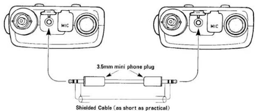
text_image
MIC MIC 3.5mm mini phone plug Shielded Cable (as short as practical)THIS DEVICE COMPLIES WITH PART 15 OF THE FCC RULES. OPERATION IS SUBJECT TO THE CONDITION THAT THIS DEVICE DOES NOT CAUSE HARMFUL INTERFERENCE.
YAESU
VERTEX STANDARD CO., LTD.
4-8-8 Nakameguro, Meguro-Ku, Tokyo 153-8644, Japan
VERTEX STANDARD
US Headquarters
10900 Walker Street, Cypress, CA 90630, U.S.A.
YAESU EUROPE B.V.
P.O. Box 75525, 1118 ZN Schiphol, The Netherlands
YAESU UK LTD.
Unit 12, Sun Valley Business Park, Winnall Close Winchester, Hampshire, SO23 0LB, U.K.
VERTEX STANDARD HK LTD.
Unit 5, 20/F., Seaview Centre, 139-141 Hoi Bun Road, Kwun Tong, Kowloon, Hong Kong
Copyright 2004
VERTEX STANDARD CO., LTD.
All rights reserved
No portion of this manual
may be reproduced without the permission of
VERTEX STANDARD CO., LTD.
Printed in Japan.
