MODE D'EMPLOI PMC 46 HILTI
HILTI
PMC 46
Bedienungsanleitung
de
Operating instructions
en
Mode d'emploi
fr
Istruzioni d'uso
it
Manual de instrucciones
es
Manual de instruções
pt
Gebruiksaanwijzig
n
Obnyiesxnpnoes
el
取級説明書
ja
音歌皂
ko
操作说明书
cn

1
10

16
ORIGINAL OPERATING INSTRUCTIONS
PMC 46 combilaser
It is essential that the operating instructions are read before the tool is operated for the first time.
Always keep these operating instructions together with the tool.
Ensure that the operating instructions are with the tool when it is given to other persons.
| Contents | Page |
| 1. General information | 13 |
| 2. Description | 14 |
| 3. Accessories | 15 |
| 4. Technical data | 16 |
| 5. Safety instructions | 17 |
| 6. Before use | 18 |
| 7. Operation | 18 |
| 8. Care and maintenance | 21 |
| 9. Troubleshooting | 21 |
| 10. Disposal | 22 |
| 11. Manufacturer's warranty | 23 |
| 12. EC declaration of conformity | 23 |
These numbers refer to the corresponding illustrations. The illustrations can be found on the fold-out cover pages. Keep these pages open while studying the operating instructions.
In these operating instructions, the designation "the tool" always refers to the PMC 46 combilaser.
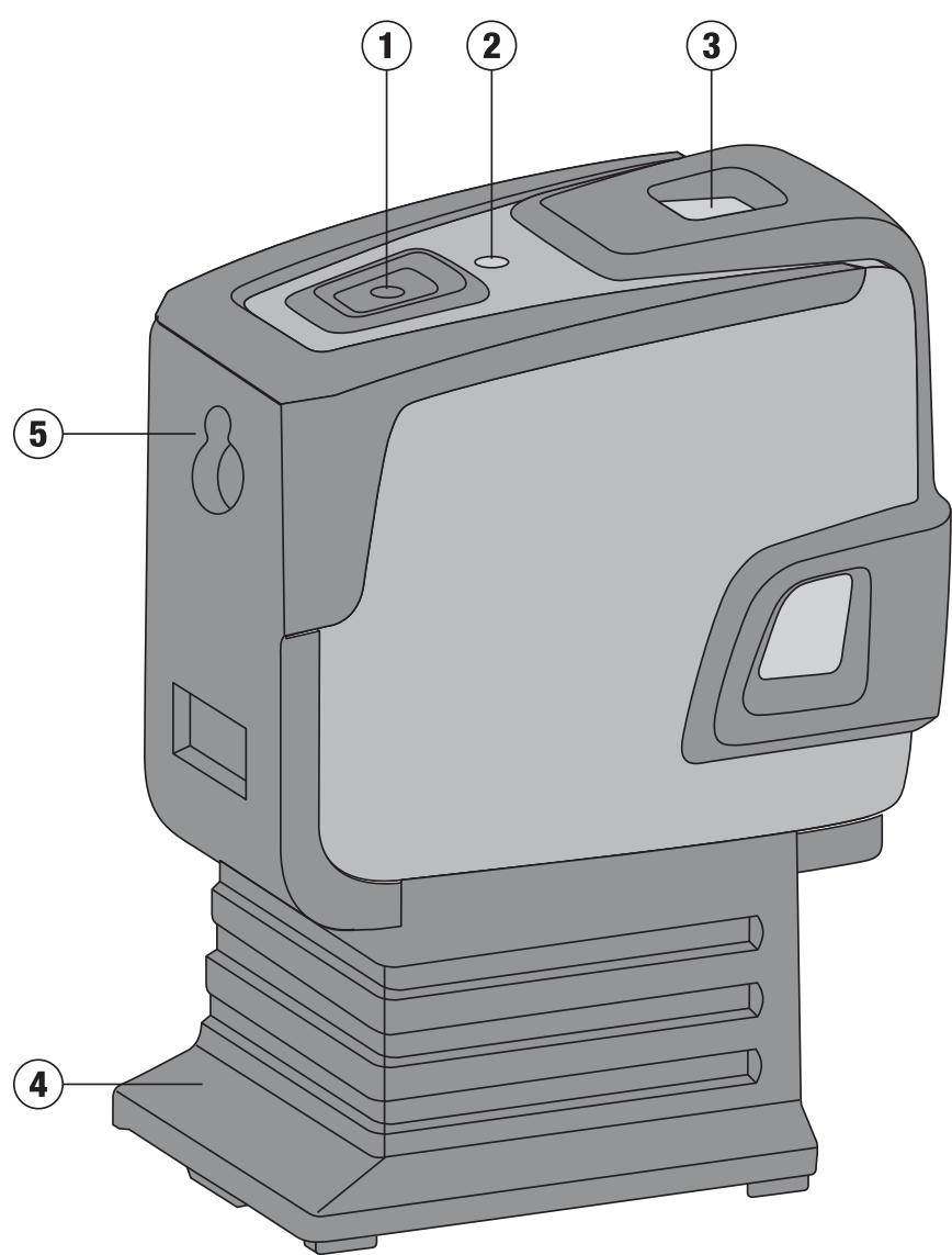
Parts, operating controls and indicators 1
① On-button
② LED
③ Pendulum
④ Removable foot
5 Back of the tool
1.1 Safety notices and their meaning
DANGER
Draws attention to imminent danger that could lead to serious bodily injury or fatality.
WARNING
Draws attention to a potentially dangerous situation that could lead to serious personal injury or fatality.
CAUTION
Draws attention to a potentially dangerous situation that could lead to slight personal injury or damage to the equipment or other property.
NOTE
Draws attention to an instruction or other useful information.
Warning signs

General
warning
Symbols

Read the operating instructions before use.

Disposal of power tools or appliances and batteries together with household waste is not permissible.

Do not stare into the beam.
Laser warning plates for the USA in accordance with CFR 21 § 1040 (FDA).

Laser warning plate in accordance with IEC825 / EN60825-1:2007
The type designation and serial number can be found on the type identification plate on the tool. Make a note of this data in your operating instructions and always refer to it when making an enquiry to your Hilti representative or service department.
Type:
Serial no.:
2.Description
2.1 Use of the product as directed
The PMC 46 is a self-leveling combilaser which allows a single person to level, plumb, align and transfer right angles quickly and accurately. The tool projects two lines (horizontal and vertical) and five points (above, below, right, left and line intersection). The lines and line intersection point have a range of approx. 10m . All other points have a range of approx. 30m . Range depends on the brightness of ambient light.
The tool is designed mainly for indoor use and is no substitute for a rotating laser.
When used for outdoor applications, care must be taken to ensure that the general conditions are similar to those encountered indoors. Possible applications are:
Marking the position of partition walls (at right angles and in the vertical plane).
Aligning components to be installed or sections of a structure in three axes.
Checking and transferring right angles.
Transferring measuring marks from the floor to the ceiling.
Observe the information printed in the operating instructions concerning operation, care and maintenance.
The tool and its ancillary equipment may present hazards when used incorrectly by untrained personnel or when used not as directed.
2.2 Features
The PMC 46 levels itself automatically within a range of approx. 5°
Self-leveling takes only approx. 3 seconds.
The combilaser gives an "Out of self-leveling range" warning when the self-leveling range is exceeded (the laser beams blink).
The PMC 46 is characterized by its ease of operation and use, its rugged plastic casing and ease of transport due to its compact dimensions and light weight.
The tool can be used together with the PMA 31 laser receiver.
In the normal operating mode, the tool switches itself off after 15 minutes. Sustained operating mode can be activated by pressing and holding the on-switch for four seconds.
2.3 Items supplied with the cardboard box version
1 Combilaser
1 Soft pouch
4 Batteries
1 Operating instructions
1 Manufacturer's certificate
1 Combilaser
1 Soft pouch
4 Batteries
1 Operating instructions
1 Universal adapter
1 Manufacturer's certificate
1 Tripod
| LED | The LED doesn't light. | The tool is switched off. |
| The LED doesn't light. | The batteries are exhausted. |
| The LED doesn't light. | The batteries are inserted incorrectly. |
| The LED lights con-stantly. | The laser beam is switched on. The tool is in operation. |
| The LED blinks twice every 10 seconds. | The batteries are almost exhausted. |
| The LED blinks. | The temperature of the tool is above 50°C (122°F) or below -10°C (14°F) (the laser beam does not light). |
| Laser beam | The laser beam blinks twice every 10 seconds. | The batteries are almost exhausted. |
| The laser beam blinks rapidly. | The tool cannot level itself. (outside the 5° self-leveling range). |
| The laser beam blinks every 2 seconds. | The tool is unable to level itself automatically (or is set to "Inclined plane" operating mode). |
3. Accessories
| Tripod | PMA 20 |
| Target plate | PMA 54/55 |
| Target plate | PRA 50/51 |
| Laser receiver | PMA 31 |
| Magnetic bracket | PMA 74 |
| Telescopic brace | PUA 10 |
| Frame clamp | PMA 25 |
| Universal adapter | PMA 78 |
| Hilti toolbox | PMC 46 | |
| Laser visibility glasses | PUA 60 | The laser visibility glasses are not protective glasses and thus do not protect the eyes from laser beams. As the laser visibility glasses restrict color vision, they should be worn only when working with this tool. Do not wear the laser visibility glasses while driving a vehicle on a public road. |
4. Technical data
Right of technical changes reserved.
| Range of the points | 30 m (98 ft) |
| Range of the lines and intersection point | 10 m (30 ft) |
| Accuracy of the points | Distance 10 m (30 ft): ±3 mm (±1/8 in) |
| Accuracy of the laser lines | Length of the lines 10 m (30 ft): ±1.5 mm (±1/16 in) |
| Self-leveling time | 3 s |
| Laser class | Class 2, visible, 635 nm, ±10 nm (EN 60825-3:2007 / IEC 60825 - 3:2007); class II (CFR 21 §1040 (FDA) |
| Beam diameter | Distance 5 m: < 4 mm
Distance 20 m: < 16 mm |
| Line width | Distance 5 m: < 2.2 mm |
| Self-leveling range | ±5° (typical) |
| Automatic power-off | Activated after: 15 min |
| Operating status indicator | LED and laser beams |
| Power supply | AA-size batteries, Alkaline batteries: 4 |
| Battery life (2 points and 1 line) | Alkaline battery 2,500 mAh, Temperature +25°C (+77°F): 20 h (Typical) |
| Operating temperature range | Min. -10°C / Max. +50°C (+14 to 122°F) |
| Storage temperature | Min. -25°C / Max. +63°C (-13 to 145°F) |
| Dust and water spray protection (except battery compartment) | IP 54 as per IEC 529 |
| Tripod thread (tool) | UNC1/4" |
| Tripod thread (foot) | BSW 5/8 "UNC1/4" |
| Weight | with the foot but without batteries: 0.413 kg (0.911 lbs) |
| Dimensions | with the foot: 140 mm X 73 mm X 107 mm
without the foot: 96 mm X 65 mm X 107 mm |
5. Safety instructions
In addition to the information relevant to safety given in each of the sections of these operating instructions, the following points must be strictly observed at all times.
5.1 General safety instructions
a) Check the accuracy of the tool before using it to take measurements.
b) The tool and its ancillary equipment may present hazards when used incorrectly by untrained personnel or when used not as directed.
c) To avoid the risk of injury, use only genuine Hilti accessories and additional equipment.
d) Modification of the tool is not permissible.
e) Observe the information printed in the operating instructions concerning operation, care and maintenance.
f) Do not render safety devices ineffective and do not remove information and warning notices.
g) Keep laser tools out of reach of children.
h) Take the influences of the surrounding area into account. Do not expose the tool to rain or snow and do not use it in damp or wet conditions. Do not use the tool where there is a risk of fire or explosion.
i) Check the condition of the tool before use. If the tool is found to be damaged, have it repaired at a Hilti service center.
j) The user must check the accuracy of the tool after it has been dropped or subjected to other mechanical stresses.
k) When the tool is brought into a warm environment from very cold conditions, or vice-versa, allow it to become acclimatized before use.
If mounting on an adapter, check that the tool is screwed on securely.
m) Keep the laser exit aperture clean to avoid measurement errors.
n) Although the tool is designed for the tough conditions of jobsite use, as with other optical and electronic instruments (e.g. binoculars, spectacles, cameras) it should be treated with care.
0) Although the tool is protected to prevent entry of dampness, it should be wiped dry each time before being put away in its transport container.
p) Check the accuracy of the measurements several times during use of the tool.
5.2 Proper organization of the work area
a) Secure the area in which you are working and take care to avoid directing the beam towards other persons or towards yourself when setting up the tool.
b) Avoid unfavorable body positions when working on ladders or scaffolding. Make sure you work from a safe stance and stay in balance at all times.
c) Measurements taken through panes of glass or other objects may be inaccurate.
d) Ensure that the tool is set up on a steady, level surface (not subject to vibration).
e) Use the tool only within its specified limits.
f) If several laser tools are used in the same working area, care must be taken to avoid confusing the beams.
g) Magnetic fields may affect the accuracy of the tool. It must thus be kept away from magnetic objects. The tool is not affected by the Hilti universal adapter.
h) When working with the receiver, it must be held exactly at right angles to the laser beam.
i) Do not use the tool in the proximity of medical instruments.
5.3 Electromagnetic compatibility
Although the tool complies with the strict requirements of the applicable directives, Hilti cannot entirely rule out the possibility of the tool being subject to interference caused by powerful electromagnetic radiation, leading to incorrect operation. Check the accuracy of the tool by taking measurements by other means when working under such conditions or if you are unsure. Likewise, Hilti cannot rule out the possibility of interference with other devices (e.g. aircraft navigation equipment).
5.4 Laser classification for laser class 2 / class II appliances
Depending on the version purchased, the tool complies with Laser Class 2 in accordance with IEC825-3:2007 / EN60825-3:2007 and Class II in accordance with CFR 21 S 1040 (FDA). This tool may be used without need for further protective measures. The eyelid closure reflex protects the eyes when a person looks into the beam unintentionally for a brief moment. This eyelid closure reflex, however, may be negatively affected by medicines, alcohol or drugs. Nevertheless, as with the sun, one should not look directly into sources of bright light. Do not direct the laser beam toward persons.
5.5 Electrical


a) Insulate or remove the batteries before shipping the tool.
b) To avoid pollution of the environment, the tool must be disposed of in accordance with the cur
rently applicable national regulations. Consult the manufacturer if you are unsure of how to proceed.
c) Keep the batteries out of reach of children.
d) Do not allow the batteries to overheat and do not expose them to fire. The batteries may explode or release toxic substances.
e) Do not charge the batteries.
f) Do not solder the batteries into the tool.
g) Do not discharge the batteries by short circuiting as this may cause them to overheat and present a risk of personal injury (burns).
h) Do not attempt to open the batteries and do not subject them to excessive mechanical stress.
i) Do not use damaged batteries.
j) Do not mix old and new batteries. Do not mix batteries of different makes or types.
5.6 Liquids
Under abusive conditions, liquid may leak from the battery. Avoid contact. If contact accidentally occurs, flush with water. In the event of the liquid coming into contact with the eyes, rinse the eyes with plenty of water and consult a doctor. Liquid ejected from the battery may cause irritation or burns.
6. Before use

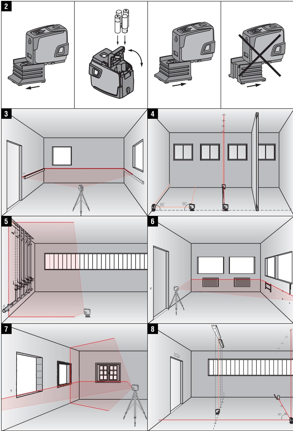
6.1 Inserting the batteries 2
DANGER
Use only new batteries.
-
Remove the foot from the tool.
-
Open the battery compartment.
- Remove the batteries from the packaging and insert them in the tool. NOTE Only batteries recommended by Hilti may be used to power the tool.
- Check that the battery terminals are positioned correctly as shown on the underside of the unit.
- Close the battery compartment cover. Check that the catch engages properly.
- Refit the foot to the tool.
7. Operation

NOTE
To achieve maximum accuracy, project the line onto a vertical, even surface. When doing so, set up the tool at 90° to the surface.
7.1 Operation
7.1.1 Switching the laser beams on
Press the on-button once.
Press and hold the on-button until the laser beam is no longer visible and the LED no longer lights.
NOTE
The tool switches itself off automatically after approx. 15 min.
7.1.3 Deactivating the automatic power-off feature
Press and hold the on-button for approx. 4 sec. until the laser beam blinks three times as confirmation.
NOTE
The tool will be switched off when the on-button is pressed or when the batteries are exhausted.
7.1.4 Inclined line function
- Lay the tool on its back. The tool does not level itself automatically. The tool blinks every two seconds.
For further information, please refer to the PMA 31 operating instructions.
7.2 Examples of applications
7.2.1 Transferring heights 3
7.2.2 Setting out drywall track for a partition wall 4
7.2.3 Aligning pipes vertically 5
7.2.4 Aligning radiators 6
7.2.5 Aligning door and window frames 7
7.2.6 Marking out the position of light fittings 3
7.3 Checking
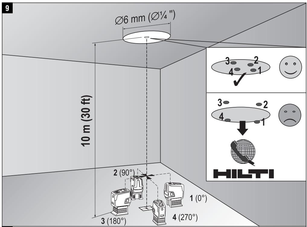
7.3.1 Checking the plumb point 9
- Make a mark on the floor (a cross) in a high room (e.g. in a stairwell or hallway with a height of 5-10 m).
- Place the tool on a smooth, level (horizontal) surface.
- Switch the tool on.
-
Position the tool with the lower beam on the center of the cross.
-
Mark the position of the vertical beam on the ceiling. Attach a piece of paper to the ceiling before making the mark.
- Pivot the tool through 90° .
NOTE The lower plumb beam must remain on the center of the cross.
- Mark the position of the vertical beam on the ceiling.
- Repeat the procedure after pivoting the tool through 180° and 270° .
NOTE The resulting 4 marks form a circle in which the intersection of the diagonals d1 (1 - 3) and d2 (2 - 4) marks the exact center of the plumb point.
9. Calculate the accuracy as described in section 7.3.1.1.
7.3.1.1 Calculation of accuracy
R = 1 0/RH [m] × (d 1 + d 2) [mm]/4 1
R = 3 0/RH [ft] × (d 1 + d 2) [inch]/4 2
The result (R) provided by this formula (RH = room height) refers to the tool's accuracy "in mm at 10m " (formula (1)). This result (R) should be within the specification for the tool (3mm at 10m ).
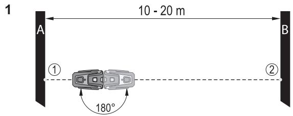
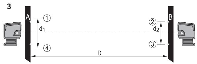
7.3.2 Checking leveling of the forward beam 10
- Place the tool on a smooth, level surface approx. 20 cm from the wall (A) with the laser beam directed toward the wall (A).
- Mark the point of intersection of the laser lines on the wall (A) with a cross.
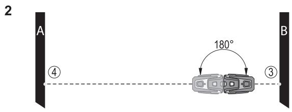
- Pivot the tool through 180° and mark the point of intersection of the laser lines on the opposite wall (B) with a cross.
- Place the tool on an even, level surface approx. 20 cm from the wall (B) with the laser beam directed toward the wall (B).
- Mark the point of intersection of the laser lines on the wall (B) with a cross.
- Pivot the tool through 180° and mark the point of intersection of the laser lines on the opposite wall (A) with a cross.
-
Measure the distances d1 between 1 and 4 and d2 between 2 and 3.
-
Mark the mid points of d1 and d2.
If the reference points 1 and 3 are located on different sides of the mid point, then subtract d2 from d1.
If the reference points 1 and 3 are located on the same side of the mid point, then add d1 and d2 together.
9. Divide the result by twice the length of the room (room length x 2).
The maximum permissible error is 3mm at 10m .
7.3.3 Checking leveling of the lateral beams 10
Repeat the procedure and calculate the accuracy of each of the two perpendicular beams as described at 7.3.2.
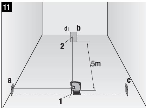
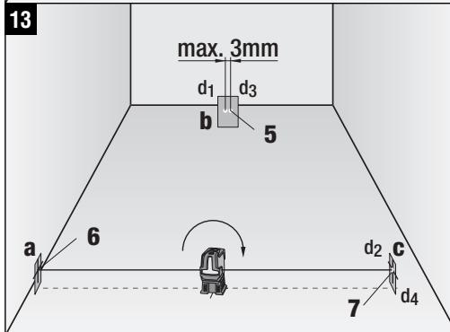
7.3.4 Checking perpendicularity (horizontal) 11 12 13
- Position the tool with the lower plumb beam on the center of a reference cross in the middle of a room at a distance of approx. 5 meters from the walls so that the center of the vertical laser line lies exactly on the vertical line of the first target plate (a).
- Attach a second target plate or sheet of paper (b) to the wall at the half-way position (as shown in the illustration). Mark the mid point (d1) of the right-hand perpendicular beam.
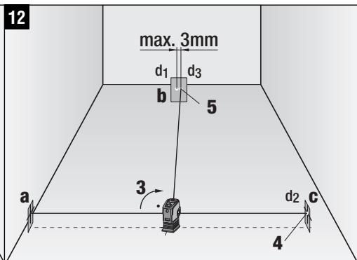
- Pivot the tool clockwise through exactly 90° (as seen from above). The lower plumb beam must remain in the center of the reference cross and the center of the left-hand perpendicular beam must then lie exactly on the vertical line of target plate (a).
- Mark the center point (d2) of the right-hand perpendicular laser beam on target plate (c).
- Mark the mid point (d3) of the point of intersection of the laser lines on target plate (b) or the sheet of paper (from step 7).
NOTE The horizontal distance between d1 and d3 must be no greater than 3mm at a working distance of 5m .
-
Pivot the tool clockwise through exactly 180° (as seen from above). The lower plumb beam must remain in the center of the reference cross and the center of the right-hand perpendicular beam must then lie exactly on the vertical line of target plate (a).
-
Then mark the center point (d2) of the left-hand perpendicular laser beam on target plate (c).
NOTE The horizontal distance between d2 and d4 must be no greater than 3mm at a working distance of 5m .
NOTE If d3 is to the right of d1, the sum of the horizontal distances d1-d3 and d2-d4 must be no greater than 3 mm at a working distance of 5m.
NOTE If d3 is to the left of d1, the difference between the horizontal distances d1-d3 and d2-d4 must be no greater than 3 mm at a working distance of 5m.
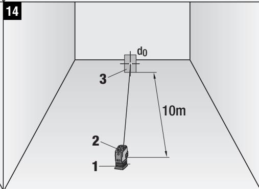
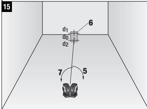
7.3.5 Checking the horizontal lines for curvature 14 15
- Place the tool at the edge of a room with a length of at least 10m
NOTE The floor surface must be smooth and level.
- Switch on all laser beams.
- Set up a target plate at a distance of at least 10m from the tool, so that the point of intersection of the laser lines lies in the center of the target plate (d0) and the vertical line on the target plate runs exactly through the middle of the vertical laser line.
- Mark the mid point of the lower plumb beam on the floor (reference cross).
- Pivot the tool clockwise through 45° (as seen from above). The lower plumb beam must remain on the center of the reference cross.
- Then mark the point (d1) on the target plate where the horizontal laser line strikes the vertical line on the target plate.
- Pivot the tool counterclockwise through 90° . The lower plumb beam must remain on the center of the reference cross.
- Then mark the point (d2) on the target plate where the horizontal laser line strikes the vertical line on the target plate.
- Measure the following vertical distances: d0-d1, d0-d2 and d1-d2.
NOTE The greatest measured vertical distance must be no more than 5mm at a working distance of 10m .
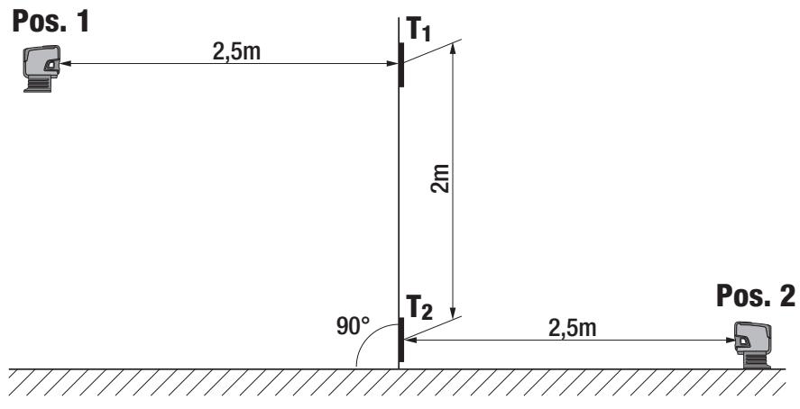
7.3.6 Checking the vertical lines 16
- Position the tool at a height of 2 meters.
- Switch the tool on.
- Position the first target plate T1 (vertical) at a distance of 2.5 meters from the tool at the same height (2 meters), so that the vertical laser beam strikes the plate. Mark this position.
- Then place the second target plate T2 at a position 2 meters below the first target plate, so that the vertical laser beam strikes the plate. Mark this position.
-
Mark position 2 at the opposite side of the test setup (mirror image) on the laser line on the floor at a distance of 5 meters from the tool.
-
Now place the tool on the floor on the mark for position 2 which you have just made. Direct the laser beam toward the target plates T1 and T2 so that it strikes the plates close to their center lines.
- Read the distances D1 and D2 from each target plate (distance of the laser line from the center of the target plate) and calculate the difference (D = D1 - D2)
NOTE Take care to ensure that the target plates are parallel to each other and that they are in the same vertical plane. (Horizontal alignment may result in measurement error).
If the difference D is greater than 3mm the tool must be returned to a Hilti repair center for adjustment.
8. Care and maintenance
8.1 Cleaning and drying
- Blow dust off the glass.
- Do not touch the glass with the fingers.
- Use only a clean, soft cloth for cleaning. If necessary, moisten the cloth slightly with pure alcohol or a little water.
NOTE Do not use any other liquids as these may damage the plastic components.
- Observe the temperature limits when storing your equipment. This is particularly important in winter / summer if the equipment is kept inside a motor vehicle (-25°C to +63°C / -13°F to 145°F)
8.2 Storage
Remove the tool from its case if it has become wet. The tool, its carrying case and accessories should be cleaned and dried (at maximum 63°C / 145°F ). Repack the items only once they have dried completely and then store them in a dry place.
Check the accuracy of the equipment before it is used after a long period of storage or transportation.
Remove the batteries from the tool before storing it for a long period. Leaking batteries may damage the tool.
8.3 Transport
Use the Hilti toolbox or packaging of equivalent quality for transporting or shipping your equipment.
DANGER
Always remove the batteries before shipping the tool.
9. Troubleshooting
| Fault | Possible cause | Remedy |
| The tool can't be switched on. | The battery is exhausted. | Replace the battery. |
| The battery is inserted the wrong way round (incorrect polarity). | Insert the battery correctly. |
| The battery compartment is not closed. | Close the battery compartment. |
| The tool or selector switch is faulty. | If necessary, have the power tool repaired by Hilti Service. |
| Individual laser beams don't function. | The laser source or laser control unit is faulty. | If necessary, have the power tool repaired by Hilti Service. |
| The tool can be switched on but no laser beam is visible. | The laser source or laser control unit is faulty. | If necessary, have the power tool repaired by Hilti Service. |
| The temperature is too high or too low. | Allow the tool to cool down or warm up. |
| Automatic leveling doesn't function. | The tool is set up on an excessively inclined surface. | Set up the tool on the level. |
| The tilt sensor is faulty. | If necessary, have the power tool repaired by Hilti Service. |
10. Disposal
WARNING
Improper disposal of the equipment may have serious consequences:
The burning of plastic components generates toxic fumes which may present a health hazard.
Batteries may explode if damaged or exposed to very high temperatures, causing poisoning, burns, acid burns or environmental pollution.
Careless disposal may permit unauthorized and improper use of the equipment. This may result in serious personal injury, injury to third parties and pollution of the environment.

Most of the materials from which Hilti tools or appliances are manufactured can be recycled. The materials must be correctly separated before they can be recycled. In many countries, Hilti has already made arrangements for taking back old tools or appliances for recycling. Ask Hilti Customer Service or your Hilti representative for further information.

For EC countries only
Disposal of electric appliances together with household waste is not permissible.
In observance of European Directive 2002/96/EC on waste electrical and electronic equipment and its implementation in accordance with national law, electric tools that have reached the end of their life must be collected separately and returned to an environmentally compatible recycling facility.

Dispose of the batteries in accordance with national regulations.
11. Manufacturer's warranty
Hilti warrants that the tool supplied is free of defects in material and workmanship. This warranty is valid so long as the tool is operated and handled correctly, cleaned and serviced properly and in accordance with the Hilti Operating Instructions, and the technical system is maintained. This means that only original Hilti consumables, components and spare parts may be used in the tool.
This warranty provides the free-of-charge repair or replacement of defective parts only over the entire lifespan of the tool. Parts requiring repair or replacement as a result of normal wear and tear are not covered by this warranty.
Additional claims are excluded, unless stringent national rules prohibit such exclusion. In particular, Hilti is not obligated for direct, indirect, incidental or consequential damages, losses or expenses in connection with, or by reason of, the use of, or inability to use the tool for any purpose. Implied warranties of merchantability or fitness for a particular purpose are specifically excluded.
For repair or replacement, send the tool or related parts immediately upon discovery of the defect to the address of the local Hilti marketing organization provided.
This constitutes Hilti's entire obligation with regard to warranty and supersedes all prior or contemporaneous comments and oral or written agreements concerning warranties.
- EC declaration of conformity
Hilti Corporation
| Designation: | Combilaser |
| Type: | PMC 46 |
| Year of design: | 2009 |
We declare, on our sole responsibility, that this product complies with the following directives and standards: 2004/108/EC, 2006/95/EC, EN 55014-1, EN 55014-2, EN 61000-6-3, EN 61000-6-2.

Bodo Baur
Quality Manager
BA Electric Tools & Accessories
03 2009

Tassilo Deinzer
Head BU Measuring Systems
BU Measuring Systems
03 2009
FCC statement / IC statement
-CAUTION
This equipment has been tested and found to comply with the limits for a class B digital device, pursuant to part 15 of the FCC rules. These limits are designed to provide reasonable protection against harmful interference in a residential installation. This equipment generates, uses, and can radiate radiofrequency energy and, if not installed and used in accordance with the instructions, may cause harmful interference to radio communications.
However, there is no guarantee that interference will not occur in a particular installation. If this equipment does cause harmful interference to radio or television reception, which can be determined by turning the equipment on and off, the user is encouraged to try to correct the interference by one or more of the following measures:
- Re-orient or re-locate the receiving antenna.
- Increase the distance between the equipment and receiver.
- Connect the equipment to an outlet on a circuit different from that to which the receiver is connected.
- Consult the dealer or an experienced TV/radio technician for assistance.
-NOTE-
Changes or modifications not expressly approved by the party responsible for compliance could void the user's authority to operate the equipment.
This device complies with part 15 of the FCC Rules.
Operation is subject to the following two conditions:
1) this device may not cause harmful interference, and 2) this device must accept any interference received, including interference that may cause undesired operation.
This device complies with the requirements defined in RSS-210 of IC.
Operation is subject to the following two conditions:
1) this device may not cause harmful interference, and 2) this device must accept any interference received, including interference that may cause undesired operation.
Hilti Corporation
LI-9494 Schaan
Tel.: +423/234 21 11
Fax: +423/234 2965
www.hilti.com