
FT-23R - Émetteur-récepteur radio YAESU - Notice d'utilisation et mode d'emploi gratuit
Retrouvez gratuitement la notice de l'appareil FT-23R YAESU au format PDF.

| Type de produit | Émetteur-récepteur VHF/UHF portable |
| Caractéristiques techniques principales | Fréquences : 144-146 MHz (VHF) et 430-440 MHz (UHF), Mode de modulation : FM, Puissance de sortie : 5W/1W |
| Alimentation électrique | Batterie rechargeable Ni-Cd 7.2V, 600mAh |
| Dimensions approximatives | 120 x 60 x 30 mm |
| Poids | Environ 300 g (avec batterie) |
| Compatibilités | Compatible avec les accessoires Yaesu, y compris antennes et chargeurs |
| Type de batterie | Ni-Cd (Nickel-Cadmium) |
| Tension | 7.2V |
| Puissance | 5W en mode haute puissance, 1W en mode basse puissance |
| Fonctions principales | Scan des fréquences, fonction de verrouillage, réglage de la tonalité, indicateur de batterie faible |
| Entretien et nettoyage | Nettoyer régulièrement avec un chiffon doux, éviter l'exposition à l'eau et à l'humidité |
| Pièces détachées et réparabilité | Pièces disponibles auprès des distributeurs agréés, manuel de service disponible pour la réparation |
| Sécurité | Utiliser uniquement des accessoires recommandés, éviter les environnements extrêmes, respecter les réglementations locales sur l'utilisation des radioémetteurs |
| Informations générales utiles | Vérifier la compatibilité avec les bandes de fréquence locales avant l'achat, idéal pour les amateurs de radio et les situations d'urgence |
FOIRE AUX QUESTIONS - FT-23R YAESU
Questions des utilisateurs sur FT-23R YAESU
0 question sur cet appareil. Repondez a celles que vous connaissez ou posez la votre.
Poser une nouvelle question sur cet appareil
Téléchargez la notice de votre Émetteur-récepteur radio au format PDF gratuitement ! Retrouvez votre notice FT-23R - YAESU et reprennez votre appareil électronique en main. Sur cette page sont publiés tous les documents nécessaires à l'utilisation de votre appareil FT-23R de la marque YAESU.
MODE D'EMPLOI FT-23R YAESU
FT-23R
OPERATING
MANUAL

Copyright © 1990
Yaesu Musen Co., Ltd.
All rights reserved.
No portion of this manual may be reproduced
without the permission of Yaesu Musen Co., Ltd.
Printed in Japan.
YAESU MUSEN CO., LTD.
C.P.O. BOX 1500, TOKYO, JAPAN
YAESU U.S.A.
17210 Edwards Rd., Cerritos, California 90701, U.S.A.
YAESU EUROPE B.V.
Snipweg 3. 1118AA Schiphol, The Netherlands
Contents
Specifications 2
General 2
Receiver 2
Transmitter 2
Accessories & Options List 3
Controls & Connectors 4
Top Panel 4
Side & Front Panels 5
Accessories 7
Battery Packs, Battery Cases & Chargers 7
NC-29 5-hour Quick Charger 7
PA-6 Mobile DC Adapter/Charger for FNB-9, -10, -14 & FNB-17 8
Dry-Cell Battery Cases 8
Battery Removal & Replacement 9
MH-12A2B & MH-18A2B Speaker/Microphones 10
Antenna Considerations 10
Operation 11
Preliminary Operating Information 11
Squelch Setup 11
Transmitting 12
Frequency & Step Selection 13
Memory Storage & Recall 13
Repeater Operation 14
Non-Standard Repeater Splits 15
Scanning 15
Priority Channel Monitoring 16
Tone Squelch Operation 17
In Case Of Problems 18
Getting The Most From Your Batteries 19
Memory Cloning 20
Installation of Options 21
FTS-12 Tone Squelch Unit Installation 21
If FTT-4 is NOT Installed 21
If FTT-4 IS Installed 22
FTT-4DTMFKeypadInstallation 23
Yaesu FT-23R
2m Hand-Held
Cpu-Controlled FM Transceiver
The FT-23R is a compact FM hand-held for the 2-meter amateur band that offers the convenience of very small size and light weight combined with the features and performance flexibility only possible with microprocessor control. A variety of rechargeable battery packs and dry-cell cases are available, providing up to five watts of RF power output.
The transceiver is housed entirely in zinc and aluminum die-cast alloys, and battery cases are constructed of thick high-impact polycarbonate plastic, for professional-grade ruggedness required in the most demanding applications. Rubber gasket seals around all external controls and connectors keep out dust and rain or spray, assuring years of reliable operation even in harsh environments.
Standard microprocessor-controlled features include ten memory channels which each store repeater shifts, CTCSS (Continuous Tone Controlled Squelch System) tone frequencies and tone encode/decode selections; busy channel and priority channel scanning; 1-MHz up/down stepping; plus a top panel rotary dial for memory and frequency selection. Seven of the memories can also be programmed for non-standard repeater shifts. The LCD (Liquid Crystal Display) shows six frequency digits, memory channel selection, and CTCSS tone frequency during tone selection, and includes a bargraph S/PO meter.
The FTT-4 DTMF keypad unit is available as an option, along with a full line of battery chargers, soft cases, and accessories for mobile operation.
Please read this manual carefully to gain a clear understanding of the features of the FT-23R.
Specifications
General
Frequency coverage (MHz): 144 to 147.9995 (versions A, C & E) 144 to 145.9875 (versions B & D)
Channel steps: 5 & 10kHz (vers. A/D/E), 12.5 & 25kHz (vers. B/C)
Standard repeater shift: ±600 kHz
Emission type: G3E
Supply voltage: 6.0 to 15.0 VDC
Current consumption: 19 mA Standby (Save ON); 150 mA Receive; 1500 mA Transmit (5W); 900 mA Transmit (2W)
Antenna (BNC jack): YHA-16 rubber flex antenna
Case size (WHD): 55 × 122 × 32 ~mm with FNB-/FBA-9,
55 × 139 × 32 mm with FNB-/FBA-10
55 × 188 × 32 mm with FNB-11
55 × 155 × 32 mm with FNB-12/-14
55 × 133 × 32 mm with FNB-/FBA-17
Weight (approx): 430g with FNB-10, 550g with FNB-11
Receiver
Circuit type: Double-conversion superheterodyne
Sensitivity: better than 0.25 V for 12 dB SINAD
Adjacent channel selectivity: better than 60 dB
Intermodulation: better than 65 dB
Audio output: 0.4 watts @8 Ω for 5% THD (with 12V supply)
Transmitter
Power output: 5W @12V, 2.5W @7.2V or FBA-10, 2W with FBA-9
Frequency stability: better than 10 ppm
Modulation system: variable reactance
Maximum deviation: ±5 kHz
FM Noise: better than -40dB @ 1kHz
Spurious emissions: better than 60dB below carrier
Audio distortion: less than 5% @ 1 kHz, with ± 3kHz deviation
Microphone type: 2-kΩ condenser
Burst tone: 1750 Hz (except version A)
Specifications may be subject to change without notice or obligation.
Accessories & Options List
FNB-9 7.2-V, 200-mAh Ni-Cd Battery Pack
FNB-10 7.2-V, 600-mAh Ni-Cd Battery Pack
FNB-11 12-V,600-mAh Ni-Cd Battery Pack
FNB-12 12-V,500-mAh Ni-Cd Battery Pack
FNB-14 7.2-V, 1000-mAh Ni-Cd Battery Pack
FNB-17 7.2-V, 600-mAh Compact Ni-Cd Battery Pack
FBA-9 Dry-Cell Battery Case for 6 AAA-size cells
FBA-10 Dry-Cell Battery Case for 6 AA-size cells
FBA-17 Compact Dry-Cell Case for 6 AA-size cells
NC-18B 117-VAC Compact Wall Charger for FNB-11/-12
NC-18C 220—234-V AC Compact Wall Charger for FNB-11/-12
NC-27B 117-VAC Compact Wall Charger for FNB-9
NC-27C 220—234-V AC Compact Wall Charger for FNB-9
NC-28B 117-VAC Compact Wall Charger for FNB-10/-17
NC-28C 220—234-V AC Compact Wall Charger for FNB-10/-17
NC-29 Desktop Quick Charger for all above FNB packs
NC-34B 117-VAC Compact Wall Charger for FNB-14
NC-34C 220—234-V AC Compact Wall Charger for FNB-14
PA-6 Mobile DC Adapter/Charger for 7.2-V packs (FNB-9/-10/-14/-17)
CSC-22 Soft Case for Transceiver with FNB-/FBA-9
CSC-23 Soft Case for Transceiver with FNB-/FBA-10
CSC-24 Soft Case for Transceiver with FNB-11
CSC-25 Soft Case for Transceiver with FTT-4 & FNB-/FBA-10
CSC-26 Soft Case for Transceiver with FTT-4 & FNB-11
CSC-28 Soft Case for Transceiver with FNB-12/-14
CSC-29 Soft Case for Transceiver with FTT-4 & FNB-12/-14
CSC-48 Soft Case for Transceiver with FNB-FBA-17
CSC-49 Soft Case for Transceiver with FTT-4 & FNB-/FBA-17
FTT-4 DTMF Keypad Encoder
MMB-32 Mobile Hanger Bracket
MH-12A2B External Hand Speaker/Microphone
MH-18A2B Miniature External Hand Speaker/Microphone
YHA-16 Rubber flex antenna
FTS-12 CTCSS Subaudible Tone Squelch Unit
Availability of accessories may vary: some accessories are supplied as standard per local requirements, others may be unavailable in some regions. Check with your Yasu dealer for additions to the above list.
Controls & Connectors
Top Panel
(1) EAR Jack
This 2-conductor mini phone jack provides audio output for an external earphone or optional speaker/microphone, while disabling the internal loudspeaker.
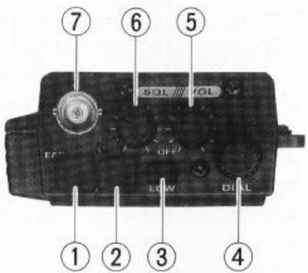
(2) MIC Jack
This 2-contact micro-mini phone jack accepts microphone input from a speaker/-
microphone, or other external source, while disabling the internal microphone.
(3) LOW Power Output Button
Keep this button depressed whenever low power is sufficient for communications. Low power is 200 to 500mW , depending on battery voltage.
(4) DIAL Rotary Selector
This 20-position switch tunes the operating (or CTCSS tone) frequency or selects memory channels, according to the function selected by the front panel keys. This knob duplicates the functions of the and keys for convenience.
(5)VOL/OFFControl
This control adjusts the volume of the receiver. Turn it fully counterclockwise (into the click stop) to turn the transceiver off.
(6) SQL Control
This knob sets the threshold level at which received signals (or noise) open the squelch. For prolonged battery life and squelch sensitivity, set this control just to the point where noise is silenced (and the BUSY/ON AIR lamp on the front panel is off) when the channel is clear.
(7) Antenna Jack
This BNC jack accepts the supplied YHA-16 rubber flex antenna, or any other antenna designed to provide 50-ohm impedance on the 2-meter band.
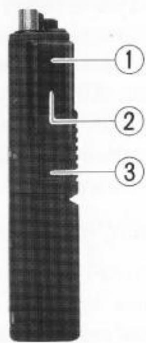
Side & Front Panels
(1) Monitor (Burst) Button
In the US version, this button opens the noise squelch momentarily without disturbing the setting of the SQL control. In the European version, this button activates the 1750-Hz burst tone generator when pressed together with the PTT button.
(2) PTT Button
Press and hold this (Push-to-Talk) button to transmit. The BUSY/ON AIR indicator glows red while transmitting.
(3) Unlock Lever
Slide this mechanical lever upward to release the battery for removal.
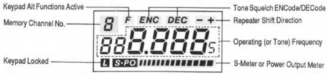
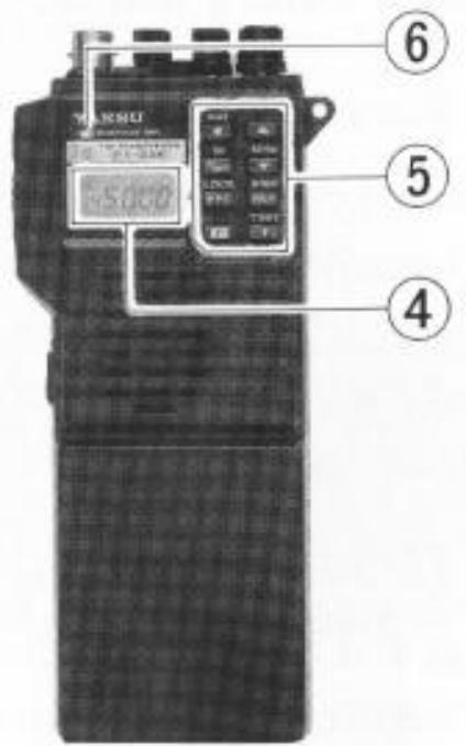
(4) Liquid Crystal Display
The display shows the selected operating conditions as indicated in the following diagram:
(5) Keypad
These eight keys select the various operating features of the transceiver during reception. A beep will sound whenever one of the keys is pressed. The labels on the faces of the keys indicate their primary functions, while the labels above six of the keys indicate alternate functions, which are activated by pressing the F key
first, and then the other key within four seconds. In this manual, we will refer to these functions by the alternate label (above the key), prefixed by “F +” to remind you to press F first. For example, F + ▲ indicates that you should press the F key, followed by the ▲ key within four seconds. All key functions are described in detail in the Operation chapter, and summarized on the FT-23R Operator's Quick Reference Card.
(6) BUSY/ON AIR Indicator Lamp
This LED indicator glows green when the noise squelch is open during reception, and red when transmitting.
Accessories
Battery Packs, Battery Cases & Chargers
The FT-23R requires either the FNB-11 or FNB-12 twelve-volt rechargeable Ni-Cd battery pack for the full 5-watt power output. However, where slightly lower power output (2.5 watts) is practical, the dry-cell battery cases and the FNB-9, FNB-10, FNB-14 and FNB-17 Ni-Cd packs offer smaller size, lighter weight or extended battery charge life. Any of the Ni-Cd packs may be recharged either while attached to the transceiver or separately. Each Ni-Cd pack should be fully charged before it is used with the transceiver for the first time.
Three types of chargers are available: 15-hour compact chargers, the NC-29 1-hour Desktop Quick Charger and the PA-6 Mobile Adapter/Charger.
A different compact charger is required for each model pack:
| Ni-Cd Pack | Voltage | Capacity (mAh) | Compact Charger |
| FNB-9 | 7.2 | 200 | NC-27 |
| FNB-10 | 7.2 | 600 | NC-28 |
| FNB-11 | 12 | 600 | NC-18 |
| FNB-12 | 12 | 500 | NC-18 |
| FNB-14 | 7.2 | 1000 | NC-34 |
| FNB-17 | 7.2 | 600 | NC-28 |
Make certain that you use the correct compact charger for each pack. All of the compact chargers are available with a "B" suffix for operation from 117-VAC mains, or with a "C" suffix for operation from 220 - 234-VAC mains.
NC-29 5-hour Quick Charger
The NC-29 is a universal AC mains battery charger with quick and trickle charging modes for all of the FNB series Ni-Cd packs listed above. It comes wired for the mains voltage in the area sold. The quick mode is automatically selected initially, to bring the battery pack up to full charge as fast as safely possible using an internal timer. Three LED indicators show elapsed charging time after 1, 3 and 5 hours. The charger then reverts to the trickle mode (green indicator), to prevent self-discharge. The quick mode recharges a completely discharged battery in about 5 hours, depending on temperature.
CAUTION
When using the NC-29, do not switch the charger off and on or remove and then replace a battery from the charger while it is charging, as this will reset the timer and may then overcharge the battery.
PA-6 Mobile DC Adapter/Charger for FNB-9, -10, -14 & FNB-17
The PA-6 is a DC-DC adapter for operating the transceiver mobile, and for charging the 7.2-volt FNB-9, FNB-10, FNB-14 and FNB-17 Ni-Cd battery packs. The PA-6 recharges a completely discharged FNB-9 in about 5 hours, an FNB-10/-17 in about 15 hours, or trickle charges an FNB-14 (to full charge in about 35 hours). Be careful to avoid overcharging, as the PA-6 does not include a timer. The PA-6 cannot be used for charging the FNB-11 or FNB-12, as the charging voltage is too low. Use only with 12-volt negative-ground electrical systems.
Dry-Cell Battery Cases
The FBA-9, FBA-10 and FBA-17 dry-cell battery cases may be used with six AAA' (UM-4, for FBA-9) or AA' (UM-3) batteries, but these provide only reduced power, and must not be used with rechargeable cells (because they lack the necessary safety circuits provided in the FNB series).
In some countries, one or more of the above may be supplied with the transceiver. If you need a battery, contact your nearest Yaesu dealer to purchase the desired battery pack or case. We do not recommend the use of any other type of battery with the FT-23R, and using another type may affect your warranty.
CAUTION!
Never allow the terminals of the battery pack or case to be short-circuited!
Battery Removal & Replacement
Make sure that the VOL control is set into the OFF click-stop, and remove the protective soft or hard case, if used.
Grasp the transceiver with your left hand, so your palm is over the speaker and your thumb is on the UNLOCK button.
Move the UNLOCK button in the direction indicated by the arrowhead, while using your right hand to slide the battery

case toward the side with the UNLOCK button. The battery case should slide smoothly out of its track.
To open the FBA-9, FBA-10 and FBA-17 battery cases, place your thumbs on the tracks on top of the case and gently pry the tracks apart. Always replace all six batteries, paying attention to the polarity indicated inside the case.
Do not attempt to open any of the rechargeable Ni-Cd packs.
To replace the battery case or Ni-Cd pack, repeat the second and third steps above, simply sliding the battery case in the other direction after aligning the shorter side of the battery case with the track below the UNLOCK button.
MH-12A2B & MH-18A2B Speaker/Microphones
A Speaker/Mic can increase operating convenience and extend communications range. Each is equipped with a dual plug connector which mates with the EAR and MIC jacks on the top panel of the transceiver, disabling the internal speaker and microphone. The speaker/mic cable allows the transceiver to be left clipped to your belt, or to be held overhead above obstructions for improved performance. Also, using a speaker/mic for mobile operation allows the transceiver to be left in the MMB-32 Mobile Hanger.
Hold the Speaker/Mic close to your ear during reception; or if preferred, connect an earphone to the plug on the Speaker/Mic, attenuating the audio from its loudspeaker. To transmit just hold the Speaker/Mic close to your mouth and close the PTT switch on the microphone.
Antenna Considerations
While the supplied YHA-16 rubber flex antenna is convenient for short-range operation, the standard BNC jack allows for use of a higher gain antenna to extend range in base or mobile operation. Any antenna used with the FT-23R should have an impedance close to 50 ohms on the 2-meter band. If a feedline is used, it should be good quality 50 - coax. Obtaining a proper fit with some BNC plugs may require removing the rubber gasket around the antenna jack on the transceiver.
Operation
This chapter describes the various transceiver functions in detail. After studying these descriptions, keep the FT-23R Operator's Quick Reference Card handy in case you need to refresh your memory.
Preliminary Operating Information
Before operating the transceiver for the first time:
- Charge the battery pack completely (if using Ni-Cd batteries) as described on page 7. If using an FBA series dry-cell battery case, install the batteries as described on page 9.
Connect the YHA-16 rubber flex antenna to the antenna jack on the top of the transceiver. Never operate the transceiver without an antenna connected.
We suggest you do not connect the Speaker/Mic, if you have one, until you are familiar with basic operation.
Before proceeding, please read the Controls & Connectors chapter, if you have not already, to familiarize yourself with the functions of the controls.
When the front panel keys are pressed during reception, a beep will sound. If the keypad beeper begins to sound continuously the battery pack should be recharged or batteries replaced.
Except for certain special cases mentioned later, the keys are disabled during transmission (those on the FTT-4 DTMF keypad, however, only operate during transmission).
If you have trouble getting the transceiver to work as described, see In Case of Problems, on page 18.
Squelch Setup
Set the SQL control fully counterclockwise, rotate the VOL control out of the click-stop and adjust for a comfortable volume on the noise or received signal.
The BUSY/ON AIR indicator LED should glow green, indicating that the squelch is open. If a signal is present, rotate the DIAL selector on the top panel to a channel where only noise is heard.
Adjust the SQL control just to the point where the noise is silenced and the LED is extinguished. (If the SQL control is set further clockwise, sensitivity to weak signals will be reduced.)
Now, whenever a signal reaches the receiver that is strong enough to open the squelch, the BUSY/ON AIR indicator will glow green.
Note that while receiving, one or more bargraph segments may appear along the bottom of the display, indicating signal strength of received signals. This indication is not affected by the squelch setting, so even squelched signals will have some indication. If you notice more than one or two bargraph segments appearing while the squelch is closed, try reducing the squelch control setting (if you want to hear weak signals).
The Monitor switch on the USA versions (just above the PTT switch) allows you to check for channel activity beneath the squelch level and to adjust the volume without having to adjust the squelch: just press the Monitor switch and the noise squelch will open (this does not open the tone squelch, however, if the FTS-12 Tone Squelch option is installed and activated, as described later).
The FT-23R includes an automatic power saver system, which reduces battery consumption by turning the receiver on (for 300 milliseconds) and off (for 600 milliseconds) when the channel is clear and the squelch is closed. The power saver will not affect voice-mode operation,* except to prolong the charge life of your batteries.
Transmitting
Press the LOW button to select low power output. When you wish to transmit, wait until the channel is clear (BUSY/ON AIR LED off), and squeeze the PTT switch on the side of the transceiver while speaking into the microphone (just below the keypad on the front panel). During transmission the BUSY/ON AIR indicator will glow red, and the bargraph will show relative transmitter power output. Release the PTT switch to receive.
If you find that more power is required, set the LOW button to the undexpressed (■) position. However, we recommend that whenever communication is possible with low power, you should keep the LOW button depressed (—) to both conserve battery life and minimize possible interference to other stations.
“Dial” and “Memory” Modes
The FT-23R has two different operating states, referred to as the "Dial mode" and the "Memory mode", which affect the functions of most of the controls. It is important to know which state is currently active when changing frequencies. To determine which state is active, look at the upper left corner of the display. When the Memory mode is active, a Memory number appears. To switch operating states, press the D/MR key.
Frequency & Step Selection
To select a new operating frequency, the transceiver must be in the Dial mode (see box, above). If you see a Memory number, press the D/MR key to switch to Dial mode. There are two ways to select your operating frequency: by the DIAL selector on the top, or with the and keys. For continuous tuning, press and hold the or key for more than 1 / 2 -second. One-Megahertz giant steps are also available: just press F + or F + (and hold the second key for repeated stepping), or press F and rotate the DIAL selector.
Channel steps are 5 or 10kHz in versions A, D and E, and 12.5 or 25kHz in versions B and C. To change from one step size to the other for your version, press F + STEP.* In the 12.5/25-kHz versions a small .5-kHz digit is displayed at the right end of the frequency.
Memory Storage & Recall
The FT-23R offers ten programmable memory channels, numbered 0 through 9. To store a frequency in memory:
Select the desired frequency in the Dial mode as described above,
Press F + M (the Memory number will blink) and select the desired memory number for storage using the DIAL selector or / keys,
Press D/MR to store the Dial frequency into the selected memory: The memory number should disappear, and operation continue in the Dial mode.
Once you press F + M in the above procedure, while the Memory number is blinking, you have a maximum of four seconds between DIAL selections or keystrokes until you press D/MR. If you time out, a memory number will be displayed after you press D/MR (and nothing new will have been stored in the memory). Simply start again. Remember that when you store data in memory, the data previously stored in that channel (if any) is erased.
Example: to store 145.52 MHz in channel 0
Press D/MR once if a Memory number is displayed, to select the Dial mode. Then use the DIAL selector or and keys to select 145.520 on the display.
Press F + M and then rotate the DIAL knob until '0' is displayed (blinking) at the upper left corner.
Press D/MR. There should now be no memory number displayed. If there is, you timed out and should start again.
To recall prestored memories press D/MR, if necessary, to select the Memory mode (memory number displayed), and then rotate the DIAL selector or press the and keys, which select the memories when in the Memory mode (as opposed to frequency selection in the Dial mode). Only prestored memories are displayed: empty memories are skipped.
To exit the Memories and return to Dial mode, press D/MR.
Repeater Operation
Tune to the repeater's output frequency, and then press the RPT key: once for + shift (to transmit 600 kHz above your receive frequency), and again for - shift (to transmit 600 kHz below your receive frequency). Pressing RPT again will return to simplex. A + or - is displayed at the upper right corner when standard repeater shift is selected, and when the PTT switch is pressed to transmit, the
Call Channel Memory 0
Memory 0 is a special 'Call Channel Memory', which can be instantly recalled from any mode just by pressing the key. Press D/MR when finished to return to the previously selected mode.
displayed frequency will shift 600kHz up or down, if in band. If the resulting transmit frequency is outside of the ham band, 'Err' is displayed instead.
You can check the frequency to be used for transmission without pressing the PTT switch: just press REV to reverse transmit and receive frequencies. If two beeps sound and the frequency does not change, the repeater shift is out-of-band. If both frequencies are in band, the shifted frequency will be displayed, and the +' or - at the upper right will blink, signifying that the transmit and receive frequencies are reversed. Using this reverse function allows you to check the repeater input frequency to see if you can work a particular station direct (on a simplex frequency, of course). Press REV again to return to the original repeater shift.
Once standard repeater shift is activated in the Dial mode, it can be stored in any memory along with the frequency (as described in the preceding section). Then whenever that memory is recalled, the stored shift will be active (the +^ or - will be displayed). The reverse function cannot be stored in memory, although both RPT and REV can be pressed to temporarily change repeater operation on a memory that includes repeater shift, the new setting will not be stored. Repeater functions can also be activated temporarily on simplex memories, if required.
Non-Standard Repeater Splits
Memories 0 through 6 can also store an independent transmit frequency, for operation on repeaters with non-standard shift. To do this, first store the receive frequency as described in Memory Storage & Recall. Then retune the Dial to the desired transmit frequency, and repeat the storage procedure, but this time hold the PTT switch at the last step (when you press D/MR the last time while the memory number is blinking). Now when you recall the memory, + - will be displayed together at the upper right. The RPT key will be disabled while operating on the odd-split memory, but the REV key will still function as described above.
Scanning
Before starting the scanner, make sure the SQL control is set to squelch off the noise on a clear channel. As with frequency selection, two different modes of scanning are available: band scanning or memory scanning. In both modes, scanning is manually activated and deactivated by the or key. Just press and hold the key for more than 1/2 -second to start the scanner. If the transceiver is in the Dial mode, band scanning will result. If a memory number is displayed, the transceiver is in the Memory mode, and only prestored memories will be scanned.
The scanner pause son any channel where a signal is found strong enough to open the squelch, and resumes about two seconds after the channel becomes clear. To stop the scanner, press any one of , , D / M R keys or the PTT switch.
For memory scanning, it is sometimes useful to be able to scan only certain memories. To use this feature, you can 'hide' any memory from the scanner (except Memory 0) without erasing it altogether. To hide a memory, press F + D/MR, select the memory to hide, and press F + D/MR again while the memory number is blinking. The display reverts to memory 0, and the hidden memory can no longer be selected or scanned.
To unmask a hidden memory, just repeat the same steps you took to hide it: press F + D/MR, select the memory number to unmask, and press F + D/MR again.
Priority Channel Monitoring
The Priority function allows periodic checking for activity on a "priority channel" while operating on another frequency in the Dial mode, or other memories. When the receiver senses a signal on this priority channel, operation will automatically shift to that frequency, for as long as a carrier is received. If you transmit while the squelch is open on the priority channel, priority monitoring is cancelled and operation stays on the priority channel.
The squelch must first be set so the receiver is silent on a clear channel, and the priority channel frequency must be stored in a memory (this must be Memory 1 if you plan to operate on other memories while priority monitoring). Press D/MR, if necessary, to select the desired Dial or Memory mode, and tune to the frequency or select the memory you want to operate on while priority monitoring. Press F + PRI to activate priority channel monitoring. A 'p' will appear in the memory window at the upper left corner of the display, and about every five seconds the displayed frequency will shift to the priority channel briefly while the receiver checks for a signal.
As long as no signal appears on the priority channel to open the squelch, you can tune, transmit and receive on the Dial, or select and operate on other memories (although the memory number is not displayed). If a station you wish to talk with appears on the priority channel, press the PTT switch momentarily while receiving his signal, to stop priority monitoring on that frequency.
Otherwise, to cancel priority monitoring, press D/MR.
Tone Squelch Operation
The FT-23R can be used to silently monitor for calls on busy channels when the optional FTS-12 Tone Squelch Unit is installed. A general description and installation instructions are on page 21.
To check and optionally set the tone frequency, press F + TSET. The tone frequency will be displayed (in Hz), with a leading zero if that tone selection is a high-Q type. To change the selected tone frequency, rotate the DIAL selector or press ▲ or ▼ until the display shows the tone frequency you require (the display will step through the standard EIA tones, listed in the table below). Press T to return to the operating frequency display when the tone frequency is selected.
To activate the tone squelch functions press the T key. With one press, "ENC" (encode) will be displayed and the tone generator will be activated for transmission. Press T again and both "ENC" and "DEC" (decode) will be displayed together as the tone squelch system is activated for both transmission and reception (only signals sending the matching tone frequency will open the squelch). Pressing T once more disables tone squelch features.
Once you have the tone squelch set up the way you want it, you can store it in memory (or the call channel) by pressing F + M , select the memory to store, and M again. Afterwards, to change a setting stored in memory, just recall the memory, reset the tone frequency or function, and press F + M , and then M alone.
| FTS-12 Tone Frequencies (Hz) | |||
| 67.0 | 100.0 | 141.3 | 203.5 |
| 71.9 | 103.5 | 146.2 | 210.7 |
| 74.4 | 107.2 | 151.4 | 218.1 |
| 77.0 | 110.9 | 156.7 | 225.7 |
| 79.7 | 114.8 | 162.2 | 233.6 |
| 82.5 | 118.8 | 167.9 | 241.8 |
| 85.4 | 123.0 | 173.8 | 250.3 |
| 88.5 | 127.3 | 179.9 | |
| 91.5 | 131.8 | 186.2 | |
| 94.8 | 136.5 | 192.8 | |
In Case Of Problems
FT-23R operation is not complicated, but it is still possible to get lost, at least until you have had the chance to learn the various functions of the keypad and display. If the display shows nothing at all, check the power switch (VOL control), and if necessary, remove the battery pack and check that the contacts are clean. If all appears to be physically in order, recharge or replace the batteries.
Fortunately, the display itself includes enough symbols and function indicators to let you know what is going on as long as power is applied, so it is well worthwhile to study the display diagram on page 5 carefully. For example, if the frequency display changes unexpectedly when you transmit (or if "Err" appears), check for a small "+" or "-" at the upper right-hand corner. Also, if only a few seemingly non-sensical digits appear, press T to disable the tone squelch setting feature.
Attempting an illegal command (such as activating the tone squelch when the FTS-12 is not installed), will cause two beeps to sound. If pressing a key appears to do nothing, first check for a small “L” at the lower left, which indicates if the keypad is locked. If you see this, press F + LOCK to unlock the keys. If the “L” is not there, press D/MR, which will terminate any partially entered commands. If you still cannot enter data, check the ON AIR indicator to see if it is red, indicating that the transceiver is transmitting. Releasing the PTT switch should return the set to receive. If still nothing happens, switch the transceiver off, and then back on.
To avoid confusion resulting from inadvertent key presses, set the keypad lock on (press F + LOCK) if you set the transceiver down while it is on, and then remember to set the lock back off when you wish to enter data.
If none of these measures helps, contact your Yaesu Dealer for assistance.
Getting The Most From Your Batteries
How long the batteries last between charges or replacement depends largely on your operating habits, and how you care for the battery pack (if using a Ni-Cd pack). The FT-23R offers a variety of ways to conserve battery power, and thus to extend the life of each charge. Knowing how to use these features can be critical in emergencies.
Obviously, turning the set off when not in use saves battery life, and can also prevent damage that might result to the batteries if they are over-discharged.
Keeping the receiver squelched automatically activates the power saver function, requiring only about 15% of the power needed when listening to a signal or noise. So when listening for a call, choose a quiet frequency and close the squelch on background noise. The FTS-12 Tone Squelch option is useful for creating your own quiet channel if the entire band is crowded. Also, use the lowest possible volume setting when listening to signals. In noisy environments, use an earphone or the YH-1 headset so you can keep the volume low.
Keeping the LOW power switch on the top panel depressed requires about 60% less current when transmitting, so it is a good idea to develop the habit of always keeping this switch depressed, switching to high power only if low power fails to get through. If you live in a location where high power is almost always needed, consider replacing the antenna with a higher gain type instead of opting for high power (the effect on transmissions is the same). Make sure that any external antenna is designed for 50-ohms impedance at the operating frequency.
As the battery discharges, the voltage drop when transmitting increases. When battery voltage drops to around 6.5V , the beeper will begin to sound continuously, indicating the batteries should be replaced or recharged as soon as possible.
If using rechargeable batteries, do not keep operating once the beeper has come on, as this could cause over-discharge of the cells and destroy the pack. However, recharging Ni-Cd batteries often, with little use in between charges, can also shorten the useful life of the cells. Therefore the best way to get the most out of your Ni-Cds is to use the battery pack just until the beeper comes on, and then immediately give the pack a full recharge. Unfortunately this is not always convenient, since it can be hard to tell exactly when the charge will run out. One solution to this problem is to carry an extra, fully charged pack with you if you do not wish to have operation interrupted.
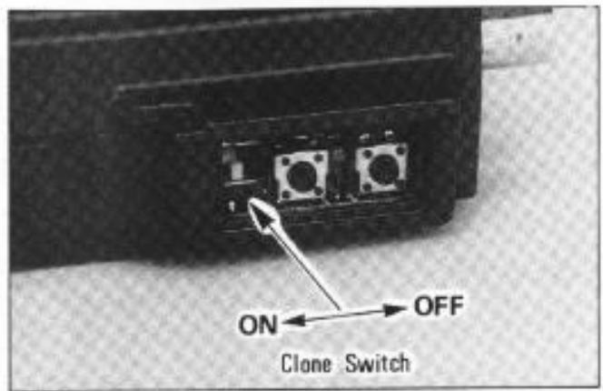
Memory Cloning
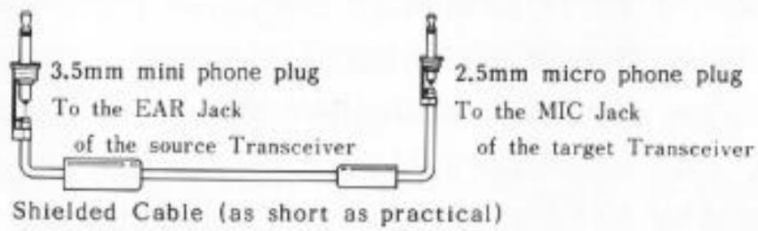
A special function of the FT-23R allows memories stored in one transceiver to be transferred to another set without re-entering data from the keypad. This function requires a user-constructed cable to connect the EAR jack on the source transceiver to the MIC jack on the transceiver to be programmed, and the Clone switch inside the rubber PTT switch cover to be set to ON, as shown below.
Cloning Procedure
Turn the power switch off, and carefully pry out the rubber cover over the PTT switch. Locate the Clone miniature slide switch in the lower part of the opening, and set this switch to its alternate position. Repeat with the other transceiver.
- Connect the EAR jack of the source transceiver to the MIC jack of the target transceiver using a 2-conductor shielded cable.
Turn on the transceivers. All display digits should be blinking.
Press the key on the target transceiver. The display should stop blinking, and remain either on or off (either is acceptable).
Press the key on the source transceiver. The data from Memory 0 in the source transceiver should now appear on the display of the target transceiver, as all other memory data is being transferred. (If not, check your cable.)
If "Err" is displayed on the target transceiver, switch the power off and on, and repeat the last two steps.
After the data has been transferred (a few seconds), turn the radios off, reset the Clone switches to their original positions, and replace the rubber covers.
Installation of Options
FTS-12 Tone Squelch Unit Installation
The FTS-12 is a subaudible CTCSS (Continuous Tone-Controlled Squelch System) which offers programmable selection of 37 tones for transmission and filter/detectors for reception. Transmit-only (encode) and transmit/receive (encode/decode) modes are selectable from keys on the transceiver. Installation is described here, while Tone Squelch operation is described on page 17.
Make sure the transceiver is off. Remove the hard or soft case, if used, and the battery pack as described on page 9. If the FTT-4 DTMF keypad is installed, follow the procedure on the next page. If the FTT-4 is not installed, follow the procedure below instead.
If FTT-4 is not Installed
(1) Remove the four screws affixing the battery spring plate on the bottom of the transceiver and carefully remove the plate.
(2) Locate and remove the small "Dummy Unit" circuit board connected to the 10-pin connector in the compartment on the bottom of the transceiver. It is not needed when the FTS-12 is installed.
(3) Connect the plug in the transceiver to the FTS-12.
(4) Locate the double-sided adhesive tape that is already installed inside the compartment on the bottom of the transceiver, and remove the paper cover from the tape. Then mount the FTS-12 by pressing the flat surface of the IC (on the FTS-12) against the tape (see below).
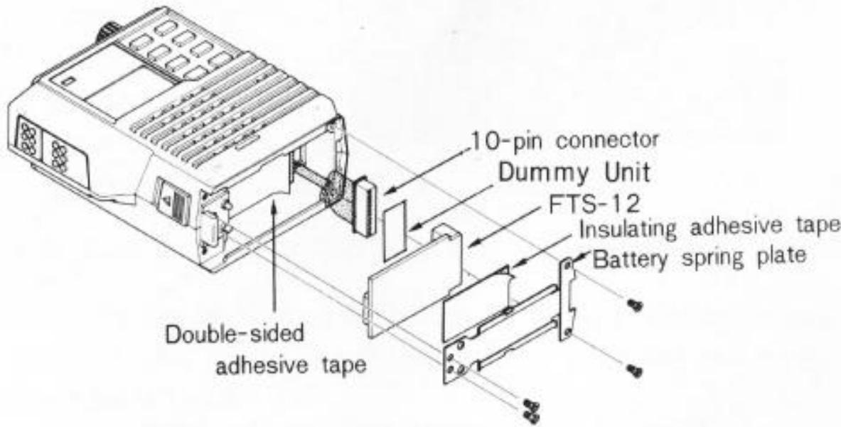
Installing the FTS-12 without the FTT-4
NOTE
If the FTS-12 is later removed, the Dummy Unit must be replaced in the 10-pin connector to allow normal operation.
(5) Apply the (supplied) insulating adhesive tape to the battery spring plate.
(6) Replace the battery spring plate and its four screws, and the battery pack.
If FTT-4 is Installed
(1) Remove the four long screws at the corners on the bottom of the FTT-4. Using care not to stress interconnecting wires, separate the FTT-4 from the transceiver just enough to gain access to the compartment in the bottom of the transceiver.
(2) Perform steps 2, 3 & 4 of the previous procedure. The insulating tape supplied with the FTS-12 is not used when the FTS-12 is installed with the FTT-4.
(3) Replace the FTT-4 and four screws removed in step 1 of this procedure, and then replace the battery pack.
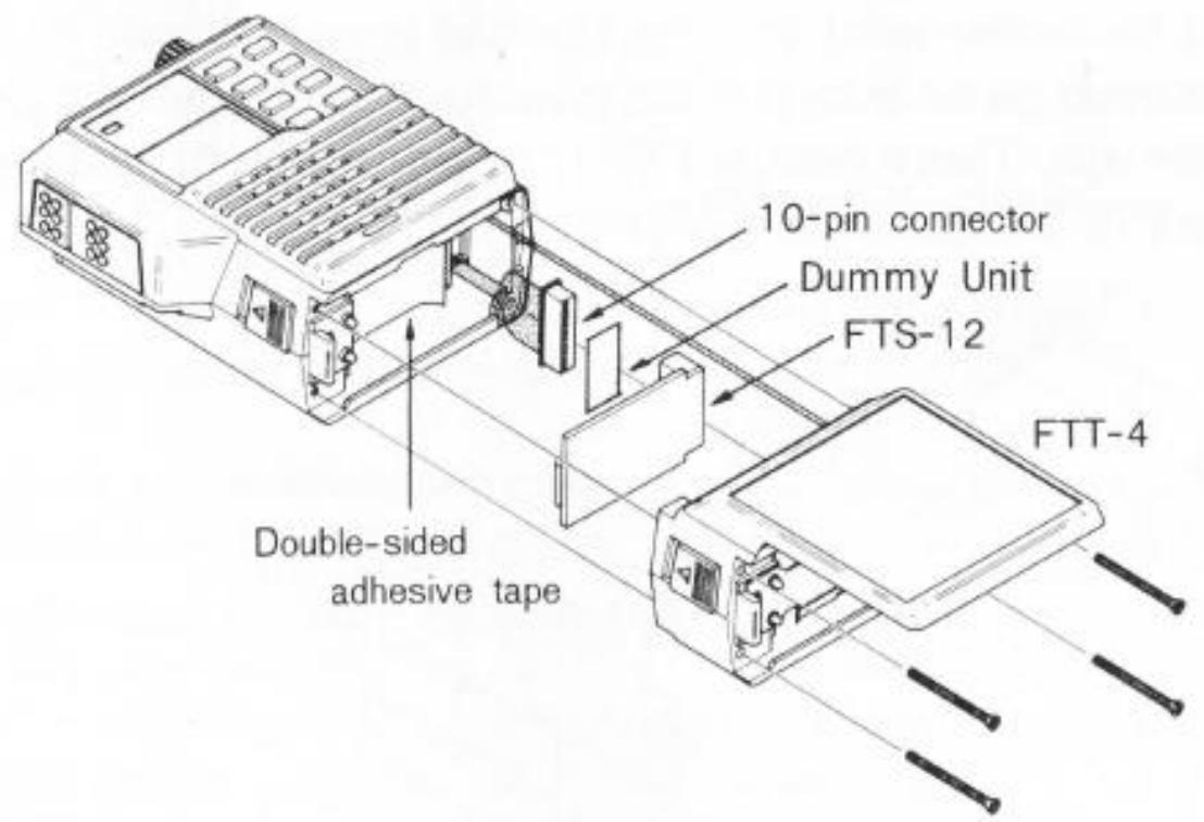
Installing the FTS-12 with the FTT-4
FTT-4DTMFKeypadInstallation
The FTT-4 is a 16-key DTMF (Dual Tone Multi Frequency) keypad which generates EIA-standard DTMF tone pairs when the keys are pressed during transmission (while the PTT switch is held). The audible tones are used for autopatching (remote radio access to the public telephone network), and for remote control of other DTMF-decoder-equipped devices. The FTT-4 may be installed on all versions of the FT-23R (but not with the FBA-/FNB-9, which are too short). Special soft cases are designed for use with the FTT-4; check with your Yasu dealer about availability.
- Make sure the transceiver is off. Remove the hard or soft case, if used, and remove the battery pack as described on page 9.
- Remove the four screws affixing the battery spring plate on the bottom of the transceiver, and remove the plate. These four screws are not used when the FTT-4 is installed.
- Remove the four screws affixing the top panel, and carefully remove the panel.
-
Remove the two screws affixing the front and rear halves of the case, and gently separate the halves, using care not to stress the interconnecting wires.
-
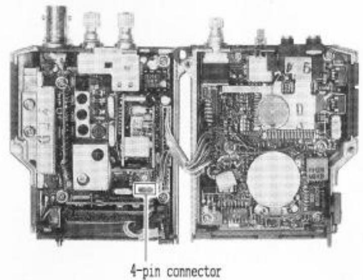
Locate the empty 4-pin connector inside the rear half of the case (as shown in the photo), and route the wire from the FTT-4 through the bottom of the rear half of the case to mate with this connector.
Replace the two screws affixing the front and rear halves of the case, and then the top panel and its four screws.
- Install the battery spring plate on the bottom of the FTT-4 using the two short screws supplied with the FTT-4. These screws go in the two holes close together near the left side.

MEMO :