ISOMAX F 28 E - Chaudière à gaz SAUNIER DUVAL - Notice d'utilisation et mode d'emploi gratuit
Retrouvez gratuitement la notice de l'appareil ISOMAX F 28 E SAUNIER DUVAL au format PDF.
| Type de produit | Chaudière à gaz murale à condensation, modèle ISOMAX F 28 E |
| Marque | SAUNIER DUVAL |
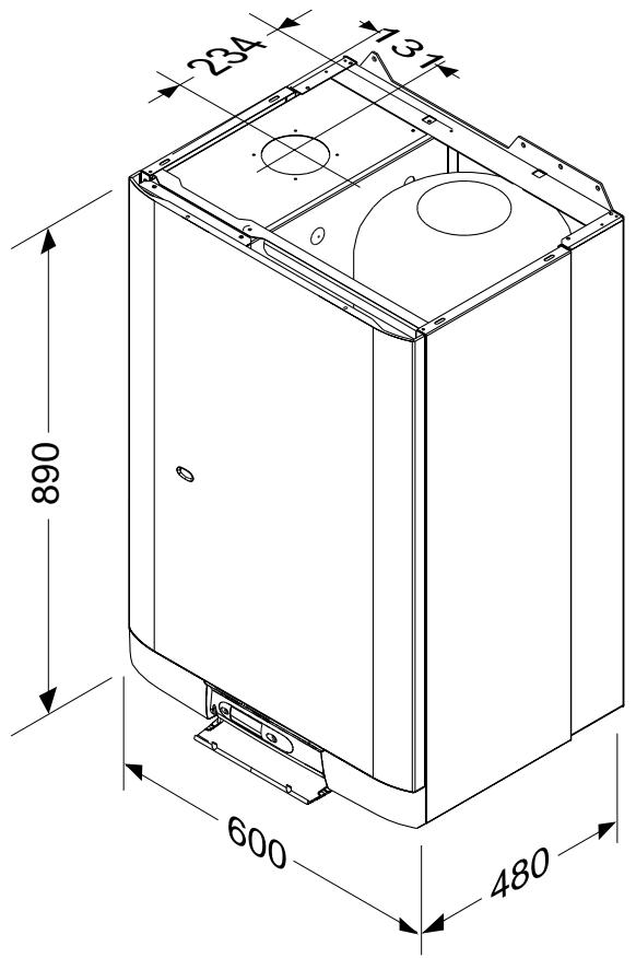
| Dimensions (H x L x P) | 890 x 600 x 480 mm |
| Poids | 71 kg |
| Alimentation électrique | 230 V, 235 W |
| Indice de protection | IP44 |
| Gaz compatibles | Gaz naturel (G20), Butane (G30), Propane (G31) avec kit de conversion |
| Puissance chauffage | 10,4 à 27,6 kW (réglable) |
| Rendement | 91 % |
| Température maximale chauffage | 87 °C |
| Capacité du ballon d'eau chaude | 43 litres |
| Température eau chaude sanitaire | 38 à 60 °C (réglable) |
| Débit spécifique (ΔT 30°C) | 13,2 l/min |
| Pression de fonctionnement min./max. | 0,7 bar / 8 bar |
| Vase d'expansion chauffage | 8 litres, pression de charge 0,5 bar |
| Sécurité | Protection antigel, thermostat de surchauffe (réarmable), sécurité manque d'eau, contrôle de débit d'air, soupapes de sécurité (3 bar, 6 bar, 7 bar) |
| Entretien et nettoyage | Nettoyage de l'habillage avec un chiffon humide ; entretien annuel par un professionnel qualifié |
| Pièces détachées et réparabilité | Thermistors, ventilateur, pressostat, pompe, vanne 3 voies, électrodes, valve à gaz, etc. Liste complète disponible dans la notice |
| Informations générales | Installation par un professionnel qualifié ; respect des réglementations locales ; affichage des codes défaut |
FOIRE AUX QUESTIONS - ISOMAX F 28 E SAUNIER DUVAL
Questions des utilisateurs sur ISOMAX F 28 E SAUNIER DUVAL
0 question sur cet appareil. Repondez a celles que vous connaissez ou posez la votre.
Poser une nouvelle question sur cet appareil
Téléchargez la notice de votre Chaudière à gaz au format PDF gratuitement ! Retrouvez votre notice ISOMAX F 28 E - SAUNIER DUVAL et reprennez votre appareil électronique en main. Sur cette page sont publiés tous les documents nécessaires à l'utilisation de votre appareil ISOMAX F 28 E de la marque SAUNIER DUVAL.
MODE D'EMPLOI ISOMAX F 28 E SAUNIER DUVAL
natural_image
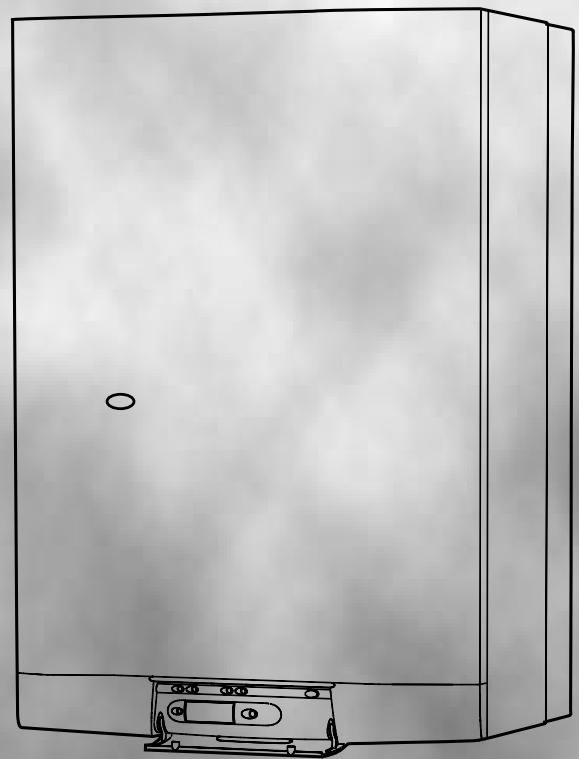
Line drawing of a stainless steel cabinet with a cassette tape attachment (no text or symbols)ISOMAX
CE

THIS IS A CAT I2E+ APPLIANCE
IN WARRANTY
TECHNICAL HELPLINE
01773 828400
HEAT CALL
01773 828100

INSTALLATION AND OPERATING INSTRUCTIONS
ISOMAX F 28 E
Note!
The boiler serial number is marked on the label attached to the inside of the drop down door. Refer to the 'Introduction' section page 3 for a description of the basic functions of the boiler. The 'Users' section describes how to safely operate the boiler.
USERS SECTION
Introduction...... Page 3
Commissioning 3
Controls & lighting 4
Control options .... 5
Draining 5
Servicing/maintenance 5
INSTALLATION SECTION
Introduction...... Page 3
Technical data 6
Dimensions 7
Heating system design 7
Domestic hot water system design.... 8
Boiler schematic 8
Fixing jig 9
Piping system installation 9 - 10
Boiler location 11
Boiler installation 12
Flue installation 12 - 13
Electrical installation 14
Commissioning.... 15 - 18
Safety devices 18 - 19
Settings.... 20
SERVICING SECTION
Routine cleaning and inspection ...... Page 21 - 22
Replacement of parts 22 - 26
Boiler schematic 27
Technical data 28
Schematic wiring diagram 29
Fault finding 30 - 32
Spare parts 32
Mandatory warning for CEE countries
Warning: This appliance is designed, approved and inspected to meet the requirements of the English market. The identification plate located on the inside of the appliance certifies the origin where the product was manufactured and the country for which it is intended.
If you see any exception to this rule, please contact your nearest Saunier Duval dealer.
Thank you in advance for your assistance.
The ISOMAX F boiler is a wall mounted modulating combination boiler with electronic ignition providing central heating and stored hot water.
The boiler is of the I2E+ category for use with Natural Gas (G20) as distributed in the United Kingdom, or Butane (G30), Propane (G31) or Towns Gas (G130) with the appropriate conversion kit.
The boiler has a fan assisted balanced flue which both discharges the products of combustion to and draws the combustion air from the outside of the room.
The boiler is suitable for top outlet flue connection only but, can be fitted with horizontal flue, vertical flue or twin-pipe flue. Refer to flue catalogue for further details.
Both the central heating and domestic hot water temperature are user adjustable from the boiler control panel.
Domestic hot water demand always has priority over heating demand.
The boiler is designed for use as part of a sealed water central heating system with fully pumped circulation. The pump, expansion vessel and associated safety devices are all fitted within the boiler.
The boiler can be installed against either an external wall or on an adjacent inside wall, that is, the flue system will pass directly to the rear or to either side to the terminal fitted on the outside wall face.
The installation must be carried out by a qualified registered person in accordance with the relevant requirements of The Building Regulations, The Water Byelaws, The Building Standards (Scotland) Regulations and any applicable local regulations.
These instructions should be carefully followed for the safe and economical use of your boiler.
Ancillary equipment
A range of flue accessories are available including vertical flues, twin-pipe flues, bends etc. For further information contact your supplier.
Substances Hazardous to Health
The adhesives and sealants used in this appliance are cured and give no known hazard in this state.
INSULATION PADS/CERAMIC FIBRE, GLASSYARN, MINERAL WOOL
These can cause irritation to skin, eyes and the respiratory tract. If you have a history of skin complaints you may be susceptible to irritation. High dust levels are usual only if the material is broken.
Normal handing should not cause discomfort, but follow normal good hygiene and wash your hands before eating, drinking or going to the toilet.
If you do suffer irritation to the eyes or severe irritation to the skin, seek medical attention.
COMMISSIONING
Gas safety (Installation and use) Regulations
In your interests and that of gas safety, it is the law that ALL gas appliances are installed and serviced by a qualified registered person in accordance with the above regulations.
Gas leak or fault
If a gas leak or fault exists or is suspected, turn the boiler off and consult the local gas supply company or your installation/service company.
Air in the heating system
Persistent air in the heating system may indicate leaks in the system or corrosion taking place. Call your Installation/Servicing company.
Overheating safety
In the event of a problem, the overheating safety devices cause safety shutdown of the boiler. If this happens, call your Installation/Servicing company.
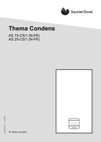
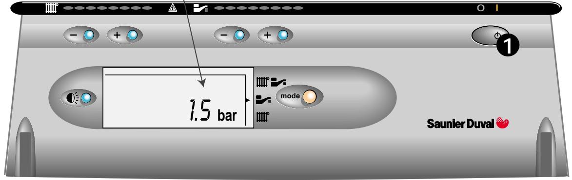
Boiler controls
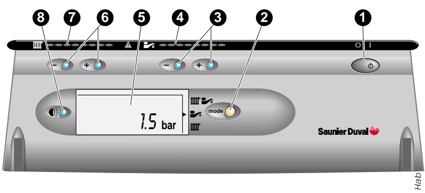
The control panel, located at the lower front of the boiler casing, see diagram 1, allows the boiler to be started, shut down, controlled and monitored during use.
Flue
Do not obstruct the outside terminal of the boiler.
1 - On/Off button
2 - Summer/Winter mode selector
3 - Hot water temperature adjuster
4 - Hot water set point display
5 - Graphic display
6 - Heating temperature adjuster
7 - Heating set point display
8 - Display backlight
Diagram 1
Lighting the boiler :
Make sure that:
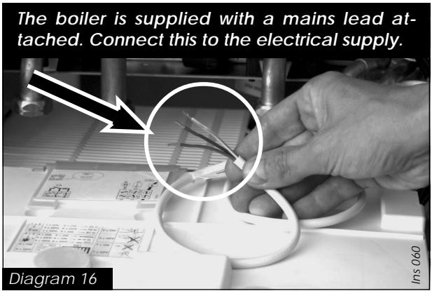
- The boiler is connected to the electrical supply.
- The gas service cock is open.
Then follow the instructions below :

Press the On/Off button (1)
The pressure must be between 1 and 2 bar. If not, the system must be filled by a competent person.
Hab 264
To stop the boiler : Press button (1)
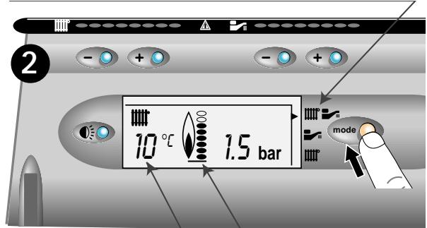
Setting to the SUMMER position (Hot water only)
Press the mode button to select the summer symbol
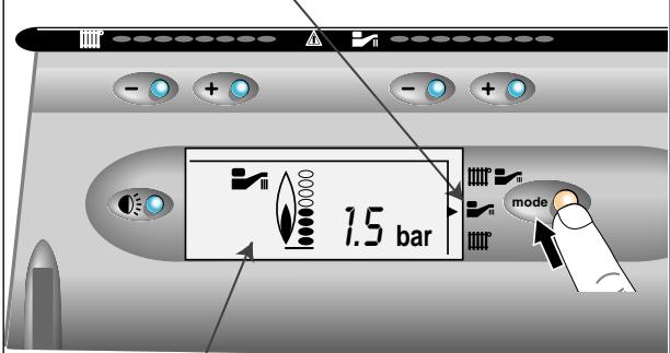
The flame symbol appears when the boiler is running
2
Setting to the WINTER position (Heating + hot water)
Press the mode button to select the winter symbol
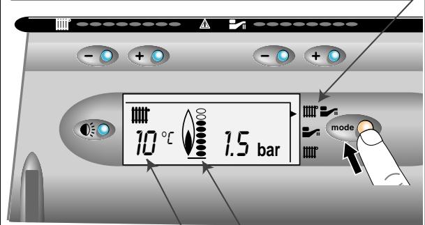
The actual temperature of the heating system
Illuminates when the boiler lights
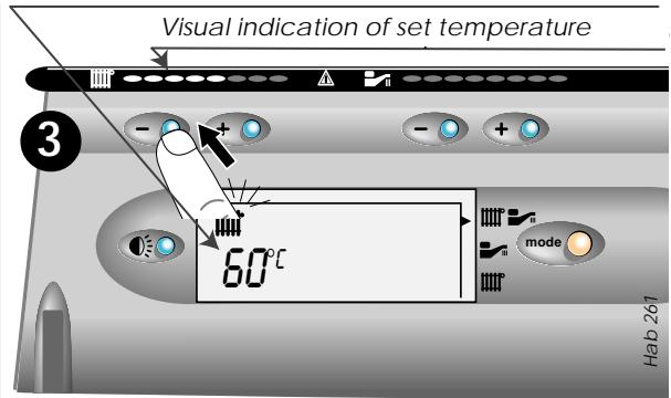
Adjusting the hot water temperature
Press + or - to adjust the maximum temperature of the hot water (38°C to 60°C)
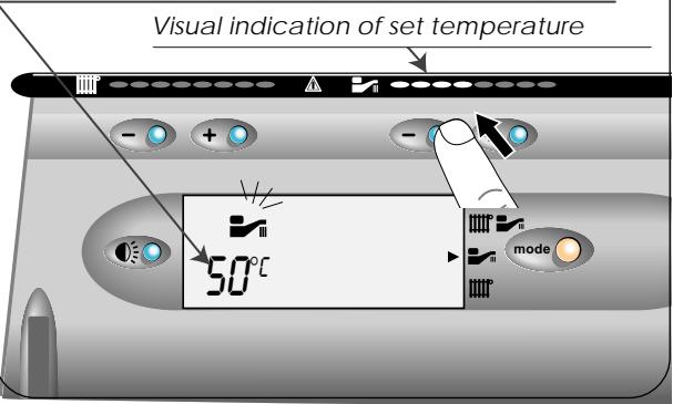
3
Adjusting the heating temperature
Press + or - to adjust the maximum temperature of the heating (38°C to 87°C)
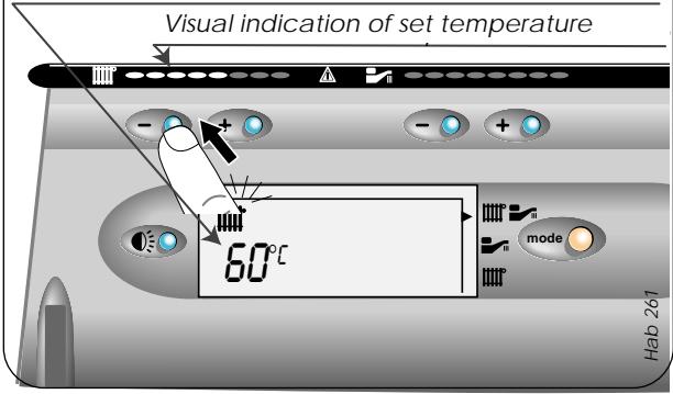
To obtain domestic hot water, open a hot water tap. Hot water always has priority over central heating.
(a) Programmable room stat Part N° 40010,
(b) Isocom combined boiler control & programmable room stat part N° 85915.
ISOCOM

natural_image
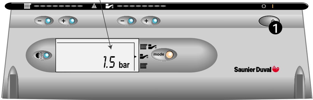
Front view of a Saunier Duval air conditioner unit with digital display and control knobs (no readable text or symbols)Diagram 2
DRAINING
Protection against freezing
If the boiler is to be out of use for any long periods during severe weather conditions, it is recommended that the whole system, including the boiler, be drained to avoid the risk of freezing.
If in doubt, consult your servicing company.
The ISOMAX has a built in frost protection device that protects the boiler from freezing. If the boiler is to be left and there is a risk of frost, ensure that the gas and electrical supplies are left connected. The frost protection device will light the boiler when the temperature of the boiler water falls below 6°C. When the temperature reaches 16°C, the boiler stops.
Note: This device works irrespective of any room thermostat setting and will protect the complete heating system.
SERVICING/MAINTENANCE
To ensure the continued efficient and safe operation of the boiler, it is recommended that it is checked and serviced at regular intervals.
The frequency of servicing will depend upon the installation conditions and usage but, in general, once a year should be enough.
Draining and filling
Caution: The boiler is installed as part of a sealed system which must only be drained and filled by a competent person.
Heating safety valve
CAUTION: A heating safety valve with a discharge pipe is fitted to this boiler.
The valve MUST NOT BE TOUCHED except by a qualified registered person. If the valve discharges at any time, switch the boiler off and isolate it from the electrical supply. Contact your installation/service company.
Pressure/temperature relief valve
CAUTION: A domestic hot water pressure relief valve, with a discharge pipe is fitted to this boiler. The valve MUST NOT BE TOUCHED except by a qualified registered person. If the valve discharges at any time, switch the boiler off and isolate it from the electrical supply. Contact your installation/service company.
Cleaning
The boiler casing can be cleaned with a damp cloth followed by a dry cloth to polish.
Do not use abrasive or solvent cleaners.
Boiler casing
CAUTION. Do not remove or adjust the casing in any way, as incorrect fitting may result in faulty operation. If in doubt, consult your installation/service company.
Heating
| Heating output | adjustable from 10,4 kW to 27,6 kW from 35,484 BTU/H to 94,170 BTU/H |
| Efficiency | 91 % |
| Maximum heating temperature | 87 °C |
| Expansion vessel effective capacity | 8 l |
| Expansion vessel charge pressure | 0,5 bar |
| Maximum system capacity at 75°C | 180 l |
| Safety valve, maximum service pressure | 3 bar |
| Products outlet diameter | 60 mm |
| Fresh air inlet diameter | 100 mm |
Hot water
| Hot water output, automatically variable from 10,4 kW to 27,6 kW from 35,484 BTU/H to 94,170 BTU/H | |
| Storage capacity | 43 l |
| Maximum hot water temperature | 60 °C |
| Minimum hot water temperature | 37°C |
| Specific flow rate (for 30°C temp rise) | 13,2 l/min. |
| Threshold flow rate | 1 l/min. |
| Nominal water flow rate | 11,3 l/min. |
| Temp./pressure relief valve opening pressure | 7 bar |
| Temp./pressure relief valve opening temperature | 90°C |
| Cylinder heat up time | 7 min. |
| Time to reheat 70% of storage to 60°C | 3 min. |
| Expansion valve setting | 6 bar |
| Maximum supply pressure | 8 bar |
| Minimum operating pressure | 0,7 bar |
Electrical
| Electrical supply | 230 V |
| Maximum absorbed power | 235 W |
| Level of protection | IP44 |
Natural Gas (G20)
| Burner injector | 1,20 mm |
| Inlet pressure | 20 mbar |
| Maxi. Burner pressure | 13,8 mbar |
| Mini. Burner pressure | 2,16 mbar |
| Gas rate maximum | 3,20 m^3/h |
| Gas rate minimum | 1,32 m^3/h |
Butane Gas (G30)
| ∅ Burner injector | 0,77 mm |
| Inlet pressure | 29 mbar |
| Maxi. Burner pressure | 23,8 mbar |
| Mini. Burner pressure | 3,6 mbar |
| Gas rate maximum | 2,39 kg/h |
| Gas rate minimum | 0,99 kg/h |
Propane Gas (G31)
| ∅ Burner injector | 0,77 mm |
| Inlet pressure | 37 mbar |
| Maxi. Burner pressure | 30,8 mbar |
| Mini. Burner pressure | 3,6 mbar |
| Gas rate maximum | 2,35 kg/h |
| Gas rate minimum | 0,97 kg/h |
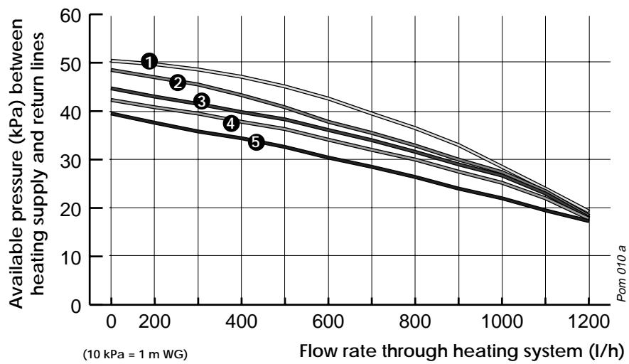
1 Bypass fully shut
② Open 1/4 turn
3 Open 1/2 turn
4 Open 1 turn
5 Open 2 turns

line
| Flow rate through heating system (l/h) | Available pressure (kPa) between heating supply and return lines (l=1 m WG) | | ---------------------------------------- | ---------------------------------------------------------------------------------- | | 200 | 50 | | 400 | 35 | | 1200 | 18 |The ISOMAX is delivered in three separate packages:
- the boiler itself
- the fixing jig
- the flue system
Weight: 71 kg
Hab322
Diagram 5
HEATING SYSTEM DESIGN
- The ISOMAX is compatible with any type of installation.
- Heating surfaces may consist of radiators, convectors or fan assisted convectors.
- The ISOMAX can be piped directly to an under-floor heating system without the need for a mixing bottle. The maximum central heating flow temperature can be set to 53°C on the boiler printed circuit board during commissioning.
- Pipe sectional areas shall be determined in accordance with normal practices, using the output/ pressure curve (diagram 4). The distribution system shall be calculated in accordance with the output requirements of the actual system, not the maximum output of the boiler. However, provision shall be made to ensure sufficient flow so that the temperature difference between the flow and return pipes be less than or equal to 20^ . The minimum flow is 400 l/h.
-
The piping system shall be routed so as to avoid any air pockets and facilitate permanent venting of the installation. Bleed fittings must be provided at every high point of the system and on all radiators.
-
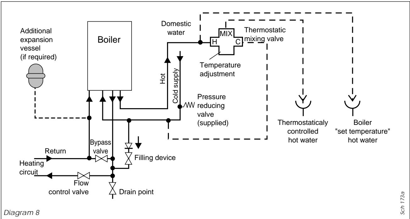
The total volume of water permitted for the heating system depends, amongst other things, on the static head in the cold condition. The expansion vessel on the boiler is pressurised at 0,5 bar (corresponding to a static head of 5 m w.g.) and allows a maximum system volume of 160 litres for an average temperature of 75^ and a maximum service pressure of 3 bar. This pressure setting can be modified at commissioning stage if the static head differs. An additional expansion vessel can be fitted to the system if required, see diagram 8.
- Provision shall be made for a drain valve at the lowest point of the system.
- Where thermostatic radiator valves are fitted, not all radiators must be fitted with this type of valve, and in particular, where the room thermostat is installed.
- In the case of an existing installation, it is ESSENTIAL that the system is thoroughly flushed prior to installing the new boiler.
Filling the system
A filling device must be fitted to the system to initially fill the system and replace water lost during servicing, see diagram 8.
DOMESTIC HOT WATER SYSTEM DESIGN
- Copper tubing or plastic Hep_20 may be used for the domestic hot water system. Unnecessary pressure losses should be avoided.
- A flow restrictor limiting the flow through the boiler to a maximum of 16 l/min is fitted to the boiler.
- The boiler will operate with a minimum supply pressure of 0,7 bar, but under reduced flow rate. Best operating comfort will be obtained from a supply pressure of 1 bar.
'Hard Water Areas'
In areas where the water is 'hard', more than 200mg/litre, it is recommended that a proprietary scale reducer is fitted in the cold water supply to the boiler.
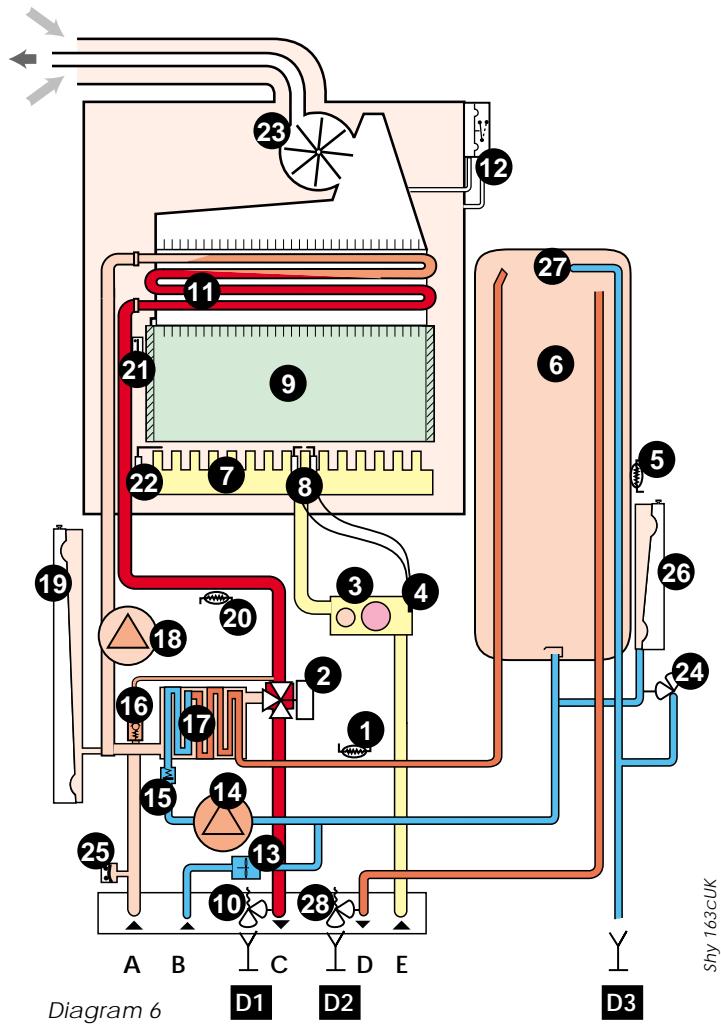
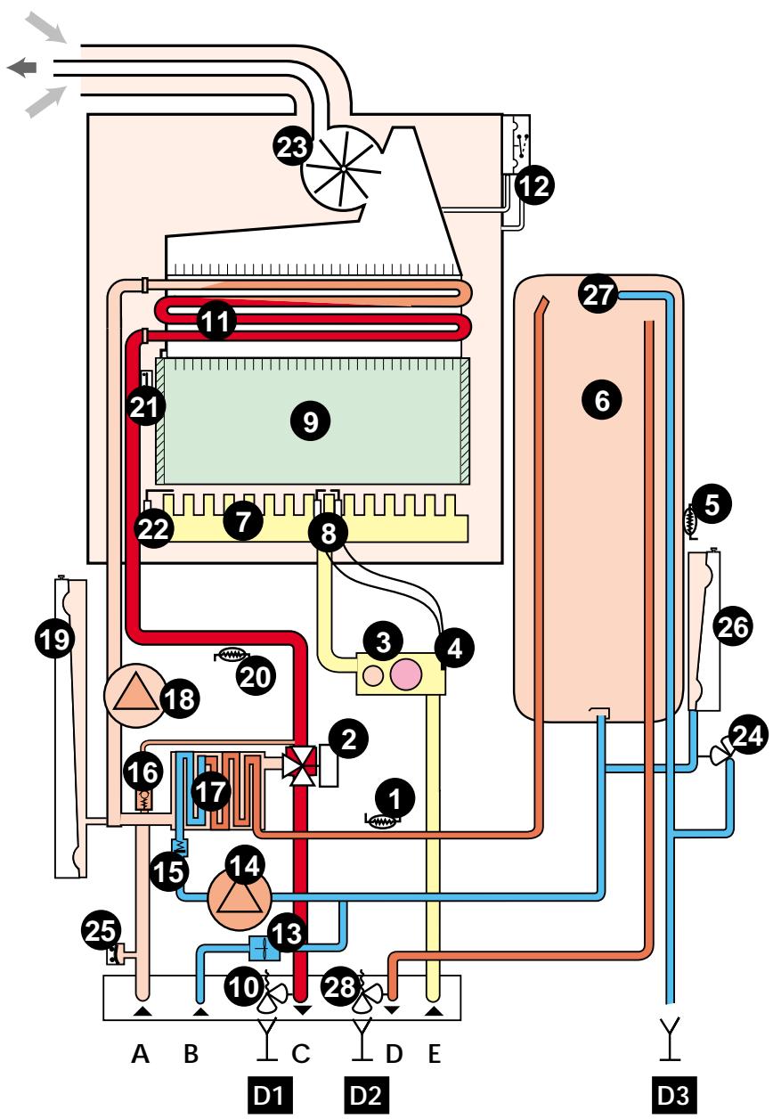
BOILER SCHEMATIC
1 - Domestic thermistor
2 - Three way valve
3 - Gas valve
4 - Gas valve ignition module
5 - Temperatur sensor for accumulation vessel
6 - Accumulation vessel
7 - Burner
8 - Ignition electrode
9 - Combustion chamber
10 - Heating safety valve (3 bar)
11 - Main heat exchanger
12 - Air pressure switch
13 - Flow detector
14 - DHW pump
15 - Non return valve
16 - Bypass
17 - Domestic heat exchanger
18 - Heating pump
19 - Heating expansion vessel
20 - Heating thermistor
21 - Overheat safety thermostat
22 - Flame sensor electrode
23 - Fan
24 - Domestic safety valve (6 bar)
25 - Loss of water sensor
26 - Domestic expansion vessel
27 - Pressure/temperature relief (7 bar)
28 - Domestic safety valve (10 bar)
A - Heating return
B - Cold water inlet
C - Heating flow
D - Domestic hot water outlet
E - Gas
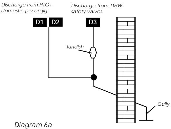
D1 - Discharge from HTG safety valves
D2 - Discharge from DHW safety valves
D3 - Discharge from temp/press (to tundish)
flowchart
graph TD
    A["1"] --> B["2"]
    B --> C["3"]
    C --> D["4"]
    D --> E["5"]
    E --> F["6"]
    F --> G["7"]
    G --> H["8"]
    H --> I["9"]
    I --> J["10"]
    J --> K["11"]
    K --> L["12"]
    L --> M["13"]
    M --> N["14"]
    N --> O["15"]
    O --> P["16"]
    P --> Q["17"]
    Q --> R["18"]
    R --> S["19"]
    S --> T["20"]
    T --> U["21"]
    U --> V["22"]
    V --> W["23"]
    W --> X["24"]
    X --> Y["25"]
    Y --> Z["26"]
    Z --> AA["27"]
    AA --> AB["D3"]
    AB --> AC["D2"]
    AC --> AD["C"]
    AD --> AE["A"]
    AE --> AF["B"]
    AF --> AG["D1"]
    AG --> AH["D2"]
    AH --> AI["E"]
    AI --> AJ["D3"]
| Valve outlet size | Minimum size of discharge to tundish | Minimum size of discharge pipe D2 from tundish | Maximum resistance allowed expressed as a length of straight pipe i.e. no elbows or bends | Resistance created by each elbow or bend |
| G 1/2 | 15 mm | 22mm | up to 9 m | 0.8 m |
| 28 mm | up to 18 m | 1.0 m | ||
| 35 mm | up to 27 m | 1.4 m | ||
| G 3/4 | 22 mm | 28 mm | up to 9 m | 1.0 m |
| 35 mm | up to 18 m | 1.4 m | ||
| 42 mm | up to 27 m | 1.7 m | ||
| G 1 | 28 mm | 35 mm | up to 9 m | 1.4 m |
| 42 mm | up to 18 m | 1.7 m | ||
| 54 mm | up to 27 m | 2.3 m |
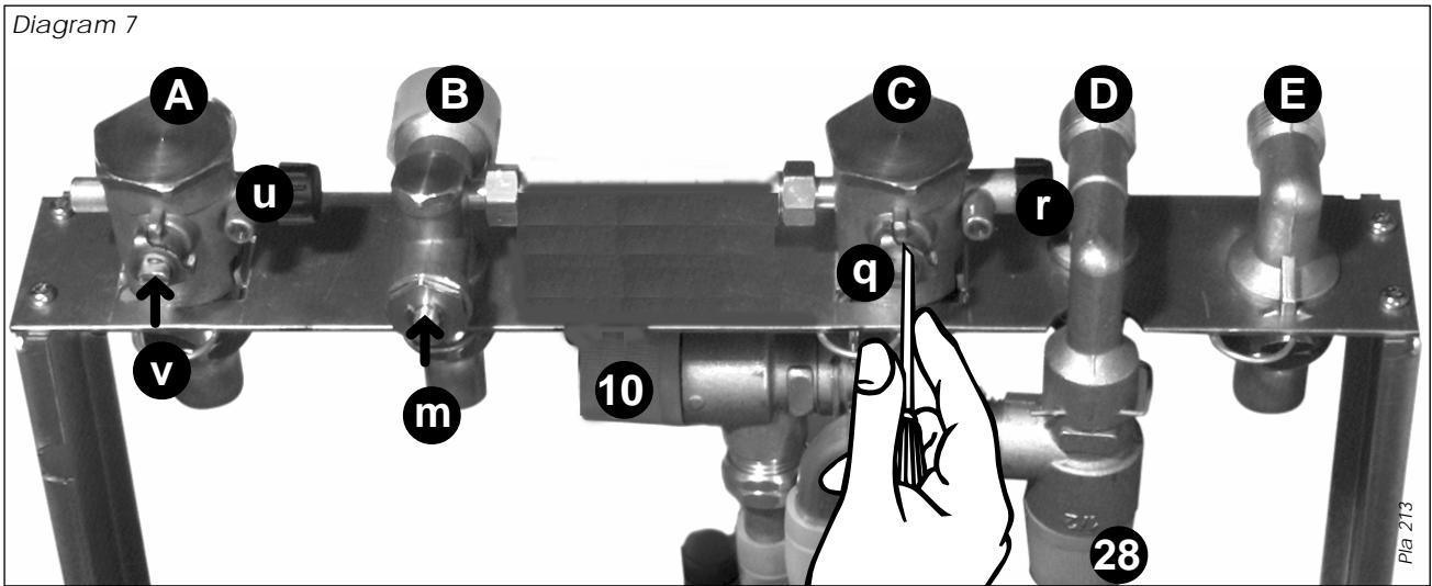
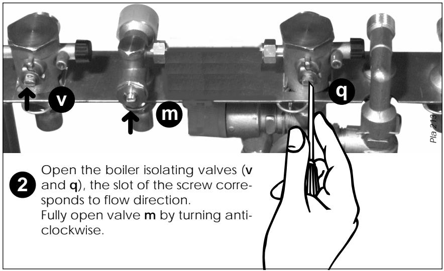
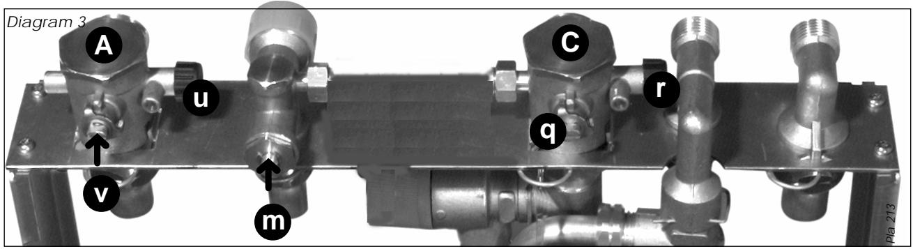
The fixing jig is made up, from left to right, as follows:
A - Heating return fitting with isolating valve(v) and drain knob (u).
B - Cold water inlet fitting with isolating valve (m) and factory fitted flow regulator and filter (not shown).
PIPING SYSTEM INSTALLATION
● Heating system connections - Pipe diam. 22mm
● Hot water system connections - Pipe diam. 15mm
● Gas connection - Pipe diam. 22mm
- Domestic safety valve connection - Pipe diam.15mm
● Heating safety valve connection - Pipe diam. 15mm
Water connection
Connect the copper connections supplied, to the fixing jig fittings, see diagram 7. Connect the sys-
C - Heating flow fitting with isolating valve (q), drain knob (r) and safety valve (10).
D - Domestic hot water outlet fitting with safety valve (28).
E - Gas fitting.
tem pipework to the boiler observing the correct flow and return format as shown in diagram 8. There are two sets of two safety valves fitted to this appliance. Two are located on the jig diagram 7, (10) heating safety valve 3 bar, and (28) DHW safety valve 10 bar. The other two are located inside the boiler (diagram 6,) (27) pressure/temperature relief safety valve 7 bar/90°C, and (24) DHW safety valve 6 bar.
flowchart
graph TD
    A["Additional expansion vessel (if required)"] --> B["Boiler"]
    B --> C["Bypass valve"]
    C --> D["Filling device"]
    D --> E["Drain point"]
    E --> F["Flow control valve"]
    F --> G["Heating circuit"]
    G --> H["Return"]
    H --> I["Hot supply"]
    I --> J["Cold supply"]
    J --> K["Domestic water"]
    K --> L["MIX"]
    L --> M["Thermostatic mixing valve"]
    M --> N["Pressure reducing valve (supplied)"]
    N --> O["W"]
    O --> P["Temperature adjustment"]
    P --> Q["Thermostatically controlled hot water"]
    Q --> R["Boiler "set temperature" hot water"]
    R --> S["Diagram 8"]
Sch 173a
Step. 1
The internal safety valves have been tee'd together and the discharge pipe run so that it exits at the right hand bottom of the boiler (diagram 6) (D2). The tundish (supplied) must be used with this outlet within the normal guidelines and code of practice (diagram 6a).
Step 2
Tee the domestic safety valve (diagram 7) (28) outlet to the heating safety valve (10) outlet together. You can either extend this pipe horizontally to the outside wall. WARNING, It must not discharge above an entrance or window or any type of public access area, the discharge must be extend using no less than 15 mm o.d. pipe to discharge in a visible position outside the building, facing downward preferably over a drain. The pipe must have a continuous fall and be routed to a position so that any discharge of water, possibly steam, cannot create any danger to persons, damage to property or external electrical components and wiring.
alternatively: The discharge pipe can be tee'd into the other discharge pipe after the tundish (diagram 6) provided that it has a continuous fall and that provisions are made for the size of discharge pipe immediately after the tundish (see diagram 6a).
Safety valve discharge
Domestic hot water supply options
Under normal circumstances, the domestic hot water storage temperature inside the boiler can be stored between 37 and 60°C. It is recommended that the boiler storage temperature is set by the user to the maximum of 60°C - this will ensure a more plentiful supply of hot water.
It may be desirable to provide hot water to separate outlets at different temperatures (for example, to provide a limited temperature to prevent the risk of scalding). To be able to do this, a thermostatic mixing valve is supplied with the Isomax boiler (factory set to 43°C) and can be fitted during the installation procedure.
There are 2 options for the domestic hot water supply :
1 - Piping the hot water supply without the use of the mixing valve to provide hot water to all taps at the same temperature.
2 - Piping the hot water supply using the mixing valve (supplied) to provide hot water at boiler hot water "set temperature" to one tap and thermostatically controlled hot water to another tap(s).
To pipe the hot water supply using the mixing valve, refer to diagram 8. This shows one outlet supplying hot water at the boiler hot water "set temperature" and one hot water outlet at a temperature pre-set at the mixing valve. The mixing valve can be set between 35 and 60°C. It is recommended that the valve is adjusted (and locked) by the installer to the desired temperature.
The connections to the mixing valve are :
H - Hot water supply from boiler
C - Reduced cold water supply
MIX - Thermostatically controlled outlet
Warning : It is strongly recommended that the cold water supply to the mixing valve is taken from the reduced side of the pressure reducing valve (supplied)
Note 1 : The mixing valve is fitted with two in-line strainer, one on the hot inlet and one on the cold inlet. For servicing details of these, refer to the separate instructions supplied with the mixing valve.
Note 2 : The mixing valve incorporates a "rapid failsafe" device which will automatically close the valve to safety in the event of supply failure on either hot or cold water.
The discharge must be extended using not less than 22 m o.d. pipe, to discharge in a visible position outside the building, facing downward preferably over a drain.
The pipe must have a continuous fall and be routed to a position so that any discharge of water, possibly boiling or steam, cannot create any danger to persons, damage to property or external electrical components and wiring. Tighten all pipe connection joints.
Gas connection
- The supply from the governed gas meter must be of adequate size to provide a constant inlet working pressure of 20 mbar (8 in w.g.).
To avoid low gas pressure problems, it is recommended that the gas supply is connected using 22 mm pipe. - On completion, the gas installation must be tested using the pressure drop method and purged in accordance with the current issue of BS6891.
Gas Safety (Installation and use) Regulations
In your interests and that of gas safety, it is the law that ALL gas appliances are installed and serviced by a qualified registered person in accordance with the above regulations.
Clearances
The position of the boiler must be such that there is adequate space for servicing.
The recommended clearances are:
20 mm either side of the boiler.
600 mm at the front of the boiler.
300 mm below the boiler.
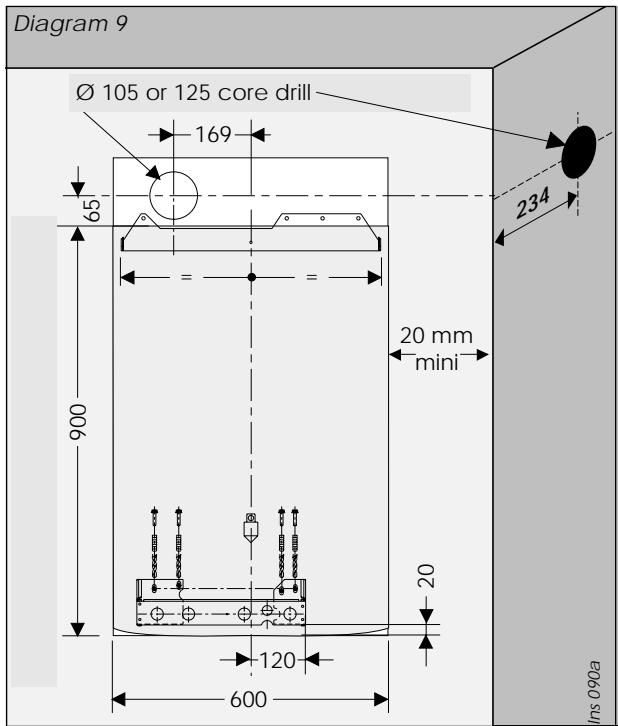
- Place template on wall in required position, making allowances for the necessary clearances etc.
Note: It is permissible to install the boiler with smaller clearances than those quoted above PROVIDING that adequate consideration is given for Servicing/Repairs at a later date. If any doubt exists, contact the Saunier Duval Technical Helpline 01773 828400.
- Mark the position of the holes for the hanging bracket and jig.
- Drill, plug and fix the hanging bracket to the wall using suitable screws.
- Check that the hanging bracket is level.
- Drill plug and fix the fixing jig to the wall.
- For horizontal flue system, mark the position for the flue hole as follows:
Flue to rear of boiler
- Mark correct position of hole from template.
Flue to side of boiler
- Mark the horizontal centre line for the hole on the rear wall. Extend the horizontal centre line to the side wall and mark the vertical centre line of flue hole as shown in diagram 9.
Cutting the flue hole
- Making allowance for the slope of the flue, cut hole in external wall, preferably using a core drill. For installations with internal and external access use a 10.5 mm diameter core drill.
For installations with internal access only use a 125 mm diameter core drill.
Important
When cutting the flue hole and when extending the flue centre line to a side wall, remember that the flue system must have a fall of about 35 mm per metre of flue DOWNWARD towards the terminal. There must NEVER be a downward incline towards the boiler.
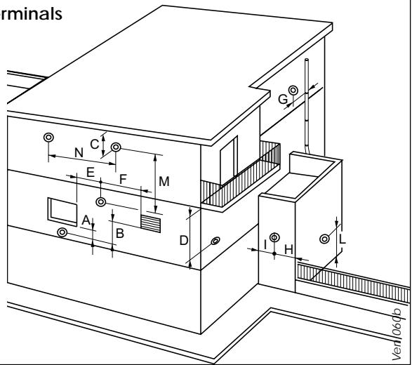
Terminal position
The minimum acceptable spacings from the terminal to obstructions and ventilation openings are shown in diagram 10.
The boiler must be installed so that the terminal is exposed to the external air.
Should any doubt exist as to the permissible position of the terminal, contact the Saunier Duval Technical Helpline 01773 828400.
Terminal guard
If a terminal guard is required, a suitable guard can be obtained from your supplier, Saunier Duval part number 85373.
Cupboard or compartment ventilation
The boiler can be fitted in a cupboard or compartment without the need for permanent ventilation.
Minimum dimensions (in mm) for the positioning of flue terminals
A - Under a window 300
B - Under an air vent 300
C - Under a gutter 75
D - Under a balcony 300
E - From an adjacent window 300
F - From an adjacent air vent 300
G - From vertical or horizontal air pipes 300
H - From an external corner of the building 300
I - From an internal corner of the building 300
L - From the ground or from another floor 300
M - Between two terminals vertically ..... 1500
N - Between two terminals horizontally 600
Statutory requirements
The installation of this boiler must be carried out by a qualified registered person in accordance with the relevant requirements of the current issue of: The Gas Safety (Installation and Use) Regulations The Building Regulations
The local water company Byelaws The Building Standards Regulations (Scotland) The Health and Safety at Work Act
Sheet metal parts
WARNING. When installing or servicing this boiler, care should be taken when handling the edges of sheet metal parts to avoid the possibility of personal injury.
Installing the boiler
Prior to starting work, the system must be thoroughly flushed using a propriety cleanser such as Sentinel X300 to eliminate any foreign matter and contamination e.g. metal filings, solder particles, oil, grease etc.
Note. Solvent products could cause damage to the system.
- Engage boiler upper part onto the hanging bracket.
- Fit the washers between the boiler pipes and the inlet and outlet fittings on the fixing jig and connect the various couplings between the boiler and jig.
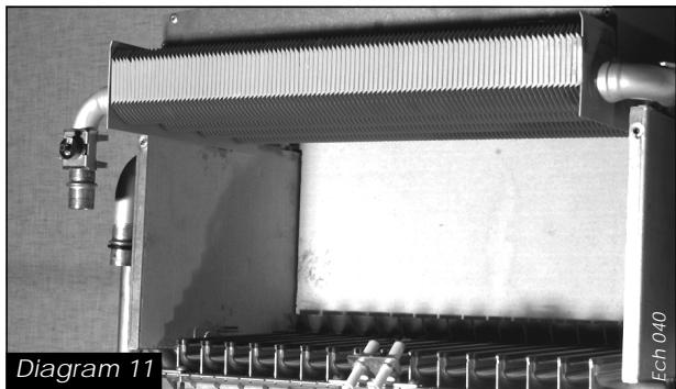
FLUE INSTALLATION
Top outlet flue - kit 85090
The boiler is only suitable for top outlet flue connection.
Rear flue systems
The calculate the lenght when flueing to the rear measure e (diagram 11) plus 25 mm outer flue pipe and e plus 125 mm to inner pipe measurement.
Calculation of cutting lengths when flueing to the right or left
- Measure wall thickness e (mm), see diagram 11.
For right hand applications - Measure distance from inside face of wall to side of the boiler a (diagram 11) add 350~mm to outer pipe measurement and 445~mm to inner pipe mesurement.
For left hand applications
- Measure distance from inside face of wall to side of the boiler a (diagram 11) subtract 25 mm for outer pipe length and add 75 mm to inner pipe length measurement.
- Refer to table 2 for cutting lengths of both inner and outer flue pipes for each of the various flue options available.
Important: All flue cutting lengths must be measured from the terminal end of the flue pipes, see diagram 12.
When the dimension X measured on site is greater than that given in table 2. Extensions will be required as necessary.
Important: All cutting lengths should be measured from the push fit joint end of the extension pipe. Do not leave any burrs or sharp edges on the cut ends of the pipes.
Note : maximum horizontal flue lenght without bends is 3 m.
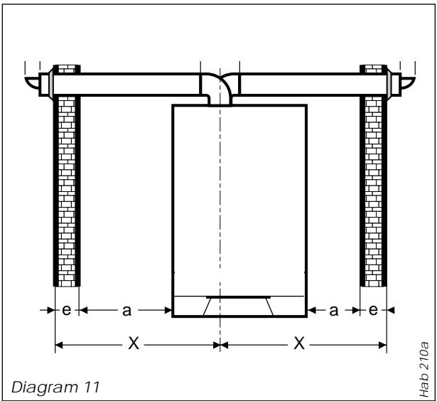
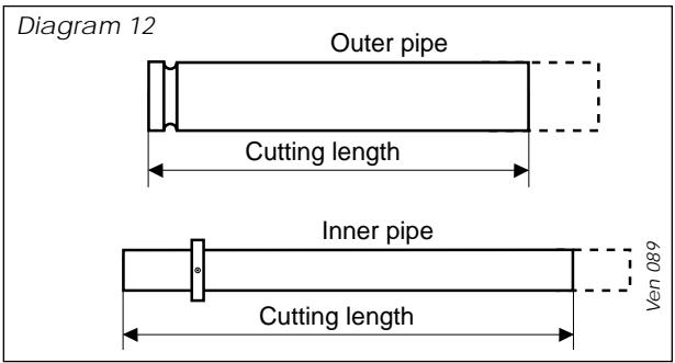
Table 2
Flue cutting lengths (mm)
Rear flue
Outer pipe : e + 25, inner pipe : e + 120
Comment : maximum distance 'x' without extension 770 mm
Right side flue
Outer pipe : e + a + 350, inner pipe : e + a + 450
Comment : maximum distance 'x' without extension 515 mm
Left side flue
Outer pipe : e - 25, inner pipe : e + 125
Comment : maximum distance 'x' without extension 1087 mm
Installation of flue assembly
- Fit rubber sealing collar (F), see diagram 13, into groove at the outer end of pipe (A).
- Fit outer pipe (A) into wall with groove to the outside.
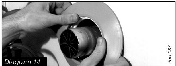
- Pull pipe inwards to bring rubber sealing collar hard up against external wall, see diagram 14.
- Fit internal plastic flange (G) onto outer pipe. Push along the pipe until engaged against internal wall.
- From inside, insert inner pipe (B) into outer pipe.
- Fit both 'O' rings (J) into the flue elbow (C), one at the inlet, one at the outlet. By necessity, they are a loose fit, apply a small amount of silicone grease to each 'O' ring when fitting.
- Wrap sleeve (D) over outer pipe (A) and elbow (C) ensuring it is the correct way round.
- Take hold of the inner flue and push gently onto the elbow outlet taking care not to tear the 'O' ring.
- Open fixing collard (D) and locate between elbow and outer pipe (A). Close fixing jig.
- Engage the two fixing clips (E) onto the colar onto (D) and press down to lock into position. Secure clips with screws provided.
Important: If the flue has been cut, ensure that there are no burrs that could damage the 'O' ring.
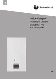
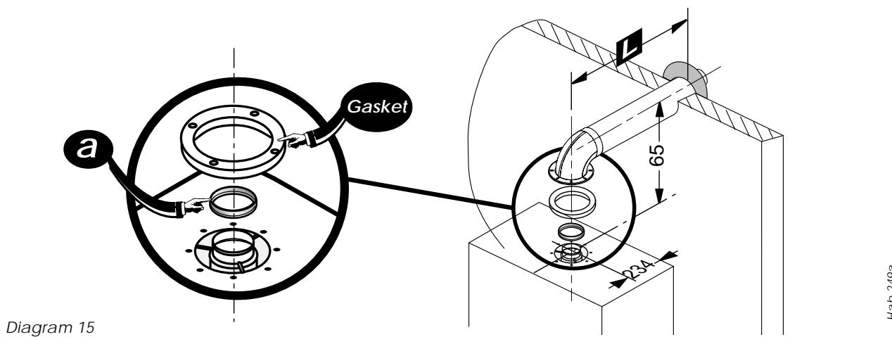
- For flue systems less than 1,5 m long, leave the restrictor (a) fitted in the fan outlet, see diagram 15.
- Remove the backing from the self adhesive gasket (H) and carefully fit gasket to base of flue elbow.
- Fit elbow onto boiler and secure with the four screws (I).
Diagram 13

The flue kit 86285 is 1000 mm long and comprises:
- Outer pipe ...... A
- Inner pipe ...... B
- Flue elbow ...... C
- Fixing collar ...... D
- Locking clips....E
- External rubber sealing collar ...... F
- Internal flange ...... G
- Gasket ...... H
- Screws ....I
- 'O' rings....J
natural_image
Close-up of hands adjusting a mechanical component with a circular opening (no visible text or symbols)Pho 451
Concentric flue system
The maximum permissible length (L) for the concentric flue system is 3 m. For flue systems up to 1,5 m length, the restrictor (a) supplied fitted to the boiler, inside the fan outlet, must be left in place. For longer flue systems, the restrictor must be removed.
For each 90^ flue elbow used, (or two 45^ elbows) the maximum permissible length (L) must be reduced by 1 metre.
Warning. This boiler must be earthed
All system components must be of an approved type.
Connection of the whole electrical system and any heating system controls to the electrical supply must be through a common isolator.
Isolation should preferably be by a double pole switched fused spur box having a minimum contact separation of 3 mm on each pole. The fused spur box should be readily accessible and preferably adjacent to the boiler. It should be identified as to its use.
A fused three pin plug and shuttered socket outlet may be used instead of a fused spur box provided that:
a) They are not used in a room containing a fixed bath or shower.
b) Both the plug and socket comply with the current issue of BS1363.
The mains electrical supply must be maintained at all times in order to provide domestic hot water.
Do not interrupt the mains supply with a time switch or programmer.
WARNING: ON NO ACCOUNT MUST ANY EXTERNAL VOLTAGE BE APPLIED TO ANY OF THE TERMINALS ON THE HEATING CONTROLS CONNECTION PLUG.
Warning: This appliance must be wired in accordance with these instructions. Any fault arising from incorrect wiring cannot be put right under the terms of the Saunier Duval guarantee.
External controls
The ISOMAX boiler is designed to operate at maximum efficiency at all times, but will be most efficient and economical when connected to a room thermostat.
A suitable room thermostat is available as an accessory, Saunier Duval part number 40011. Please contact your supplier.
Also available :
For extra control or if the boiler is to be sited in a garage or utility room an optional remote control unit with programmable roomstat can be obtained part number 85915 (Isocom), diagram 2. This is a dual function unit (a) boiler control (same as boiler facia) (b) programmable room stat. Full fitting instructions supplied with the unit.
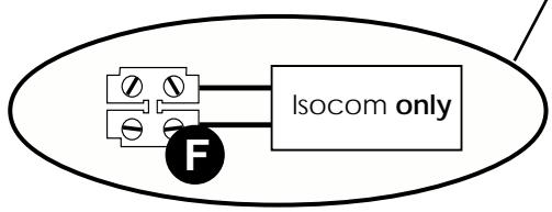
flowchart
graph TD
    A["S"] --> C["Isocom only"]
    B["F"] --> C["Isocom only"]
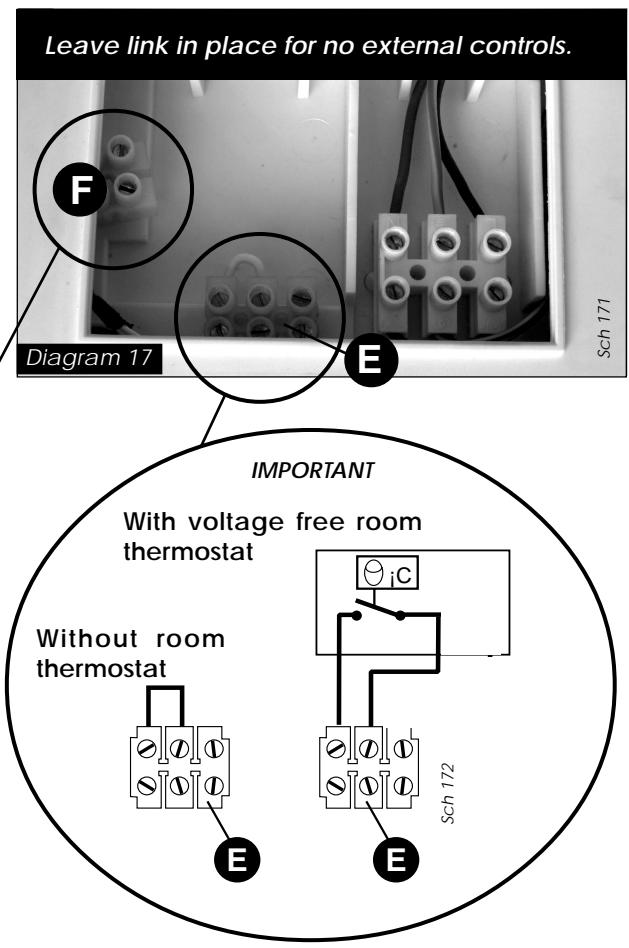
The boiler will work for heating without a room thermostat being connected provided that the wire link fitted between the two terminals of the connector (E) is left in place, see diagram 17.
Alternatively, a 230V room thermostat can be used but do not make any connection to the compensating resistor, see diagram 17.
ON NO ACCOUNT must any electrical voltage be applied to any of the terminals of the external controls plug.
Note: For further information, see the building regulations 1991 - Conservation of Fuel and Power - 1995 edition - appendix G, Table 4b.
The commissioning and first firing of the boiler must only be done by a qualified registered person.
Gas installation
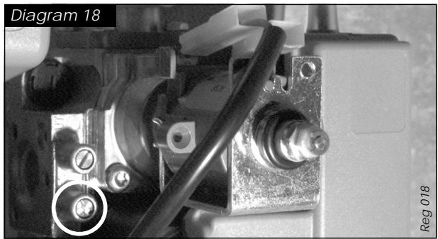
It is recommended that any air is purged from the supply at the gas inlet test point on the gas valve, see diagram 18.
Filling the system
natural_image
Close-up of mechanical components with a black cable and connector, labeled 'Diagram 18' and 'Reg 018' (no readable text or symbols beyond labels)
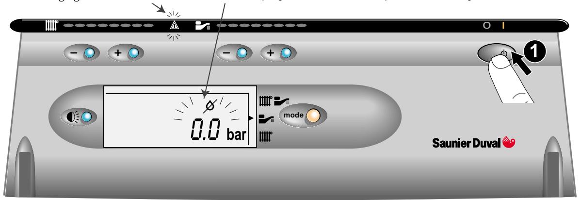
Press the mains 'On/Off' button
The warning light will illuminate
The display will indicate 0 bar pressure in the system
Hab 260

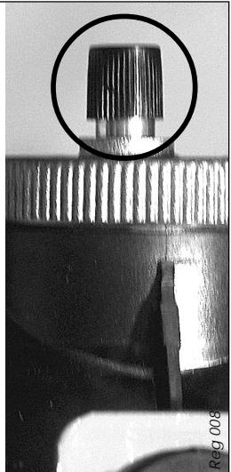
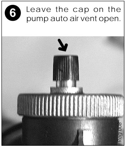
Undo cap on automatic air vent on top of pump and leave undone.
natural_image
Close-up of a mechanical component with a circular inset highlighting a textured top feature (no text or symbols visible)
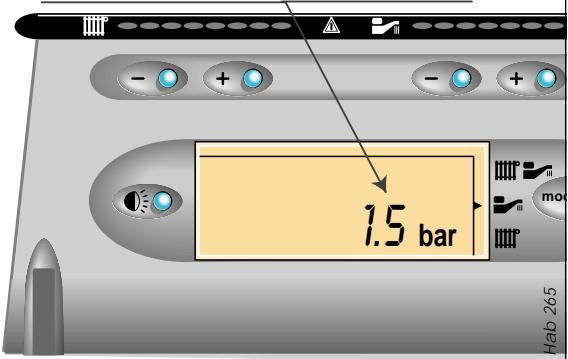
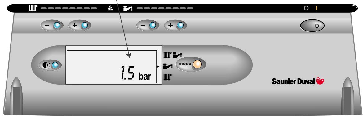
Open filling device fitted previously, fill the system until the pressure indicated on the display is between 1 and 2 bar. Close filling device.
The pressure must be between 1 and 2 bar
8
Make sure the display indicates a system pressure of between 1 and 2 bar. Re-fill system as necessary.
The pressure must be between 1 and 2 bar
Hab 265
Lighting the boiler :
Make sure that:
- The boiler is connected to the electrical supply.
- The gas service cock is open.
Then follow the instructions below :

Press the On/Off button (1)
The pressure must be between 1 and 2 bar. If not, the system must be filled by a competent person.
Hab 264
To stop the boiler : Press button (1)
Setting to the WINTER position (Heating + hot water)
Press the mode button to select the winter symbol
The actual temperature of the heating system
Illuminates when
the boiler lights
Adjusting the heating temperature
Press + or - to adjust the maximum temperature of the heating (38°C to 87°C)
- Adjust heating temperature to maximum.
- Check that any external controls, if fitted, are calling for heat (set room thermostat to maximum).
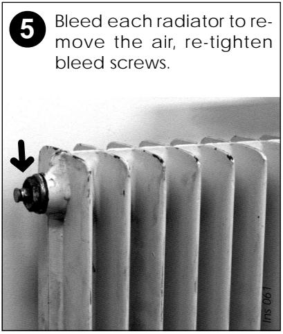
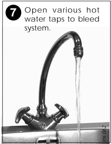
- Allow the temperature to rise to the maximum value, with all radiator valves open. The temperature rise will cause release of the gases contained in the water of the central heating system.
● Gases driven towards the boiler will be automatically released through the automatic air vent.
● The gases trapped at the highest point of the system must be released by bleeding the radiators.
On reaching maximum temperature, the boiler should be turned off and the system drained as rapidly as possible whilst still hot.
- Refill system to a pressure of between 1 and 2 bar and vent as before.
- Restart boiler and operate until a maximum temperature is reached. Shut down boiler and vent heating system. If necessary, top up heating system and make sure that a pressure of at least 1 bar is indicated when system is COLD.
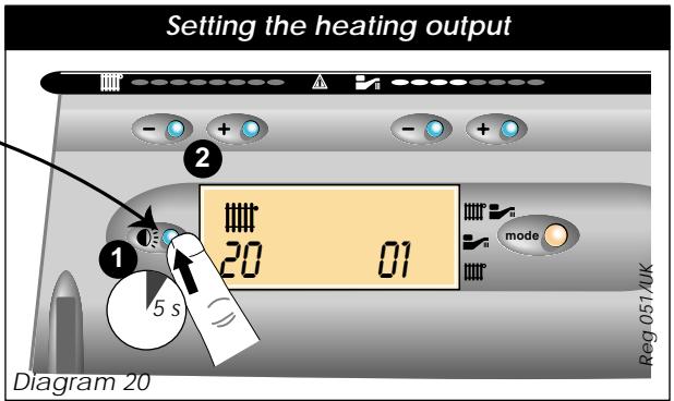
Setting the heating output
The heating output can be set without the use of a pressure gauge; proceed as follows:
- Press the display light button and keep pressed for 5 seconds, see diagram 20.
Note: The boiler has now been put into 'Service Mode', allowing certain adjustments to be made and diagnostic fault codes to be displayed. Refer to the 'Servicing Instructions' for further details.
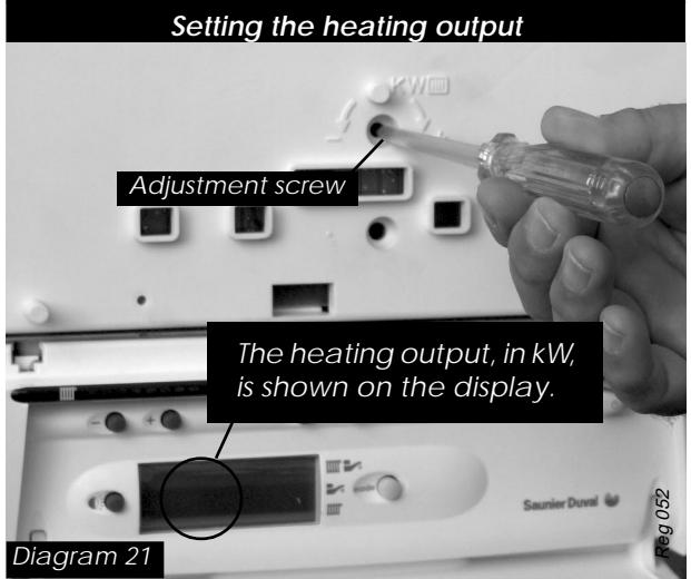
The heating output, in kW, is shown on the left hand side of the display, see diagram 21.
- Remove the blanking plug from the front of the control panel to gain access to the heating adjusting screw.
- Adjust the heating output by turning the screw clockwise to increase, anti-clockwise to decrease.
- Refit blanking plug.
Note: Adjustment of the heating output does not affect the domestic hot water output.
For kW to Btu/hr conversion refer to table 5.
Table 5 kW to Btu/hr conversion
| kW | Btu/hr |
| 10 | 34,120 |
| 12 | 40,940 |
| 14 | 47,770 |
| 16 | 54,590 |
| 18 | 61,420 |
| kW | Btu/hr |
| 20 | 68,240 |
| 22 | 75,060 |
| 24 | 81,890 |
| 26 | 88,710 |
| 28 | 95,540 |
| kW | Btu/hr |
| 30 | 102,360 |
| 32 | 109,180 |
| 34 | 116,000 |
| 35 | 119,420 |
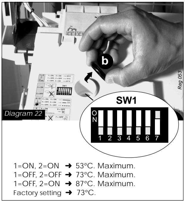
Setting the maximum heating temperature
The maximum heating temperature can be preset at commissioning stage to suit the type of heating system.
For example, for use with underfloor heating, the maximum heating temperature can be set to 53^ C. To adjust the maximum temperature, proceed as follows:
- Remove the blanking plug (b) from the rear of the control panel to gain access to selector switch SW1 (see diagram 22).
Adjust toggles 1 and 2 to give the desired maximum heating temperature, see diagram
Note: To adjust the maximum heating temperature it is only necessary to change toggles 1 and 2. Do NOT touch any other toggles.
- Refit blanking plug.
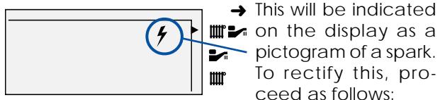
SAFETY DEVICES
The ISOMAX incorporates a visual display that indicates fault conditions, should they occur.
In the event of a fault, the display will indicate, by means of pictograms and/or letters and numbers, exactly in which area the fault lies.
Should the boiler fail to operate during Commissioning, the most likely fault is that the gas supply to the boiler has not been turned on or purged sufficiently or that there is no pressure in the heating system. These are indicated as follows:
No gas supply
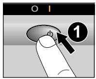
- Switch off the boiler at the On/Off push button.
- Rectify the gas supply problem.
- Restart the boiler by pressing the On/Off button.
Insufficient system pressure
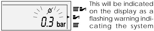
To rectify this the system must be re-filled, refer to 'Commissioning'.
Other faults
These are indicated on the display by a fault code and a telephone symbol. Further information on the fault codes can be found in the 'Servicing Instructions'.
General safety devices
Air flow rate safety device
If an obstruction, even partial, of the flue occurs, for any reason whatsoever, the built in safety system of the boiler will turn the boiler OFF and the fan will continue to run.
The boiler will be ready to operate when the fault has been cleared.
Overheat safety
In case of boiler overheating, the overheat thermostat will turn the boiler off. The thermostat, located on the heat exchanger flow pipe, will need to be manually reset.
In case of power supply failure
The boiler no longer operates.
As soon as power supply is restored, the boiler will be automatically restarted.
Frost protection
The ISOMAX has a built in frost protection device that protects the boiler from freezing. If the boiler is to be left and there is a risk of frost, ensure that the gas and electrical supplies are left connected. The frost protection device will light the boiler when the temperature of the boiler water falls below 6^ C. When the temperature reaches 16^ C, the boiler stops.
Note : This device works irrespective of any room thermostat setting and will protect the complete heating system.
CHANGING GAS TYPE
Should it become necessary to change the gas type, a modification kit will be required.
This modification must only be carried out by a suitably qualified engineer.
Conversion natural Gas (G20) to G30/G31 Part No. 86216.
Gas valve setting
All boilers are tested and factory set during manufacture. Should it be necessary to reset a gas valve, for example, after replacement, proceed as follows:
- Shut down boiler.
Minimum setting
- Remove one electrical connector from the modulating gas valve coil, see diagram 23.
- Connect a suitable pressure gauge.
- Set the OFF/Summer/Winter switch to the 'Summer' position.
- Adjust the domestic hot water temperature adjuster to maximum setting.
- Remove the protective cover from the gas valve adjuster.
- Turn nut 'A', see diagram 23:
CLOCKWISE: To increase the pressure.
ANTICLOCKWISE: To decrease the pressure.
Maximum setting
- Reconnect the electrical connector removed from the modulating gas valve coil.
- Remove the protective cover from the gas valve adjuster.
- Turn nut 'B', see diagram 23:
CLOCKWISE: To increase the pressure.
ANTICLOCKWISE: To decrease the pressure.
After adjustment, refit the cover to the gas valve adjuster.
Bypass
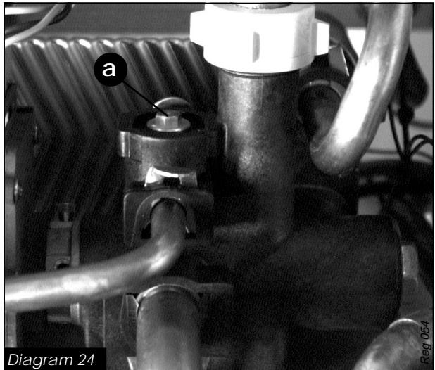
The ISOMAX has a built-in bypass. This must be adjusted according to the requirements of the system, refer to the flow rate pressure curve (diagram 4). The boiler is supplied with the built-in bypass open a half a turn. It is adjusted by turning the bypass screw (a), see diagram 24. Turn the screw clockwise to close the bypass. When using thermostatic radiator valves (TRV's) on all of the radiators, it is essential that a separate, adjustable bypass of 15 mm minimum diameter is fitted between the flow and return of the heating circuit, see diagram 8. Any bypass must be fitted before system controls.
MODULATING COIL
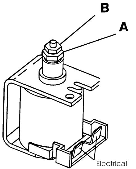
Diagram 23
Reg 020
natural_image
Close-up of a mechanical assembly with pipes and a central component, labeled 'a' and 'Diagram 24' (no readable text or symbols beyond labels)To ensure the continued efficient and safe operation of the boiler it is recommended that it is checked and serviced at regular intervals. The frequency of servicing will depend upon the particular installation conditions and usage, but in general once a year should be enough.
It is the law that any servicing is carried out by a qualified registered person.
Service Check and Preparation.
- Operate boiler and check for any faults that need to be put right.
- Isolate boiler from the gas and electrical supplies.
- On completion check all gas carrying parts for soundness with leak detection fluid.
- Remove boiler casing as follows:
Upper front panel
- Remove the two front panel retaining brackets from the top of the boiler.
- Remove panel by lifting up and forward.
Sealed chamber cover
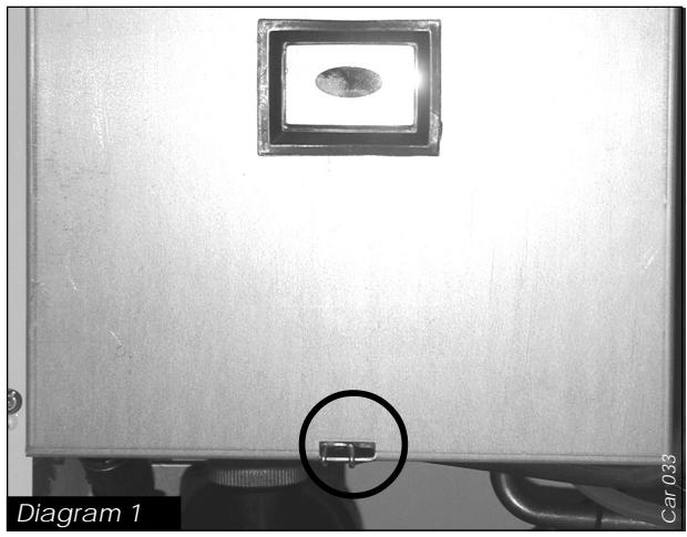
- Unclip the toggle clip holding the sealed chamber cover, see diagram. 1.
- Lift cover up and off boiler.
Front control panel
- Lift control panel up and lower forwards to gain access to lower part of boiler.
Side panels
- Unscrew and remove the four screws securing lower grille onto boiler. Unhook grille from rear of boiler and remove.
- Remove three screws from front of each side panel.
- Unclip the toggle clips securing top of each panel. Lift each panel up and then forward to remove.
Combustion chamber cover
- Unscrew the three screws securing combustion chamber cover to combustion chamber, see diagram 2.
- Remove combustion chamber cover from boiler.
- Undo, but do not remove, two burner support screws at rear of burner chamber.
Burner
- Undo main gas supply nut from burner.
- Pull off the ignition and flame sense leads from the gas valve remove burner from boiler by lifting up and pulling forwards from keyhole slots.
Note: The washer between main burner and main burner gas supply must be kept for use on reassembly. - Remove ignition and flame sense electrodes from burner.
- Unscrew and remove injector bar retaining screws and separate injector bar from burner.
- Examine and clean injectors as necessary.
Note: DO NOT use a wire or sharp instrument on the holes.
Clean burner by washing in soapy water. Dry thoroughly before re-fitting.
natural_image
Close-up of a metallic enclosure with a small circular inset showing a small object, labeled 'Diagram 1' and 'Car 033' (no readable text or symbols on the main subject)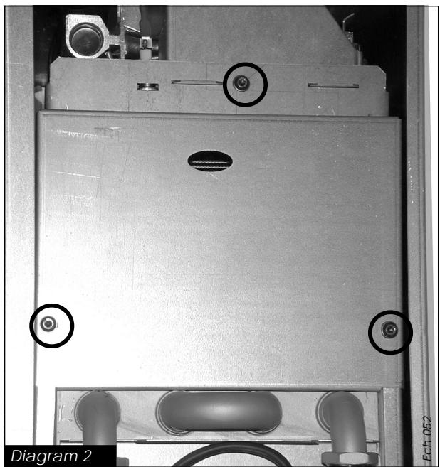
natural_image
Interior view of a mechanical device with labeled components and circular features (no readable text or symbols)Heat exchanger
- Disconnect power supply leads and earth lead from fan.
- Unscrew and remove, two fan retaining screws at front edge of fan mounting plate.
- Remove fan with mounting plate attached by pulling forwards out of boiler.
- Remove air pressure switch sensing tube from sensing probe on flue hood.
- Unscrew and remove screws securing flue hood to rear panel.
- Withdraw flue hood from boiler.
- Examine heat exchanger for any blockages or build up of deposits.
- Clean heat exchanger with soft brush or vacuum cleaner. Do not use any tool likely to damage painted finish of heat exchanger.
Reassembly of parts removed for servicing
All parts are replaced in reverse order to removal.
Flue system
- Check externally to make sure that flue is not blocked
- Inspect flue system to make sure that all fittings are secure.
Operation of fan
- Switch on electrical supply and turn on gas.
• Light burner by opening a hot water tap. - Without sealed chamber cover in place, burner should be automatically prevented from lighting by air flow detection system.
- Refit sealed chamber cover.
- Check that fan operates when burner lights and stops when it goes out.
Cold water inlet filter
Drain down hot water circuit of boiler only, as follows:
- Close isolating valve/throttle (m) on cold water isolating cock, see diagram 3.
Note: This valve is closed when screwed fully clockwise.
- Open one or more hot water taps to drain boiler circuit.
- Undo connecting nut from cold water inlet connection.
- Clean and inspect filter, replace if necessary.
- With both filter and restrictor in place, reconnect connecting pipe to inlet connection and tighten.
- Fully open isolating valve/throttle on cold water inlet and check for leaks.
REPLACEMENT OF PARTS
For replacement of the following components it will be necessary to remove boiler casing panels as described in 'Routine Cleaning and Inspection'.
WARNING: Before commencing the replacement of any component, isolate appliance from electrical supply and turn off gas at service cock.
To replace domestic hot water thermistor
- Locate domestic hot water thermistor on hot water flow pipe on right hand side of boiler adjacent to gas valve.
- Unclip thermistor from pipe.
- Disconnect leads from thermistor.
• Fit replacement thermistor. - Fit leads to replacement thermistor, the polarity is not important.
To replace central heating thermistor
- Locate central heating thermistor on heating flow pipe on centre of boiler.
- Unclip thermistor from pipe.
- Disconnect leads from thermistor.
• Fit replacement thermistor. - Fit leads to replacement thermistor, the polarity is not important.
To replace storage vessel thermistor
For this operation the boiler must be removed from the wall.
- Drain down heating and hot water circuit of the boiler only, as follows:
- Close isolating valves (q) and (v) on central heating isolating cocks (A) and (C), see diagram 3.
Note: These valves are closed when slots are at right angles to direction of flow.
- Drain boiler by opening drain valves (r) and (u), see diagram 3.
Note: It is not necessary to drain down entire heating system to carry out this work.
- Close isolating valve/throttle (m) on cold water isolating cock, see diagram 3.
Note: This valve is closed when screwed fully clockwise.
- Open one or more hot water taps to drain boiler circuit.
- Disconnect flue system.
- Disconnect boiler pipes onto fixing jig.
- Disconnect mains cable and any external controls cables.
- Remove boiler from wall.
- From rear of boiler, disconnect domestic pipes from storage vessel.
- Disconnect electrical connections from vessel.
- Unclip vessel from boiler frame and remove from boiler.
- Slide off plastic strap and separate two halves of vessel insulation.
- Locate thermistor at top of insulation.
- Replace thermistor in same position as old thermistor.
- Refit vessel in reverse order to removal.
- Refit boiler onto fixing jig, tighten all connections ensuring that all sealing washers are fitted before tightening.
- Reconnect flue making sure that all joints are properly connected.
- Open isolating valves on flow and return connections, refill, vent and pressurise boiler.
- Check for leaks.
- Reconnect all electrical connections and restore electrical supply.
- Open gas cock, operate boiler and re-check all joints for soundness.
To replace fan
- Remove fan as described in 'Routine Cleaning and Inspection'.
- Fit replacement fan in reverse order to removal.
- Reconnect electrical leads.
To replace air pressure switch
- Locate air pressure switch situated inside sealed chamber on top right hand side.
- Remove air pressure switch tube from sensing probe on flue hood.
- Disconnect air pressure switch electrical connections.
- Undo screws on top of boiler securing air pressure switch to boiler and remove switch.
- Pull sensing tube off switch.
- Fit replacement switch to boiler in reverse order to removal, noting that pressure sensing tube fits to left hand connection on switch.
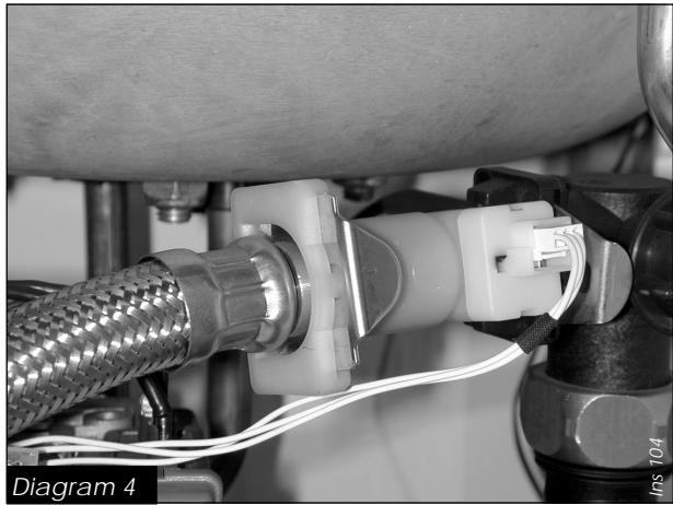
To replace domestic water flow sensor
- Drain down hot water circuit of boiler only as described previously.
- Undo connecting nut from cold water inlet connection.
- Locate flow sensor on cold water inlet pipe to boiler inside controls area, see diagram 4.
- Carefully pull off electrical connector from flow sensor.
- Pull out slotted metal clip securing cold water in-
let pipe to flow sensor and carefully remove from sensor.
- Pull out slotted metal clip securing flow sensor to pump mounting and carefully remove sensor from boiler.
- Fit replacement sensor to boiler in reverse order to removal.
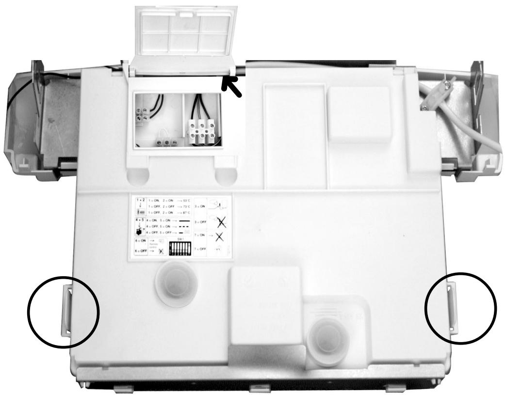
To replace printed circuit board (PCB)
- Gain access to rear of control panel.
- Unclip and remove external controls/mains connection access cover.
- Unclip side clips and hinge up control panel cover to gain access to PCB, see diagram 5.
- Carefully pull off electrical connections to PCB.
- Unclip and lift out PCB.
- Fit replacement PCB in reverse order to removal. Note: 1) Make sure that PCB connections are fully pushed onto replacement PCB.
2) Set the heating temperature option to the same value as the old PCB, refer to 'Installation and User' instructions.
natural_image
Close-up of a mechanical piping assembly with coiled white cables and a white connector (no text or symbols visible)Diagram 5
Acc 010/Acc011
To replace pump
- Drain down heating circuit of the boiler only, as described previously.
Note: It is not necessary to drain down entire heating system to carry out this work. - Undo two fixing screws and remove pump retaining bracket from front of pump.
- Undo clips securing pump outlet hose connection to pump.
- Slide hose along pipe to clear pump outlet.
- Disconnect pump electrical connection from PCB.
- Transfer automatic air vent to replacement pump using new washers supplied.
- Re-connect electrical connection to PCB.
- Fit replacement pump in reverse order to removal.
- Open isolating valves on flow and return connections, refill, vent and pressurise boiler.
- Check for leaks.
To replace domestic hot water heat exchanger
- Drain down heating and hot water circuits of boiler only as described previously.
Note: It is not necessary to drain down entire heating system to carry out this work. - Unscrew and remove cold water inlet pipe from fixing jig to water flow sensor.
- Supporting domestic heat exchanger, unscrew and remove two screws securing it onto pump mounting and 3-way valve/bypass housing.
- Remove heat exchanger from boiler.
- Fit replacement heat exchanger in reverse order to removal using new seals, supplied.
Note: Heat exchanger mounting screws are offset to ensure correct fitting of replacement.
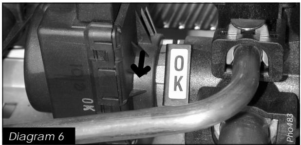
To replace 3-way valve head
- Locate 3-way valve in centre of lower controls area.
- Remove electrical plug from valve head.
- Pull out slotted metal clip from valve body and remove valve head from body.
- Fit replacement valve head in reverse order to removal.
Note :
1) When refiting clip, ensure that letters OK are as shown in diagram 6.
2) It is not necessary to drain boiler to carry out this work.
To replace 3-way valve/bypass housing
- Drain down heating and hot water circuit of boiler only as described previously.
Note: It is not necessary to drain down entire heating system to carry out this work. - Remove 3-way valve head as described previously.
- Remove domestic hot water heat exchanger as described previously.
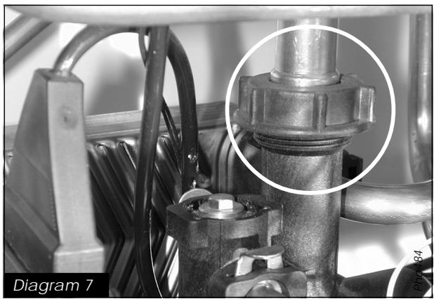
- Undo pipe connection from 3-way valve/bypass housing to primary heat exchanger, see diagram 7.
- Pull out slotted metal clips and remove bypass pipe.
• Pull out slotted metal clip and remove domestic
pipe from 3-way valve/bypass housing to storage vessel.
- Undo pipe from 3-way valve/bypass housing to fixing jig.
- From underneath boiler, undo two screws securing 3-way valve/bypass housing and lift out of boiler.
- Fit replacement 3-way valve/bypass housing in reverse order to removal.
To replace system pressure sensor
- Drain down heating circuit of boiler only as described previously.
Note: It is not necessary to drain down entire heating system to carry out this work.
- Locate system pressure sensor at front left hand side of boiler, see diagram 8.
- Remove electrical connections from sensor.
- Pull off slotted metal clip and remove sensor from boiler.
- Fit replacement sensor in reverse order to removal.
To replace gas valve module
- Locate gas valve module attached to side of gas valve.
natural_image
Close-up of mechanical components with a magnified inset showing a bolted joint detail (no text or symbols visible)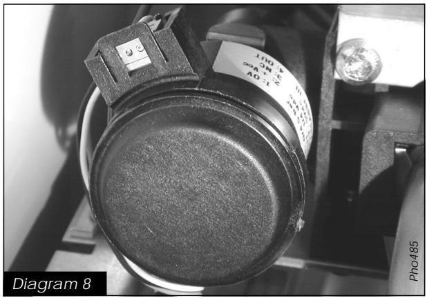
natural_image
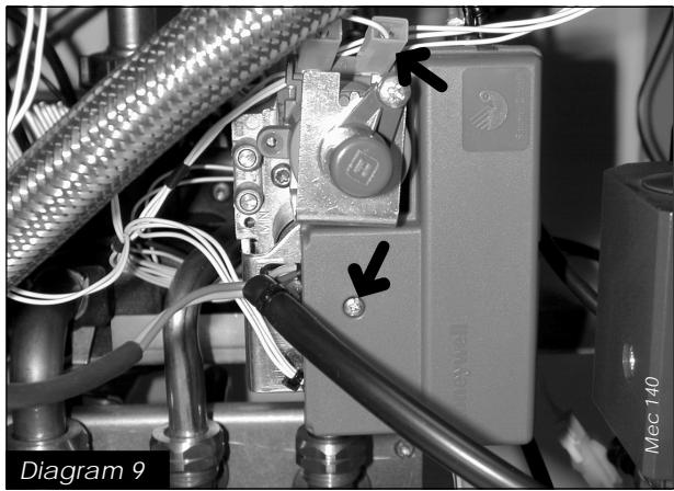
Close-up of a mechanical device with wires and connectors, labeled 'Diagram 9' (no readable text or symbols beyond labels)- Remove screw securing cover onto gas valve module, see diagram 9.
- Remove cover and disconnect multi-plug from module.
- Disconnect ignition and flame sense leads from module.
- Withdraw module from gas valve.
- Fit replacement module, ensuring it is of the correct type for the boiler, in reverse order to removal.
- Reconnect ignition and flame sense leads, the connections are uniquely sized to ensure correct replacement.
- Reconnect multi-plug onto replacement module.
- Refit cover ensuring all sealing grommets are correctly located in module body.
To replace gas valve
- Ensure that gas supply to boiler is turned off at gas cock.
- Remove gas valve module as described previously.
- Disconnect electrical connections to gas valve modulating coil, see diagram 9.
- Undo main gas supply nut from main burner.
Note: The washer must be kept for use on reassembly.
- Undo main gas union nut between gas valve supply pipe and gas inlet valve.
Note: The washer must be kept for use on reassembly.
- Disconnect plastic sensing pipe from gas valve to base of sealed chamber.
- Unscrew and remove screws securing gas valve bracket to boiler frame.
- Withdraw gas valve assembly.
- Using old gas valve as a guide, transfer gas pipes from old gas valve to replacement gas valve.
- Fit replacement gas valve into boiler.
- Reconnect gas pipes in reverse order to removal.
- Refit electrical connections in reverse order to removal, the polarity of the wires to the modulating coil is not important.
To replace modulating coil
- Ensure that gas supply to boiler is turned off at gas cock.
- Disconnect electrical connections to gas valve modulating coil, see diagram 9.
-
Undo two screws securing modulating coil to gas valve and remove coil.
-
Fit replacement coil in reverse order to removal.
- Refit electrical connections in reverse order to removal, the polarity of the wires to the modulating coil is not important.
To replace central heating safety valve
If safety valve seating is damaged, it will be necessary to replace safety valve as a complete unit, repair is not possible.
- Drain down heating circuit of boiler only as described previously.
- Disconnect safety valve discharge pipe from safety valve.
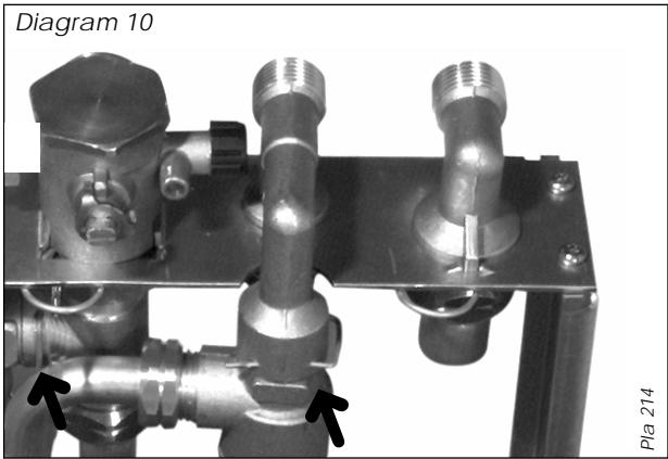
- Remove wire clip securing safety valve to fixing jig and remove safety valve, see diagram 10.
- Fit replacement safety valve in reverse order to removal.
Note: Apply a small quantity of silicon grease to the safety valve 'O' ring prior to fitting.
- Open isolating valves on flow and return connections, refill, vent and pressurise boiler.
- Check for leaks.
To replace storage vessel safety valve
If safety valve seating is damaged, it will be necessary to replace safety valve as a complete unit, repair is not possible.
- Drain down hot water circuit of boiler only as described previously.
- Disconnect safety valve discharge pipe from safety valve.
- Remove wire clip securing safety valve to fixing jig and remove safety valve, see diagram 10.
- Fit replacement safety valve in reverse order to removal.
Note: Apply a small quantity of silicon grease to the safety valve 'O' ring prior to fitting.
- Open isolating valve on cold water inlet connection.
- Check for leaks.
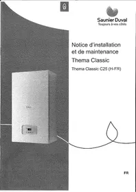
To replace heat exchanger
- Drain down heating circuit of boiler only as described previously.
Note: It is not necessary to drain down entire heating system to carry out this work. - Remove combustion chamber cover, as described in 'Routine Cleaning and Inspection'.
-
Disconnect electrical connector from high limit thermostat.
-
Remove slotted metal clips from heat exchanger connection pipes.
- Undo nut securing pipe from heat exchanger to 3-way valve/bypass housing.
- Swing pipe away from 3-way valve/bypass housing and pull down to disengage from heat exchanger pipe.
- Pull down pipe from pump to heat exchanger to disengage from heat exchanger pipe.
- Slide heat exchanger forwards and remove from boiler, see diagram 11.
- Fit replacement heat exchanger in reverse order to removal.
- Reconnect electrical connector to high limit thermostat.
- Open isolating valves on flow and return connections, refill, vent and pressurise boiler.
- Check for leaks.
natural_image
Industrial machine with heat exchanger and cooling pipes (no visible text or symbols)To replace central heating expansion vessel
Replacement of the expansion vessel is not possible with the boiler on the wall.
Remove boiler from wall as described in 'To replace storage vessel thermistor'.
- Undo pipe coupling on expansion vessel.
- Supporting expansion vessel, unscrew and remove screw securing expansion vessel to boiler.
- Lift vessel out of boiler.
- Fit replacement vessel to boiler in reverse order to removal, ensuring that sealing washer is fitted to pipe connection before tightening.
- Ensure that expansion vessel charge pressure is 0.5 bar (7.5 psi) using a pressure gauge. If necessary, increase pressure using a car or cycle tyre pump connected to the Schrader valve.
- Refit boiler onto fixing jig, tighten all connections ensuring that all sealing washers are fitted before tightening.
- Reconnect flue making sure that all joints are properly connected.
- Open isolating valves on flow and return connections, refill, vent and pressurise boiler.
- Check for leaks.
- Reconnect all electrical connections and restore electrical supply.
- Open gas cock, operate boiler and re-check all joints for soundness.
To replace high limit thermostat
- Locate high limit thermostat on heating flow pipe on left hand side of boiler.
- Disconnect electrical connection from thermostat
- Unclip thermostat from heating flow pipe.
- Fit replacement thermostat in reverse order to removal.
- Refit connection to thermostat.
To replace combustion chamber insulation
- Remove combustion chamber cover as described in 'Routine Cleaning and Inspection'.
- Remove heat exchanger as described previously.
- Remove fan and flue hood as described in 'Routine Cleaning and Inspection'.
Front panel:
- Lift front insulation panel free from retaining lugs on combustion chamber cover.
Rear panel:
- Pull rear insulation panel free from retaining lug at rear of combustion chamber by tilting forward.
- Fit replacement insulation panels in reverse order to removal
- Refit combustion chamber cover.
Side panels:
- Pull out side panels.
To replace burner
- Remove burner as described in 'Routine Cleaning and Inspection'.
Assemble replacement burner, supplied in parts, as follows: - Fit burner injectors to burner injector bar and tighten.
Note: Make sure that injector size, marked on each injector, is the same as that given in 'Technical Data' for the type of gas being used.
- Fit injector bar into burner, secure with retaining rods.
- Fit replacement burner into boiler in reverse order to removal.
To replace burner injectors
- Remove burner as described in 'Routine Cleaning and Inspection'.
- Pull out injector bar retaining rods and separate injector bar from burner.
- Unscrew and remove injectors from injector bar.
- Fit replacement injectors to injector bar and tighten.
Note: Make sure that injector size, marked on each injector, is the same as that given in 'Technical Data' for the type of gas being used.
- Reassemble burner and fit into boiler in reverse order to removal.
To replace ignition electrode
- Remove burner as described in 'Routine Cleaning and Inspection'.
- Undo and remove screw securing electrode onto burner.
- Fit replacement electrode onto burner in reverse order to removal.
- Refit burner into boiler in reverse order to removal.
To replace flame sense electrode
- Remove burner as described in 'Routine Cleaning and Inspection'.
- Undo and remove screw securing electrode onto burner.
- Fit replacement electrode onto burner in reverse order to removal.
- Refit burner into boiler in reverse order to removal.
1 - Domestic thermistor
2 - Three way valve
3 - Gas valve
4 - Gas valve ignition module
5 - Temperatur sensor for accumulation vessel
6 - Accumulation vessel
7 - Burner
8 - Ignition electrode
9 - Combustion chamber
10 - Heating safety valve (3 bar)
11 - Main heat exchanger
12 - Air pressure switch
13 - Flow detector
14 - DHW pump
15 - Non return valve
16 - Bypass
17 - Domestic heat exchanger
18 - Heating pump
19 - Heating expansion vessel
20 - Heating thermistor
21 - Overheat safety thermostat
22 - Flame sensor electrode
23 - Fan
24 - Domestic safety valve (6 bar)
25 - Loss of water sensor
26 - Domestic expansion vessel
27 - Pressure/temperature relief (7 bar)
28 - Domestic safety valve (10 bar)
A - Heating return
B - Cold water inlet
C - Heating flow
D - Domestic hot water outlet
E - Gas
D1 - Discharge from HTG safety valves
D2 - Discharge from DHW safety valves
D3 - Discharge from temp/press (to tundish)
flowchart
graph TD
    A["Component A"] --> B["Component B"]
    B --> C["Component C"]
    C --> D["Component D"]
    D --> E["Component E"]
    E --> F["Component F"]
    F --> G["Component G"]
    G --> H["Component H"]
    H --> I["Component I"]
    I --> J["Component J"]
    J --> K["Component K"]
    K --> L["Component L"]
    L --> M["Component M"]
    M --> N["Component N"]
    N --> O["Component O"]
    O --> P["Component P"]
    P --> Q["Component Q"]
    Q --> R["Component R"]
    R --> S["Component S"]
    S --> T["Component T"]
    T --> U["Component U"]
    U --> V["Component V"]
    V --> W["Component W"]
    W --> X["Component X"]
    X --> Y["Component Y"]
    Y --> Z["Component Z"]
    Z --> AA["Component AA"]
    AA --> AB["Component AB"]
    AB --> AC["Component AC"]
    AC --> AD["Component AD"]
    AD --> AE["Component AE"]
    AE --> AF["Component AF"]
    AF --> AG["Component AG"]
    AG --> AH["Component AH"]
    AH --> AI["Component AI"]
    AI --> AJ["Component AJ"]
    AJ --> AK["Component AK"]
    AK --> AL["Component AL"]
    AL --> AM["Component AM"]
    AM --> AN["Component AN"]
    AN --> AO["Component AO"]
Diagram 12
Heating
| Heating output | ajustable from 10,1 kW to 27,6 kW from 35,484 BTU/H to 94,170 BTU/H |
| Efficiency | 91 % |
| Maximum heating temperature | 87 °C |
| Expansion vessel effective capacity | 8 l |
| Expansion vessel charge pressure | 0,5 bar |
| Maximum system capacity at 75°C | 180 l |
| Safety valve, maximum service pressure | 3 bar |
| Products outlet diameter | 60 mm |
| Fresh air inlet diameter | 100 mm |
Hot water
| Hot water output, automatically variable from 10,4 kW to 27,6 kW from 35,484 BTU/H to 94,170 BTU/H | |
| Maximum hot water temperature | 60 °C |
| Specific flow rate (for 30°C temp rise) | 13,2 l/min. |
| Threshold flow rate | 1 l/min. |
| Nominal water flow rate | 11,3 l/min. |
| Maximum supply pressure | 8 bar |
| Minimum operating pressure | 0,7 bar |
| Electrical supply | 230 V |
| Maximum absorbed power | 235 W |
| Level of protection | IP44 |
Natural Gas (G20)
| Burner injector | 1,20 mm |
| Inlet pressure | 20 mbar |
| Maxi. Burner pressure | 13,8 mbar |
| Mini. Burner pressure | 2,16 mbar |
| Gas rate maximum | 3,20 m^3/h |
| Gas rate minimum | 1,32 m^3/h |
Butane Gas (G30)
| ∅ Burner injector | 0,77 mm |
| Inlet pressure | 29 mbar |
| Maxi. Burner pressure | 23,8 mbar |
| Mini. Burner pressure | 3,6 mbar |
| Gas rate maximum | 2,39 kg/h |
| Gas rate minimum | 0,99 kg/h |
Propane Gas (G31)
| ∅ Burner injector | 0,77 mm |
| Inlet pressure | 37 mbar |
| Maxi. Burner pressure | 30,8 mbar |
| Mini. Burner pressure | 3,6 mbar |
| Gas rate maximum | 2,35 kg/h |
| Gas rate minimum | 0,97 kg/h |
1 Bypass fully shut
② Open 1/4 turn
3 Open 1/2 turn
4 Open 1 turn
5 Open 2 turns
line
| Flow rate through heating system (l/h) | Available pressure (kPa) between heating supply and return lines (l=10 kPa = 1 m WG) | | ---------------------------------------- | ---------------------------------------------------------------------------------- | | 200 | 50 | | 400 | 35 | | 600 | 30 | | 800 | 25 | | 1000 | 20 | | 1200 | 18 |1 Bypass fully shut
② Open 1/4 turn
3 Open 1/2 turn
4 Open 1 turn
5 Open 2 turns
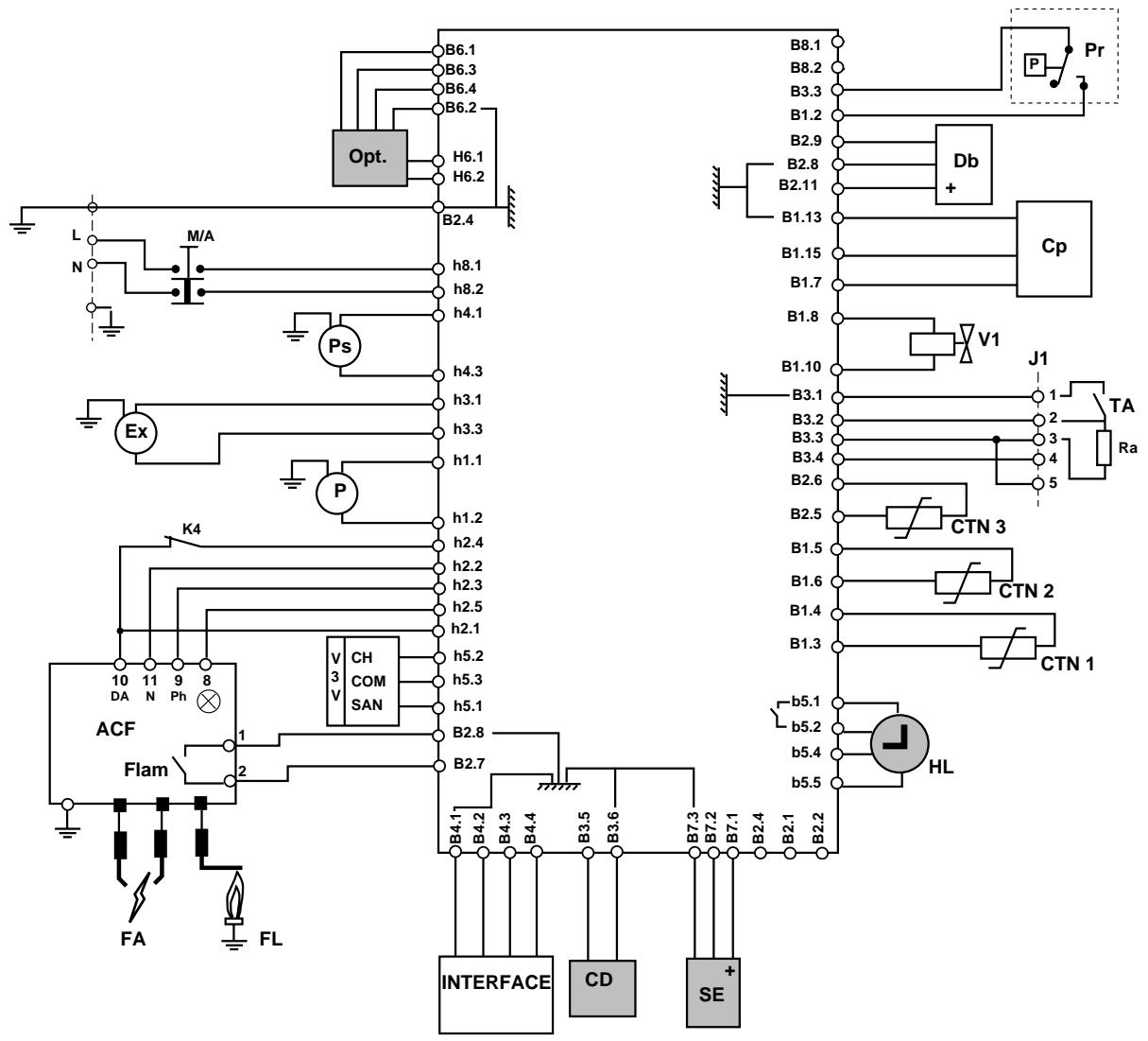
M/A - on/ off
Ps - domestic water pump
P - heating pump
ACF - ignition card and flame control
DA - ignition demand
⊗ - safety engaged
Flam - ionisation contact
V3V - three-way valve
CH - heating
COM - common
SAN - hot water
INTERFACE - User interface
Db - output detector
Cp - water pressure sensor
V1 - gas mechanism modulating valve
J1 - connector for room temp. thermostat
TA - room temperature thermostat
Ra - room temp. thermostat anticipation resistor
FA - ignition electrodes
FL - ionisation electrode
CTN1 - hot water thermistor
CTN2 - heating thermistor
CTN3 - accumulator thermistor
K4 - overheating safety
Pr - air pressure switch
Ex - fan
accessories
Opt - option card
CD - remote control
SE - external sensor
HL - clock
Before trying to operate the boiler make sure that :
- All gas supply cocks are open and that the gas supply has been purged of air.
- The heating system pressure is at least 1 bar.
- There is a permanent mains supply to the boiler.
- The fuse on the PCB is intact.
WARNING. Always isolate the boiler from the electrical supply before carrying out any electrical replacement work.
Always check for gas soundness after any service work.
Should there be any doubt about the voltage supply to any of the components, it is possible to carry out a simple electrical test to ensure all is operational in that area.
To carry out the electrical test, gain access to the main Printed Circuit Board (PCB), as described previously, and measure the voltages according to table 1.
Table 1
| Voltage | Measured value | Measuring point |
| 230 Volt | 230 V AC | Between terminals H8.1 and H8.2 |
| 24 Volt | maximum 33V DC minimum 20V DC | Between terminals B2.4 and B2.7 |
| 15 Volt | 15V ± 0.5V | Between terminals B2.4 and B2.2 |
| Display | 5V ± 0.5V | Between terminals B2.4 and B4.2 |
The ISOFAST has an on-board fault diagnostic system. Should a fault occur on the boiler, the warning LED at the top of the user display ⚠️ will illuminate and the LCD display will indicate the precise area where the fault has occurred.
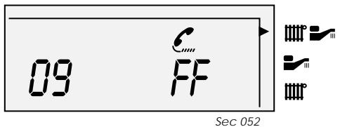
A fault code is displayed on the left hand side of the LCD display, whilst at the same time, the letters FF appear with a telephone symbol.
List of fault codes
| Code | Fault | Additional display information |
| 00 | No fault | [TTTRX] |
| 02 | Air flow fault |  FF FF |
| 04 | Ignition fault -flame detection | [PTN2] |
| 05 | Overheating | [PTN2] FF |
| 06 | Central heating thermistor/wiring fault | [PTN2] FF |
| 07 | Domestic hot water thermistor/wiring fault | [PTN2] FF |
| 08 | Storage vessel thermistor/wiring fault | [PTN2] FF |
| 09 | System pressure sensor fault | [PTN2] FF |
| 10 | Fan fault | [PTN2] FF |
| 11 | Pump blockage | [PTN2] FF |
| 12 | User interface fault | [PTN2] FF |
| 13 | Main PCB fault | [PTN2] FF |
| 14 | CTN2 > 97°C - pump will run | [PTN2] FF |
| 15 | Gas mechanism fault | [PTN2] FF |
| 20 | Communication fault | [PTN2] FF |
Thermistor values
The following table applies to the central heating, domestic hot water and storage vessel thermistors:
| Temperature (°C) | Resistance (Ω) |
| 0 | 32565 |
| 5 | 25345 |
| 10 | 19875 |
| 15 | 15700 |
| 20 | 12500 |
| 25 | 10000 |
| 30 | 8060 |
| 35 | 6535 |
| 40 | 5330 |
| 45 | 4370 |
| 50 | 3605 |
| 55 | 2989 |
| 60 | 2490 |
| 65 | 2085 |
| 70 | 1755 |
| 75 | 1480 |
| 80 | 1260 |
| 85 | 1070 |
| 90 | 920 |
| 95 | 785 |
| 100 | 680 |
System pressure sensor
The resistance of the sensor at various pressures is as follows :
0 bar ...... between 280 Ω and 320 Ω
1 bar ...... between 195 Ω and 220 Ω
3 bar ...... between 93 Ω and 143 Ω
SPARE PARTS
When ordering spare parts, quote the part number and description, stating the appliance model number and serial number from the data badge.
Short parts list
No. .....Description .... Part No.
1 ...... Domestic hot water thermistor ...... 57213
2 .... Central heating thermistor .... 57215
3 ...... Storage vessel thermistor ...... 57250
4 ...... Fan ...... 57238
5 ...... Air pressure switch ...... 57237
6 ...... Domestic water flow sensor ...... 57202
7 ...... Printed circuit board ...... 57248
8 ...... Pump ...... 57207
9 3-way valve head 57206
10 ...... System pressure sensor ...... 57205
11 ...... Gas valve module ...... 57079
12 ...... Central heating safety valve ...... 57228
13 ...... Storage vessel safety valve ...... 57229
14 ...... High limit thermostat ...... 57212
15 ..... Ignition electrode ..... 57194
16 ..... Flame sense electrode ..... 57195